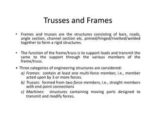
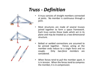
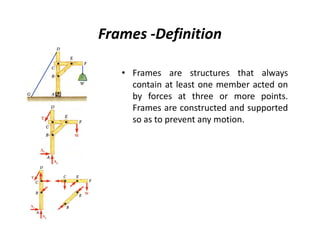
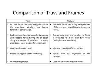
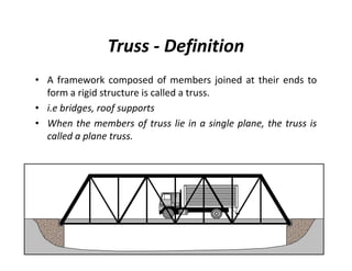
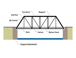
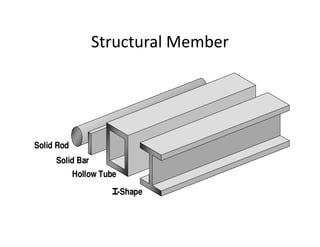
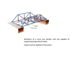
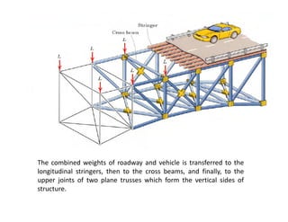
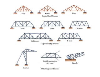
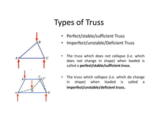
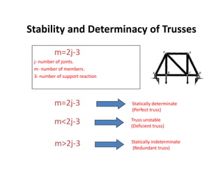
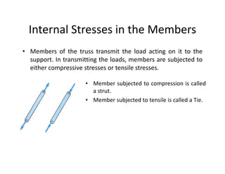
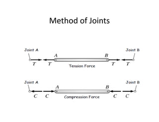
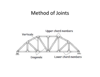
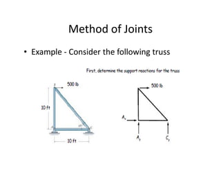
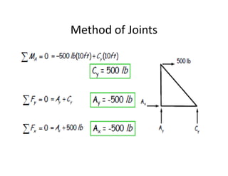
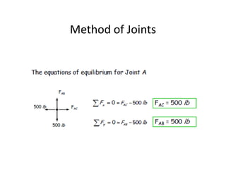
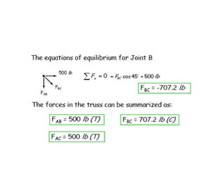
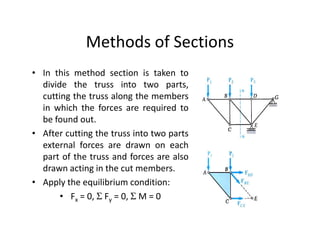
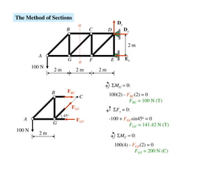
Trusses and Frames
• Frames and trusses are the structures consisting of bars, roads,
  angle section, channel section etc. pinned/hinged/rivetted/welded
  together to form a rigid structures.

• The function of the frame/truss is to support loads and transmit the
  same to the support through the various members of the
  frame/truss.
• Three categories of engineering structures are considered:
   a) Frames: contain at least one multi-force member, i.e., member
      acted upon by 3 or more forces.
   b) Trusses: formed from two-force members, i.e., straight members
      with end point connections
   c) Machines: structures containing moving parts designed to
      transmit and modify forces.
Truss - Definition
   • A truss consists of straight members connected
     at joints. No member is continuous through a
     joint.

   • Most structures are made of several trusses
     joined together to form a space framework.
     Each truss carries those loads which act in its
     plane and may be treated as a two-dimensional
     structure.

   • Bolted or welded connections are assumed to
     be pinned together. Forces acting at the
     member ends reduce to a single force and no
     couple.     Only two-force members are
     considered.

   • When forces tend to pull the member apart, it
     is in tension. When the forces tend to compress
     the member, it is in compression.
Frames -Definition

   • Frames are structures that always
     contain at least one member acted on
     by forces at three or more points.
     Frames are constructed and supported
     so as to prevent any motion.
Comparison of Truss and Frames
                    Truss                                      Frames
• In truss forces act only along the axis of • In frames forces are acting along the axis
  the members. Members are having              of the member. In addition to transverse
  tension or compression.                      forces.

• Each member is acted upon by two equal • One or more than one member of frame
  and opposite forces having line of action is subjected to more than two forces
  along the centre of members. i.e. every   (multiple force members).
  member of truss is a two force member.

• Member does not bend.                      • Members may bend/may not bend.

• Forces are applied at the joints only.     • Forces may act anywhere          on the
                                               member.

• Used for large loads.                      • Used for small and medium loads.
Types of Truss Connections

 Pinned             Gusset Plate
 Connection         Connection
Truss - Definition
• A framework composed of members joined at their ends to
  form a rigid structure is called a truss.
• i.e bridges, roof supports
• When the members of truss lie in a single plane, the truss is
  called a plane truss.
Structural Member


Solid Rod
     Solid Bar
            Hollow Tube
                          -Shape
Members of a truss are slender and not capable of
supporting large lateral loads.
Loads must be applied at the joints.
The combined weights of roadway and vehicle is transferred to the
longitudinal stringers, then to the cross beams, and finally, to the
upper joints of two plane trusses which form the vertical sides of
structure.
Uses of truss
•   Roof of factory shade.
•   Ware house
•   Railway platform
•   Garage shed
•   Transmission towers
•   Crane truss
•   Bridge Truss
•   Sport Stadium Truss
Types of Truss
  • Perfect/stable/sufficient Truss
  • Imperfect/unstable/Deficient Truss

  • The truss which does not collapse (i.e. which
    does not change in shape) when loaded is
    called a perfect/stable/sufficient truss.

  • The truss which collapse (i.e. which do change
    in shape) when loaded is called a
    imperfect/unstable/deficient truss.
Stability and Determinacy of Trusses
          m=2j-3
 j- number of joints.
 m- number of members.
 3- number of support reaction


          m=2j-3                 Statically determinate
                                 (Perfect truss)

          m<2j-3                 Truss unstable
                                 (Deficient truss)


          m>2j-3                 Statically indeterminate
                                 (Redundant truss)
Loads on Truss
• Weight of the roof
• Wind load acting on the roof
• Travelling loads of cars, trucks, trains etc. On the bridge
  structure
• Weight of the structure it self. ( Generally Neglected)
• Reactions at the supports.
Internal Stresses in the Members
• Members of the truss transmit the load acting on it to the
  support. In transmitting the loads, members are subjected to
  either compressive stresses or tensile stresses.

                     • Member subjected to compression is called
                       a strut.
                     • Member subjected to tensile is called a Tie.
Assumptions for Analysis of Truss
• Truss joints are frictionless pin joints. They cannot resist
  moments.
• Load are applied only at the joints.
• Truss members are straight and uniform in section.
• Each member of the truss is subjected to axial force only.
• The truss is assumed perfect.(i.e. m= 2j-3)
• Members of truss has negligible weight as compare to the
  loads applied.
• Each member of the truss is two force member.
• The truss is rigid and does not change in shape.
Methods of analysis of Truss
1. Method of joints
2. Method of sections
Method of Joints
• If a truss is in equilibrium, then each of its joints must be in
  equilibrium.
• The method of joints consists of satisfying the equilibrium
  equations for forces acting on each joint.
                     Σ Fx = 0, Σ Fy = 0, Σ M = 0

• Methods of joint is most suited when forces in all the
  members are required to be obtained.
Method of Joints
• Steps
• Decide whether a truss is perfect or not, using equation; m = 2j-3.
• Find support reactions for simply supported truss, using three conditions
  of equilibrium.
   – Considering entire truss as a single unit.
• Force acting at all the joints are coplanar concurrent and assumed to be in
  static equilibrium and hence
   – (i) apply (a) Σ H= 0 and (b) Σ V= 0 for the purpose of analysis.
   – Or (ii) since the forces acting at the joints are in equilibrium, plot all
      the forces in magnitude and direction to get either a closed force
      triangle or closed force polygon .
• Each members of the truss is assumed to be in equilibrium hence apply
  equal, opposite and collinear forces at the two ends along the centre line
  of the member.
• Start the analysis only with a joint where there are only two unknowns.
  Do not start the analysis with a joint where unknowns are more than two.
    – Since, Σ H= 0 and (b) Σ V= 0 provide only two equations to solve the
      unknowns.
Method of Joints
     • Dismember the truss and create a
       free body diagram for each
       member and pin.

     • The two forces exerted on each
       member are equal, have the
       same line of action, and opposite
       sense.

     • Forces exerted by a member on
       the pins or joints at its ends are
       directed along the member and
       equal and opposite.
Method of Joints
Method of Joints
Method of Joints
• Example - Consider the following truss
Method of Joints
Method of Joints
Methods of Sections
• The method of joints is most effective when the forces in all
  the members of a truss are to be determined.
• If however, the force is only one or a few members are
  needed, then the method of sections is more efficient.
Methods of Sections
• In this method section is taken to
  divide the truss into two parts,
  cutting the truss along the members
  in which the forces are required to
  be found out.
• After cutting the truss into two parts
  external forces are drawn on each
  part of the truss and forces are also
  drawn acting in the cut members.
• Apply the equilibrium condition:
       • Fx = 0, Σ Fy = 0, Σ M = 0
Methods of Sections
• Cutting a truss care should be taken, not to cut more than
  three members of the truss at one time in which the forces
  are not known.
The Method of Sections
                             a                   Dy
                      B            C        D         Dx


                                                       2m

           A
                       G           F        E         Ex
                             a
        100 N
                2m           2m        2m


                                        + ΣMG = 0:
                B      FBC
                              C             100(2) - FBC(2) = 0
                                                      FBC = 100 N (T)
                           FGC
                                        + ΣFy = 0:
                     45o
   A                         FGF            -100 + FGCsin45o = 0
                G                                    FGC = 141.42 N (T)
100 N
           2m
                                            + ΣMC = 0:
                                                100(4) - FGF(2) = 0
                                                          FGF = 200 N (C)
Any Question?
Thank you

Chapter 3

  • 2.
    Trusses and Frames •Frames and trusses are the structures consisting of bars, roads, angle section, channel section etc. pinned/hinged/rivetted/welded together to form a rigid structures. • The function of the frame/truss is to support loads and transmit the same to the support through the various members of the frame/truss. • Three categories of engineering structures are considered: a) Frames: contain at least one multi-force member, i.e., member acted upon by 3 or more forces. b) Trusses: formed from two-force members, i.e., straight members with end point connections c) Machines: structures containing moving parts designed to transmit and modify forces.
  • 3.
    Truss - Definition • A truss consists of straight members connected at joints. No member is continuous through a joint. • Most structures are made of several trusses joined together to form a space framework. Each truss carries those loads which act in its plane and may be treated as a two-dimensional structure. • Bolted or welded connections are assumed to be pinned together. Forces acting at the member ends reduce to a single force and no couple. Only two-force members are considered. • When forces tend to pull the member apart, it is in tension. When the forces tend to compress the member, it is in compression.
  • 4.
    Frames -Definition • Frames are structures that always contain at least one member acted on by forces at three or more points. Frames are constructed and supported so as to prevent any motion.
  • 5.
    Comparison of Trussand Frames Truss Frames • In truss forces act only along the axis of • In frames forces are acting along the axis the members. Members are having of the member. In addition to transverse tension or compression. forces. • Each member is acted upon by two equal • One or more than one member of frame and opposite forces having line of action is subjected to more than two forces along the centre of members. i.e. every (multiple force members). member of truss is a two force member. • Member does not bend. • Members may bend/may not bend. • Forces are applied at the joints only. • Forces may act anywhere on the member. • Used for large loads. • Used for small and medium loads.
  • 6.
    Types of TrussConnections Pinned Gusset Plate Connection Connection
  • 7.
    Truss - Definition •A framework composed of members joined at their ends to form a rigid structure is called a truss. • i.e bridges, roof supports • When the members of truss lie in a single plane, the truss is called a plane truss.
  • 9.
    Structural Member Solid Rod Solid Bar Hollow Tube -Shape
  • 10.
    Members of atruss are slender and not capable of supporting large lateral loads. Loads must be applied at the joints.
  • 11.
    The combined weightsof roadway and vehicle is transferred to the longitudinal stringers, then to the cross beams, and finally, to the upper joints of two plane trusses which form the vertical sides of structure.
  • 13.
    Uses of truss • Roof of factory shade. • Ware house • Railway platform • Garage shed • Transmission towers • Crane truss • Bridge Truss • Sport Stadium Truss
  • 20.
    Types of Truss • Perfect/stable/sufficient Truss • Imperfect/unstable/Deficient Truss • The truss which does not collapse (i.e. which does not change in shape) when loaded is called a perfect/stable/sufficient truss. • The truss which collapse (i.e. which do change in shape) when loaded is called a imperfect/unstable/deficient truss.
  • 21.
    Stability and Determinacyof Trusses m=2j-3 j- number of joints. m- number of members. 3- number of support reaction m=2j-3 Statically determinate (Perfect truss) m<2j-3 Truss unstable (Deficient truss) m>2j-3 Statically indeterminate (Redundant truss)
  • 22.
    Loads on Truss •Weight of the roof • Wind load acting on the roof • Travelling loads of cars, trucks, trains etc. On the bridge structure • Weight of the structure it self. ( Generally Neglected) • Reactions at the supports.
  • 23.
    Internal Stresses inthe Members • Members of the truss transmit the load acting on it to the support. In transmitting the loads, members are subjected to either compressive stresses or tensile stresses. • Member subjected to compression is called a strut. • Member subjected to tensile is called a Tie.
  • 24.
    Assumptions for Analysisof Truss • Truss joints are frictionless pin joints. They cannot resist moments. • Load are applied only at the joints. • Truss members are straight and uniform in section. • Each member of the truss is subjected to axial force only. • The truss is assumed perfect.(i.e. m= 2j-3) • Members of truss has negligible weight as compare to the loads applied. • Each member of the truss is two force member. • The truss is rigid and does not change in shape.
  • 25.
    Methods of analysisof Truss 1. Method of joints 2. Method of sections
  • 26.
    Method of Joints •If a truss is in equilibrium, then each of its joints must be in equilibrium. • The method of joints consists of satisfying the equilibrium equations for forces acting on each joint. Σ Fx = 0, Σ Fy = 0, Σ M = 0 • Methods of joint is most suited when forces in all the members are required to be obtained.
  • 27.
    Method of Joints •Steps • Decide whether a truss is perfect or not, using equation; m = 2j-3. • Find support reactions for simply supported truss, using three conditions of equilibrium. – Considering entire truss as a single unit. • Force acting at all the joints are coplanar concurrent and assumed to be in static equilibrium and hence – (i) apply (a) Σ H= 0 and (b) Σ V= 0 for the purpose of analysis. – Or (ii) since the forces acting at the joints are in equilibrium, plot all the forces in magnitude and direction to get either a closed force triangle or closed force polygon . • Each members of the truss is assumed to be in equilibrium hence apply equal, opposite and collinear forces at the two ends along the centre line of the member. • Start the analysis only with a joint where there are only two unknowns. Do not start the analysis with a joint where unknowns are more than two. – Since, Σ H= 0 and (b) Σ V= 0 provide only two equations to solve the unknowns.
  • 28.
    Method of Joints • Dismember the truss and create a free body diagram for each member and pin. • The two forces exerted on each member are equal, have the same line of action, and opposite sense. • Forces exerted by a member on the pins or joints at its ends are directed along the member and equal and opposite.
  • 29.
  • 30.
  • 31.
    Method of Joints •Example - Consider the following truss
  • 32.
  • 33.
  • 35.
    Methods of Sections •The method of joints is most effective when the forces in all the members of a truss are to be determined. • If however, the force is only one or a few members are needed, then the method of sections is more efficient.
  • 36.
    Methods of Sections •In this method section is taken to divide the truss into two parts, cutting the truss along the members in which the forces are required to be found out. • After cutting the truss into two parts external forces are drawn on each part of the truss and forces are also drawn acting in the cut members. • Apply the equilibrium condition: • Fx = 0, Σ Fy = 0, Σ M = 0
  • 37.
    Methods of Sections •Cutting a truss care should be taken, not to cut more than three members of the truss at one time in which the forces are not known.
  • 38.
    The Method ofSections a Dy B C D Dx 2m A G F E Ex a 100 N 2m 2m 2m + ΣMG = 0: B FBC C 100(2) - FBC(2) = 0 FBC = 100 N (T) FGC + ΣFy = 0: 45o A FGF -100 + FGCsin45o = 0 G FGC = 141.42 N (T) 100 N 2m + ΣMC = 0: 100(4) - FGF(2) = 0 FGF = 200 N (C)
  • 39.
  • 40.