Downloaded 1,626 times
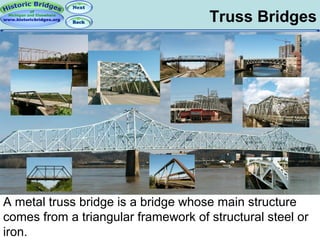


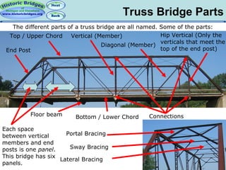
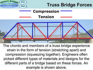
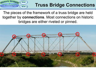


This document provides information about metal truss bridges, including their basic components and configurations. It explains that trusses can be classified as pony, through, or deck bridges depending on their design. Common truss types include Pratt, Whipple, Warren, Baltimore, and Pennsylvania configurations, which vary in their arrangement of diagonal and vertical members. Historic truss bridges used either pinned or riveted connections. The document encourages educating others about the importance of preserving historic bridges.


