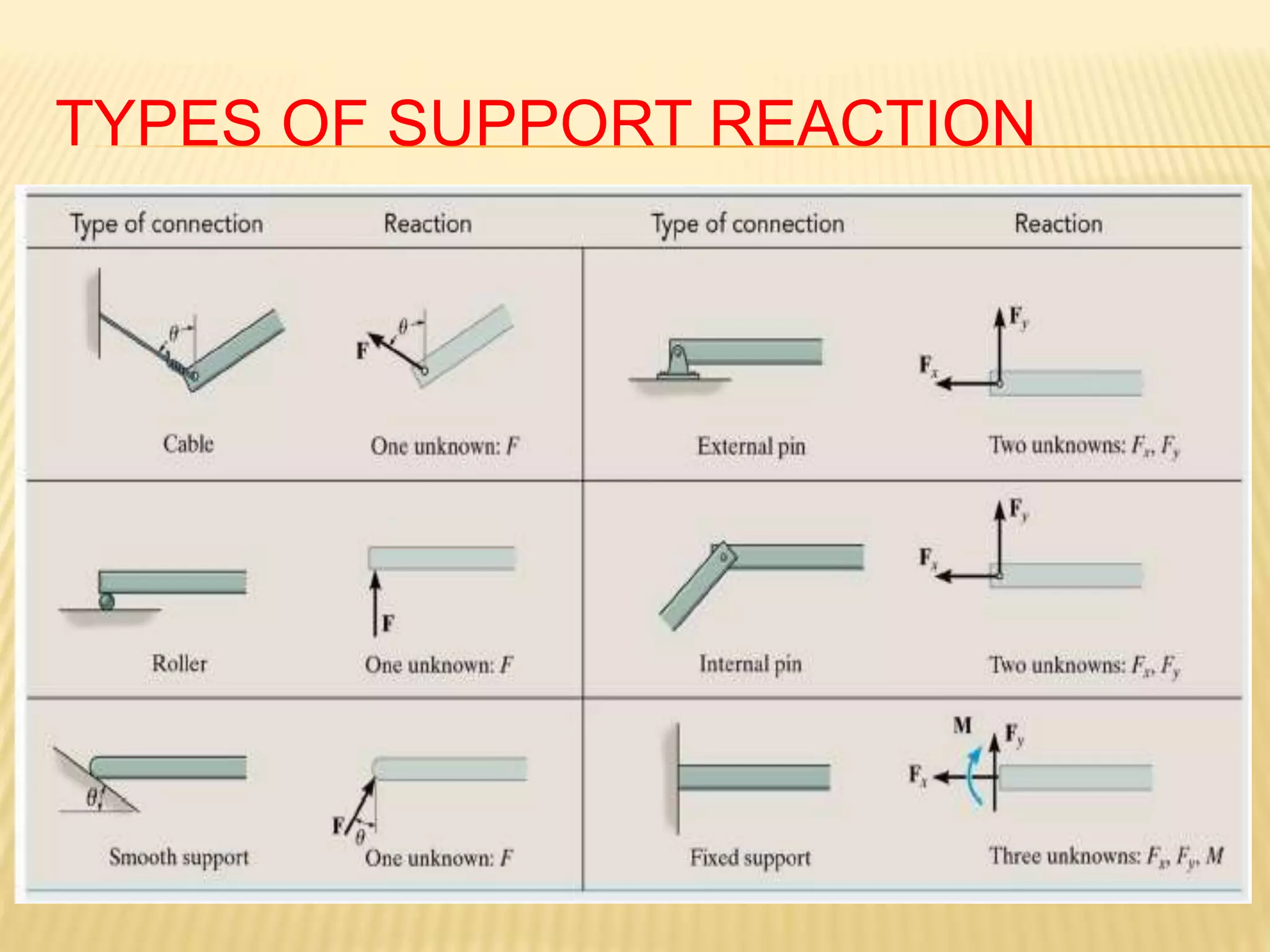
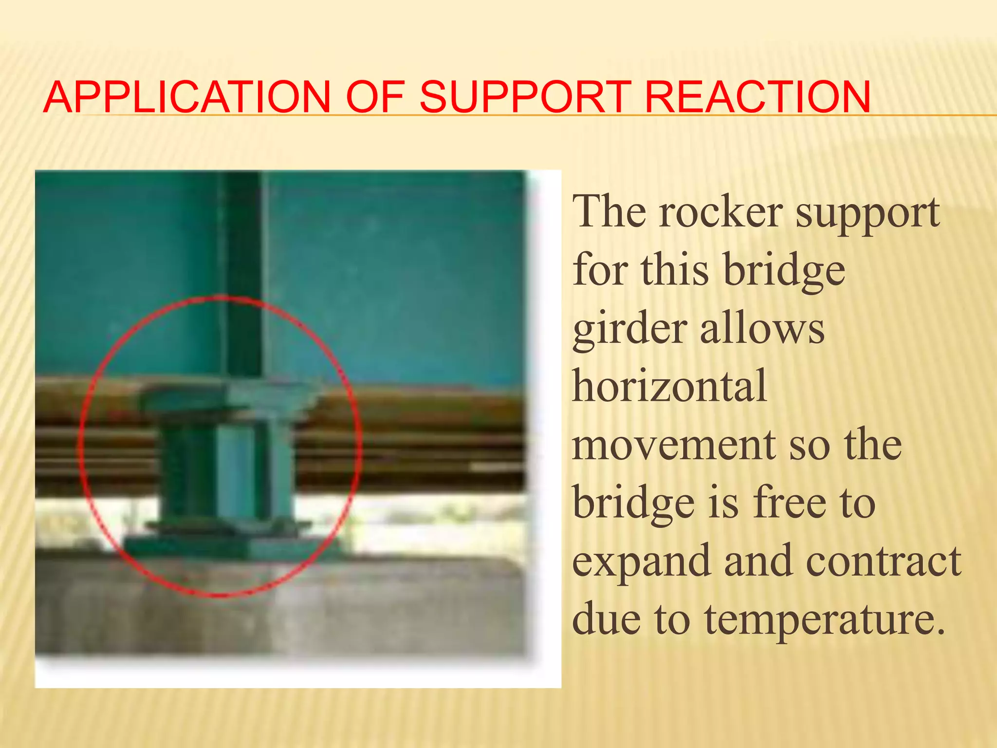
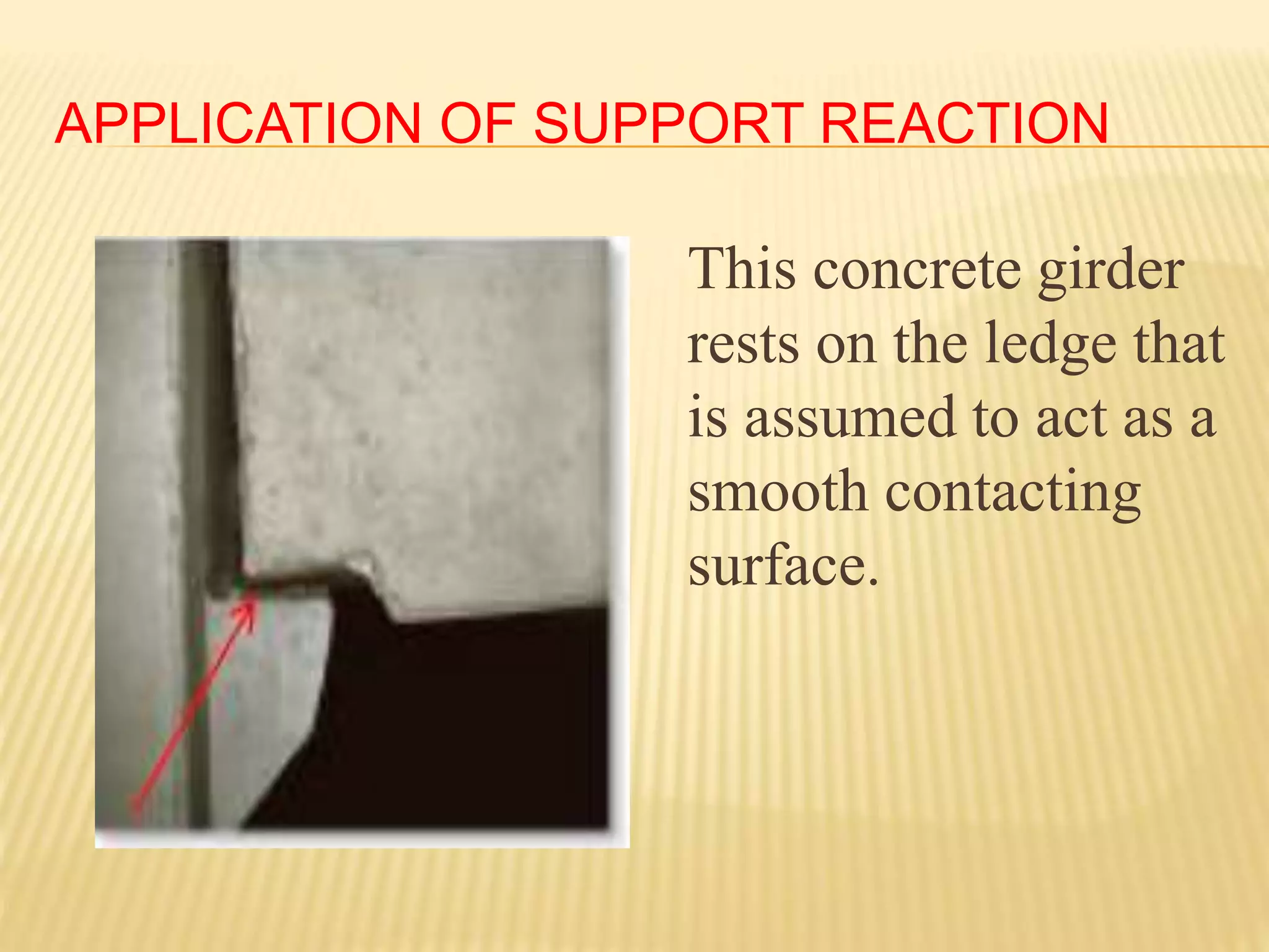
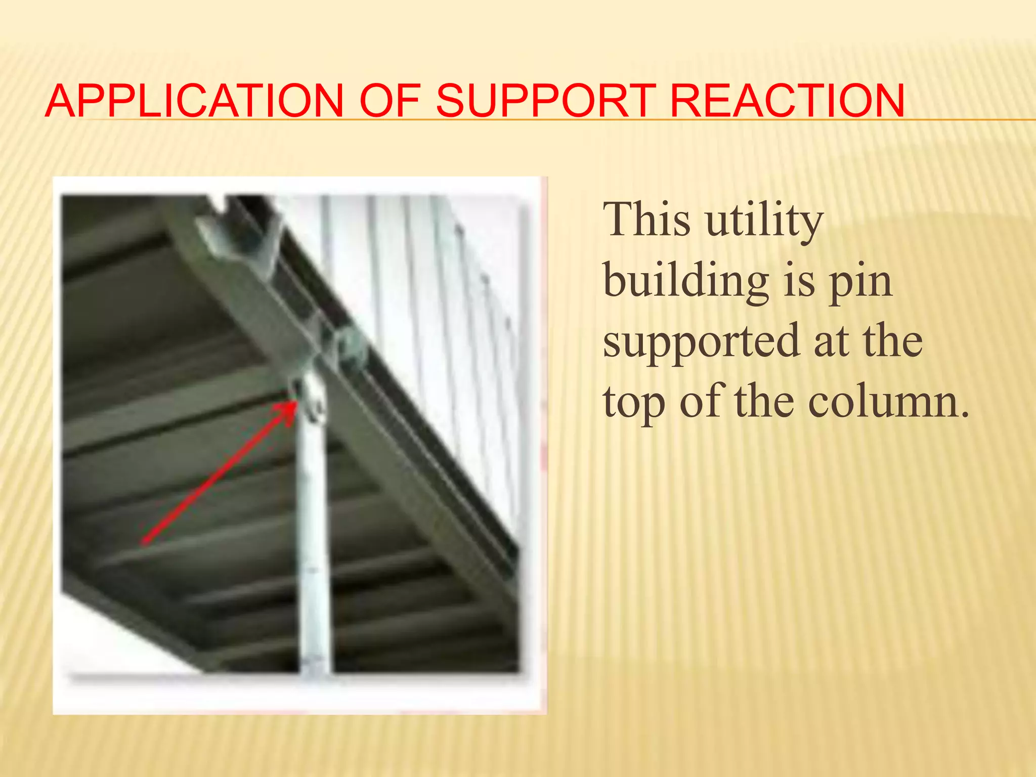
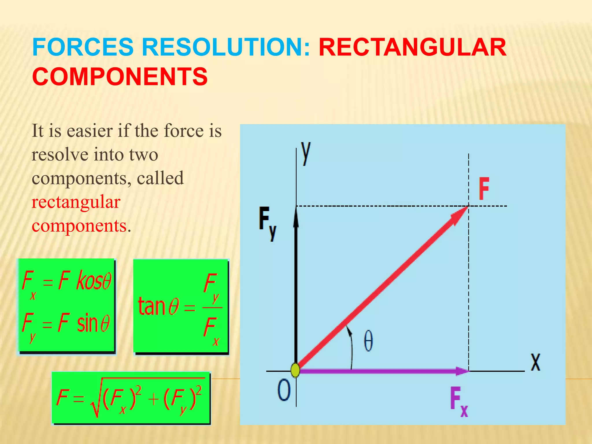
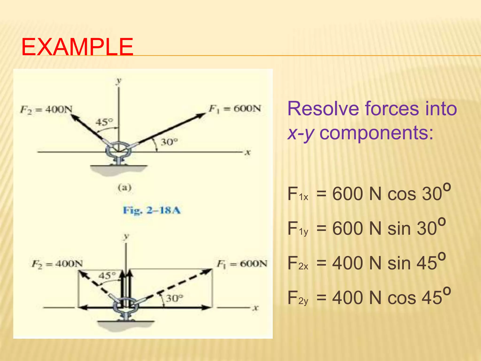
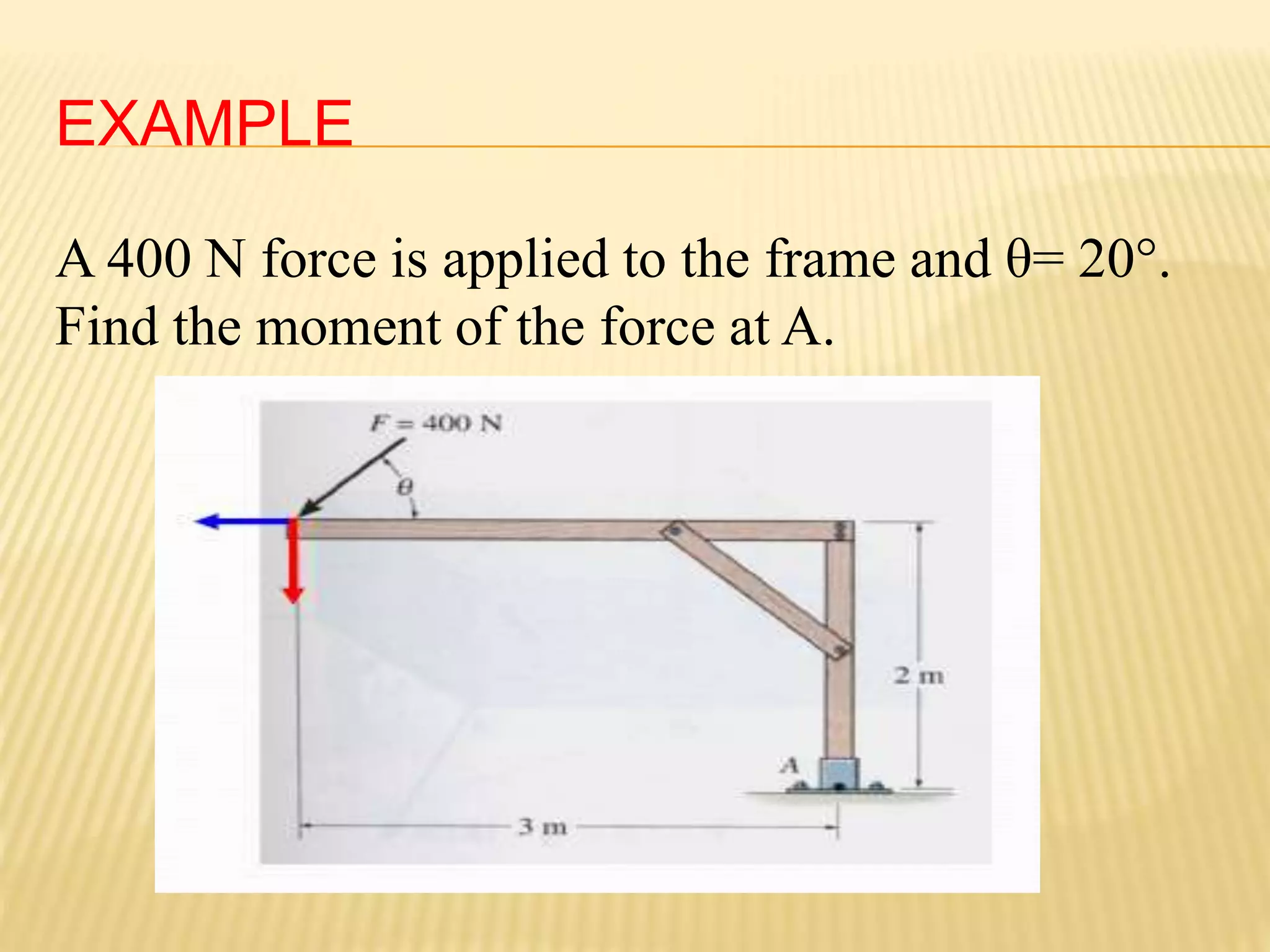
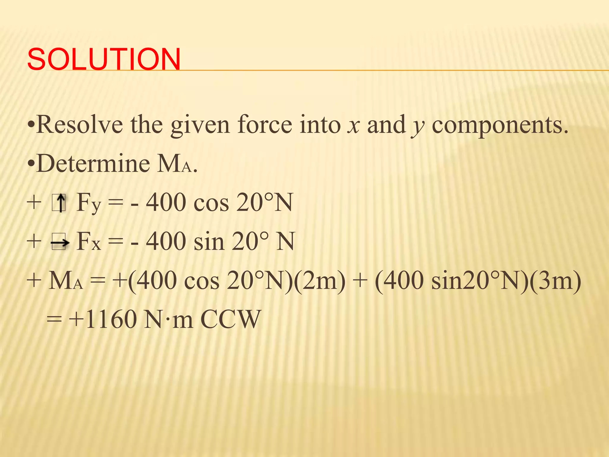
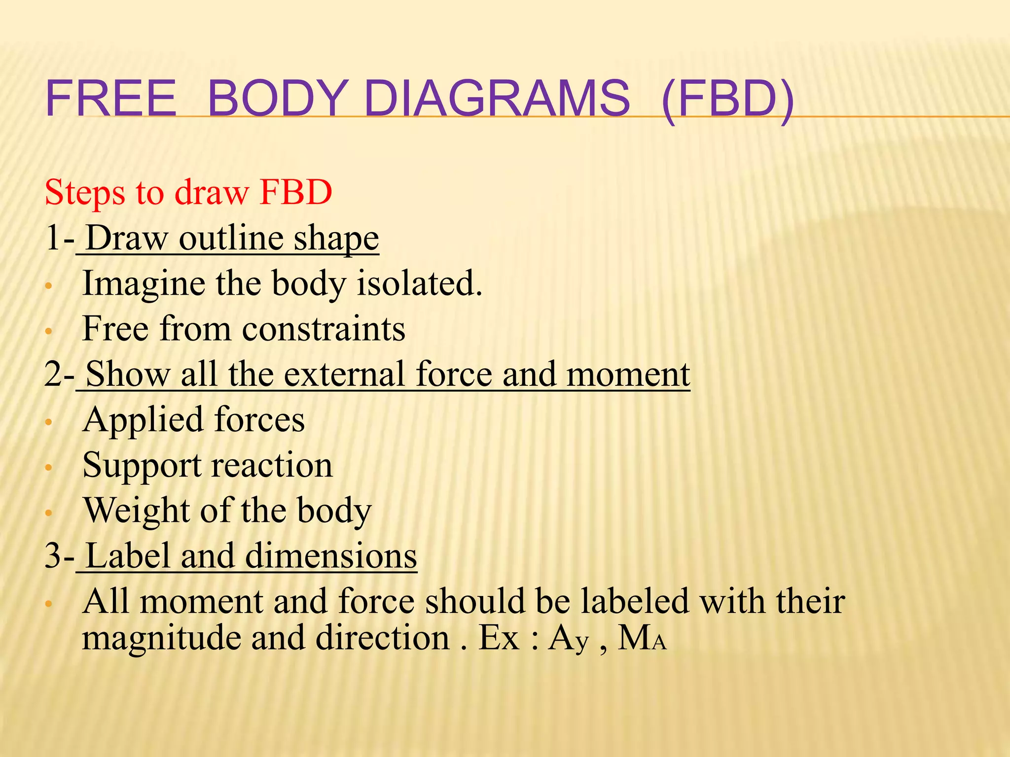
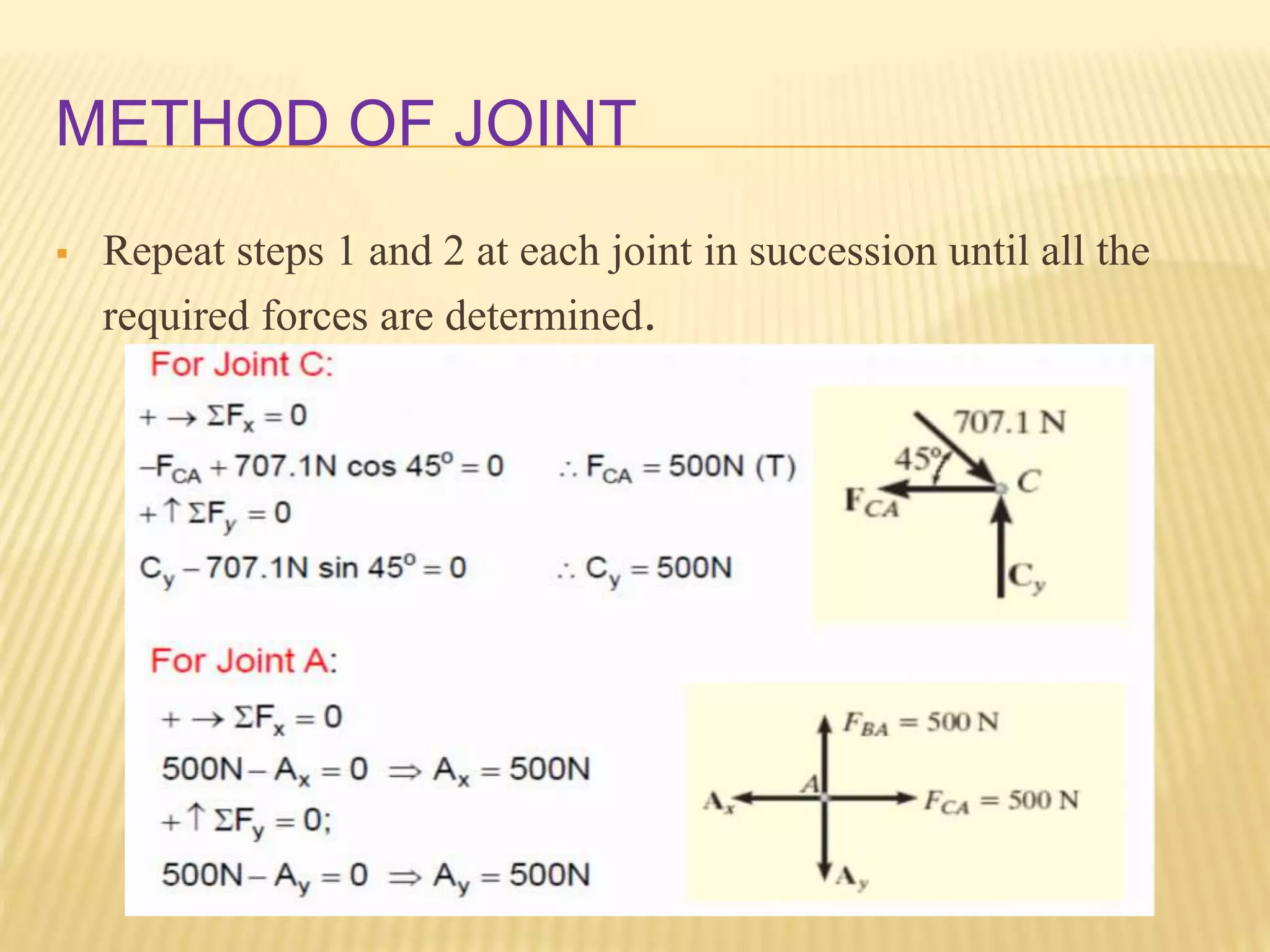
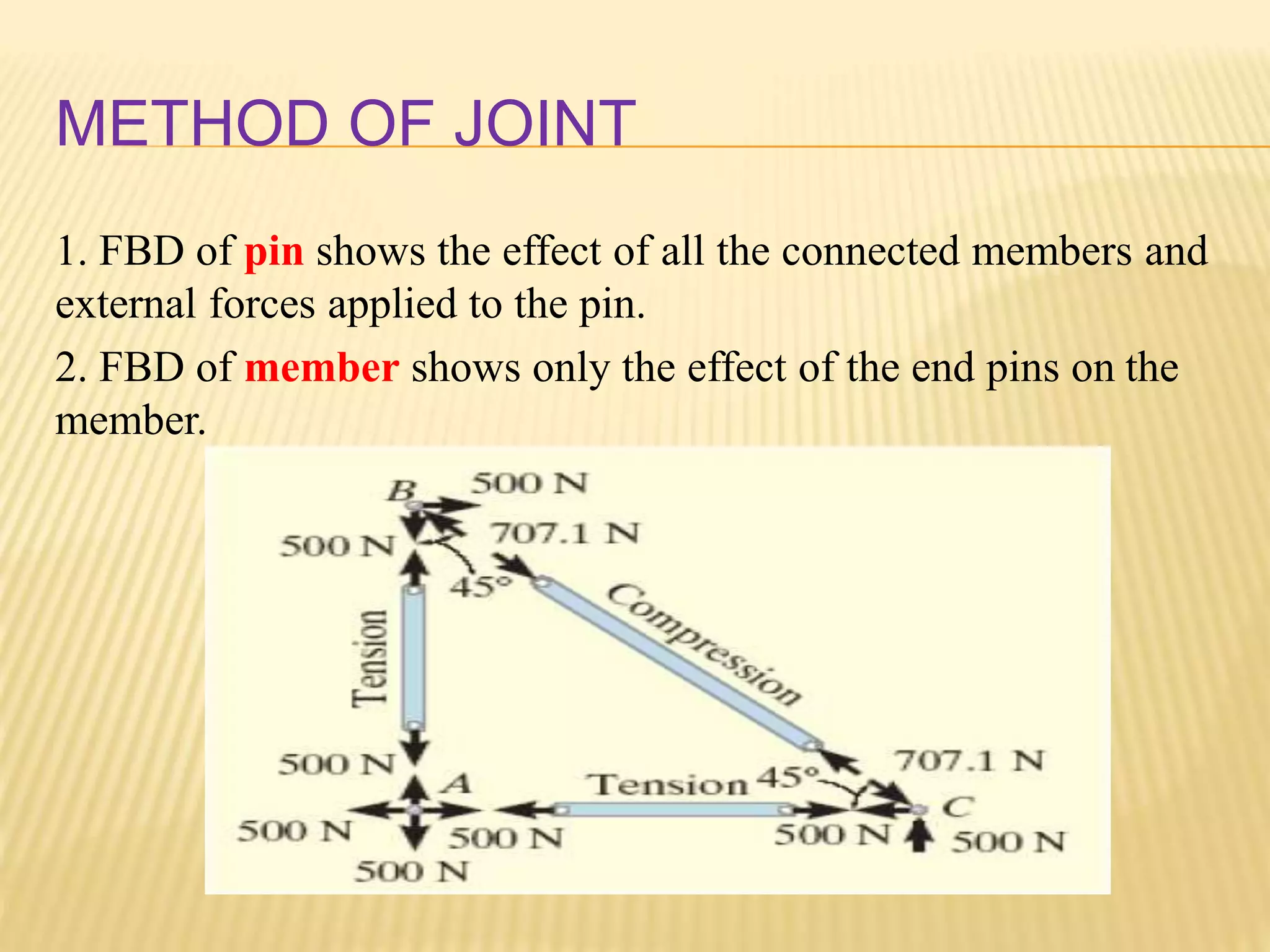
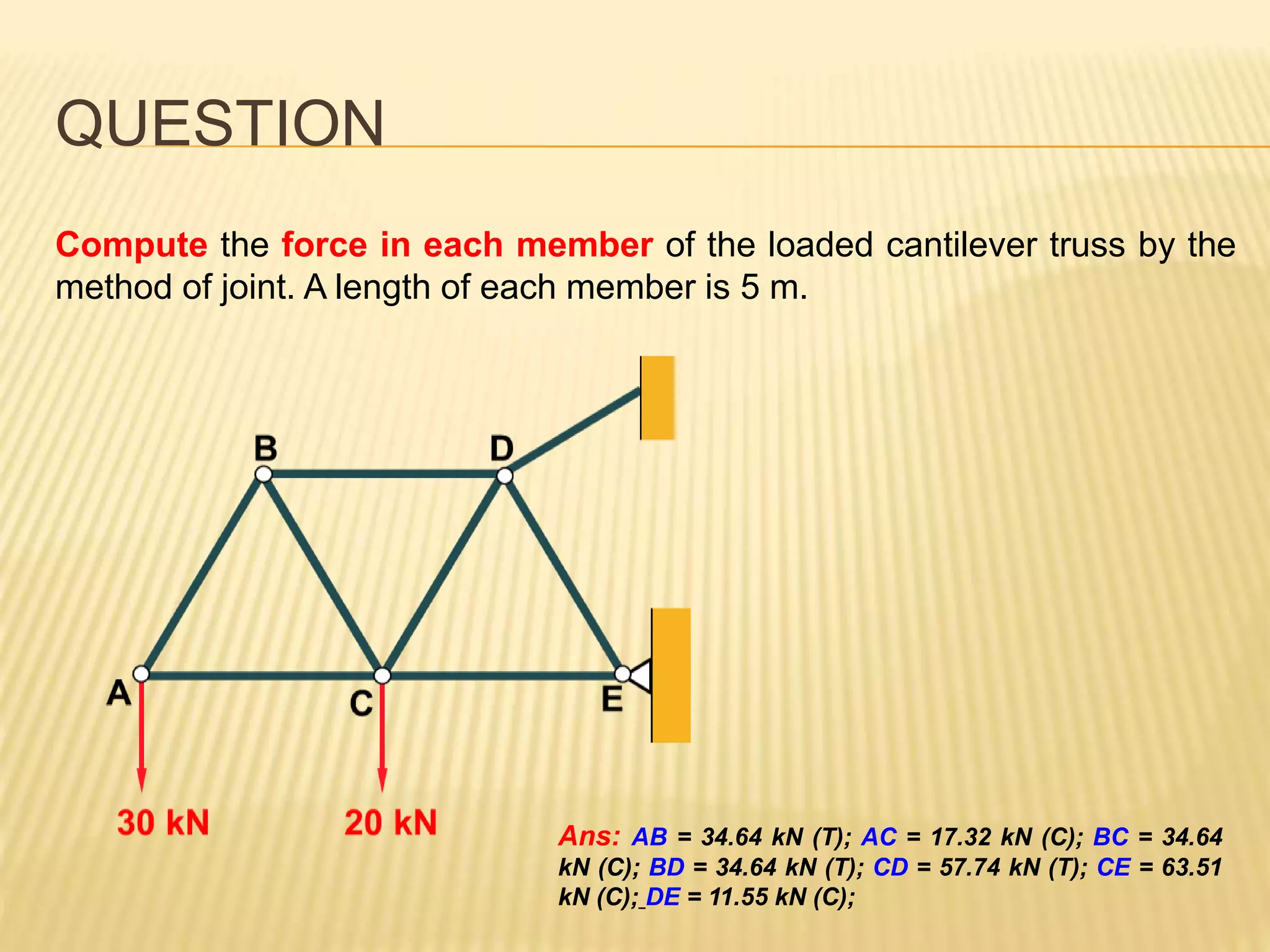
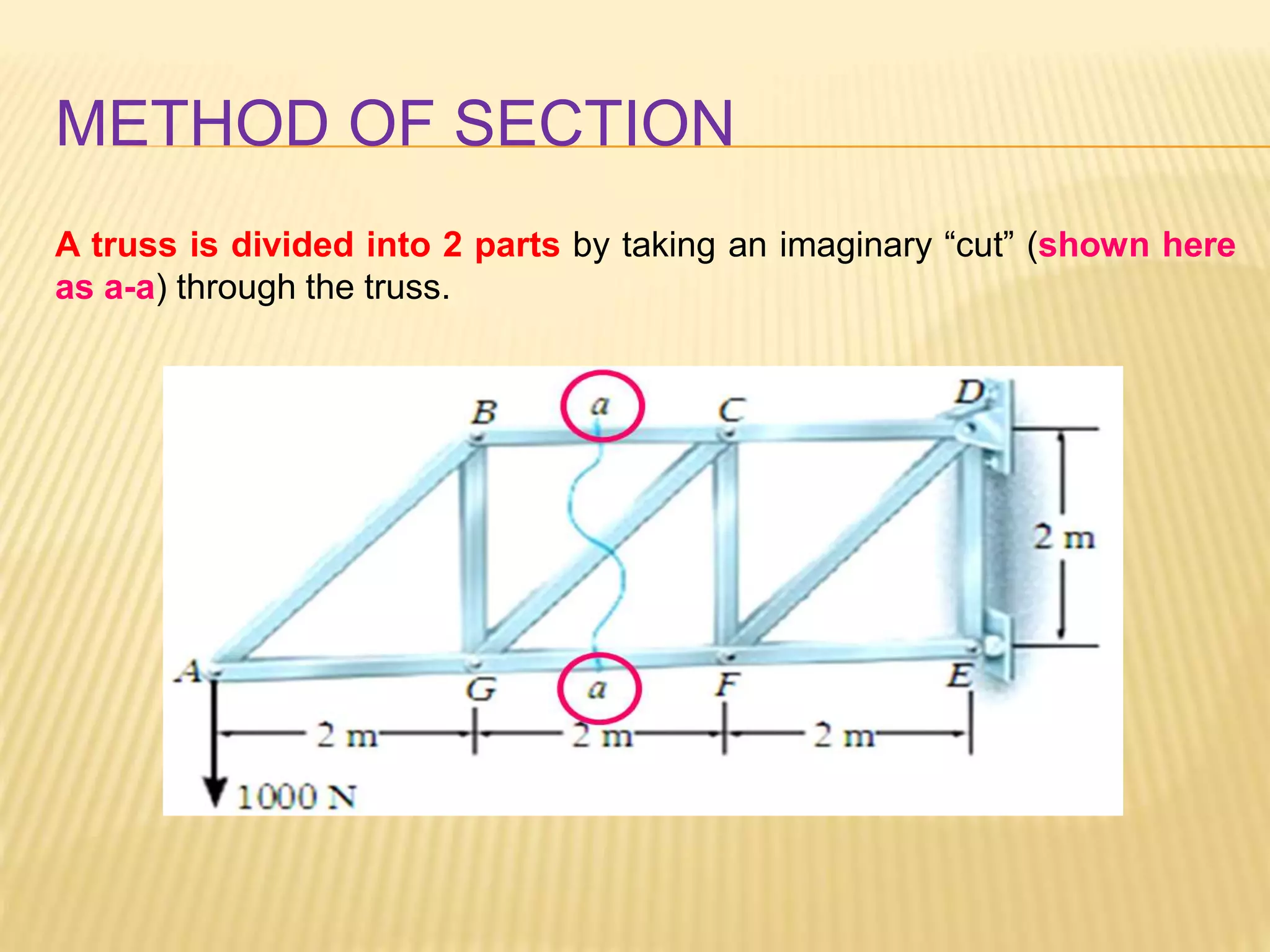
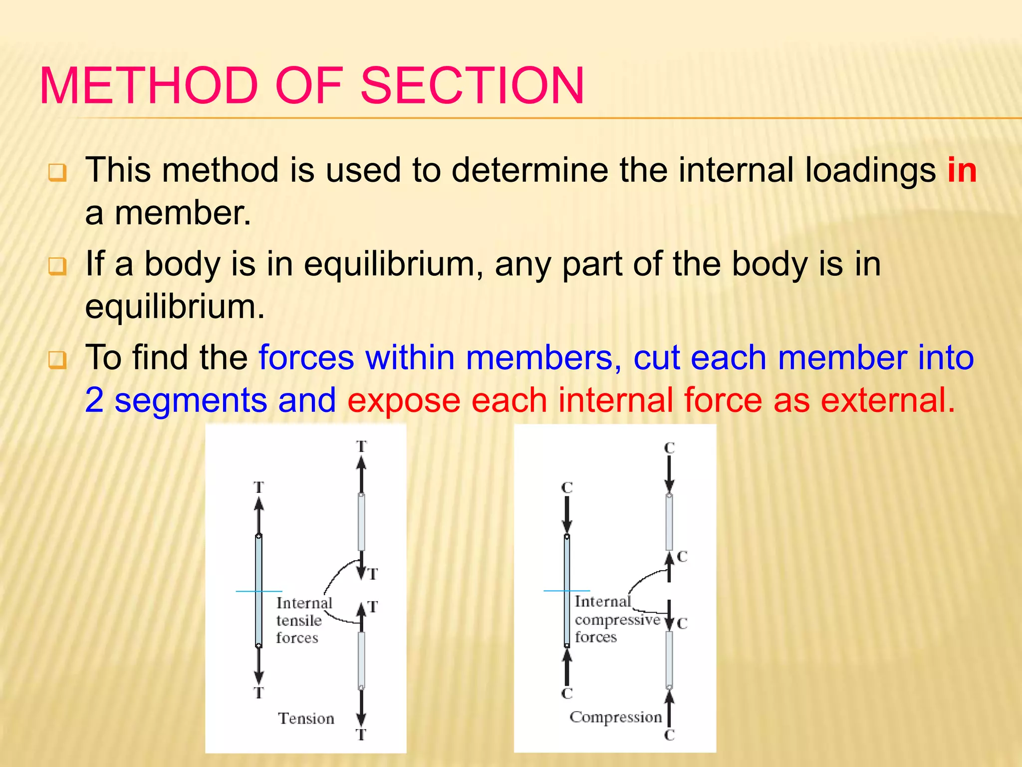
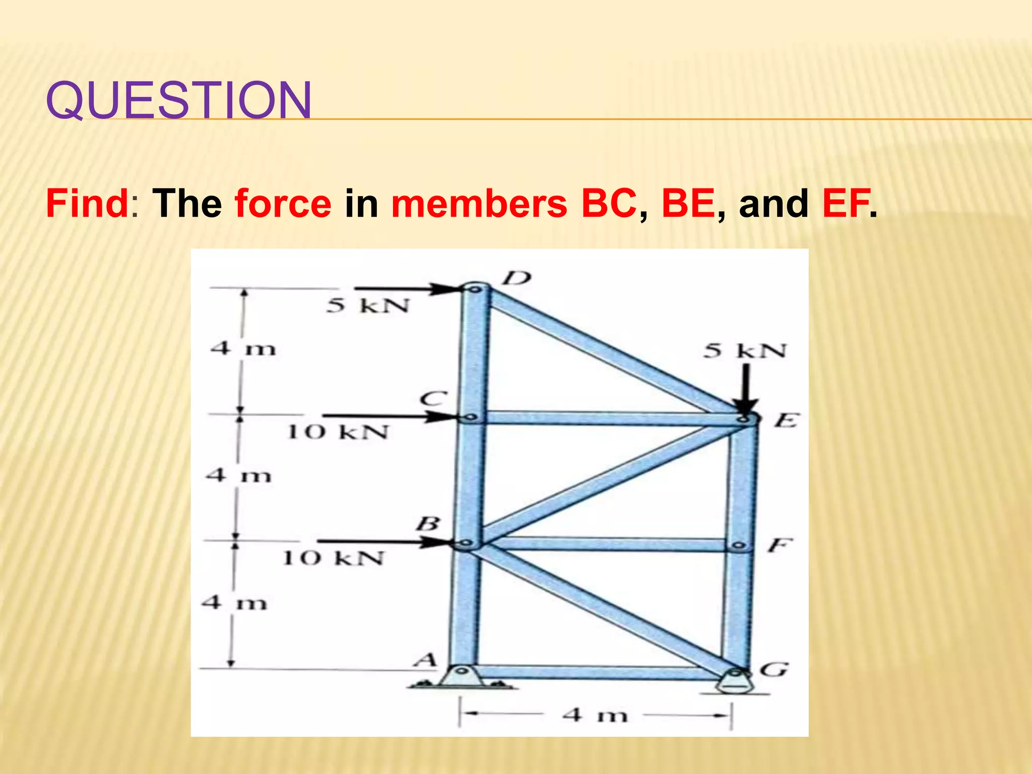
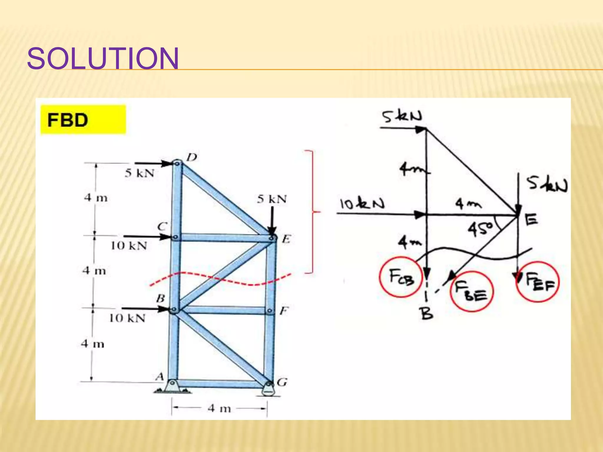
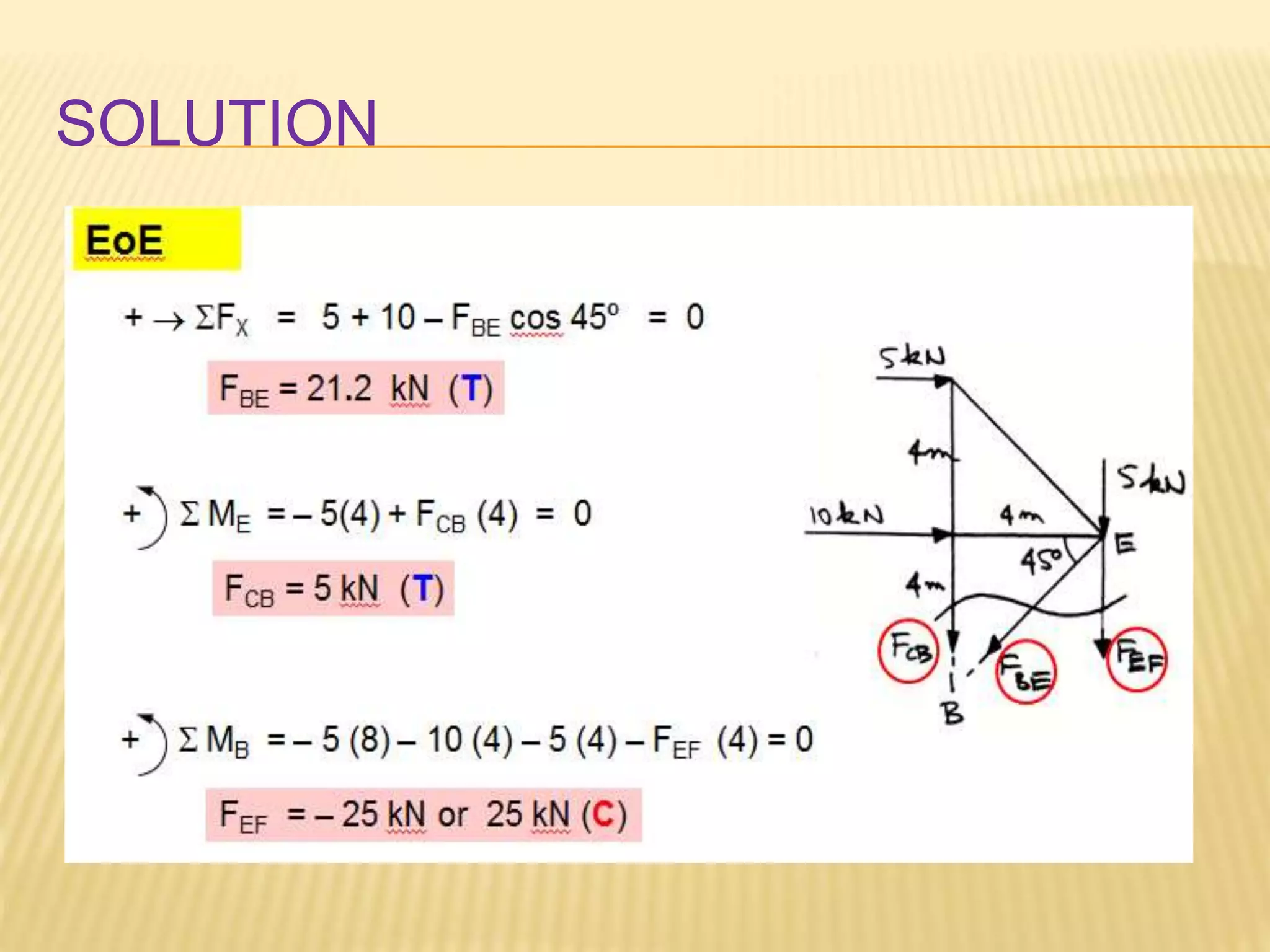
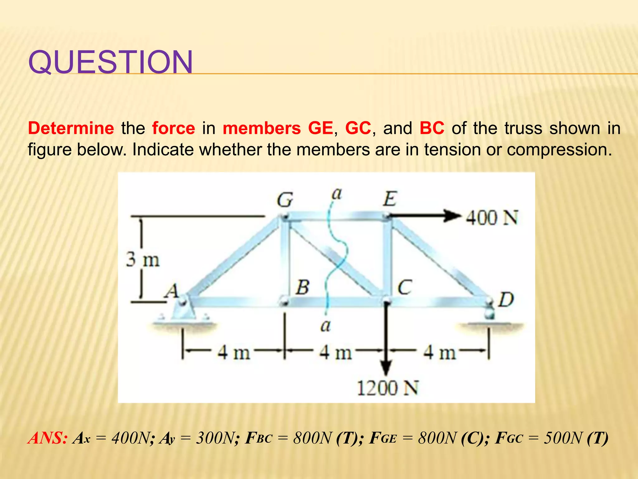
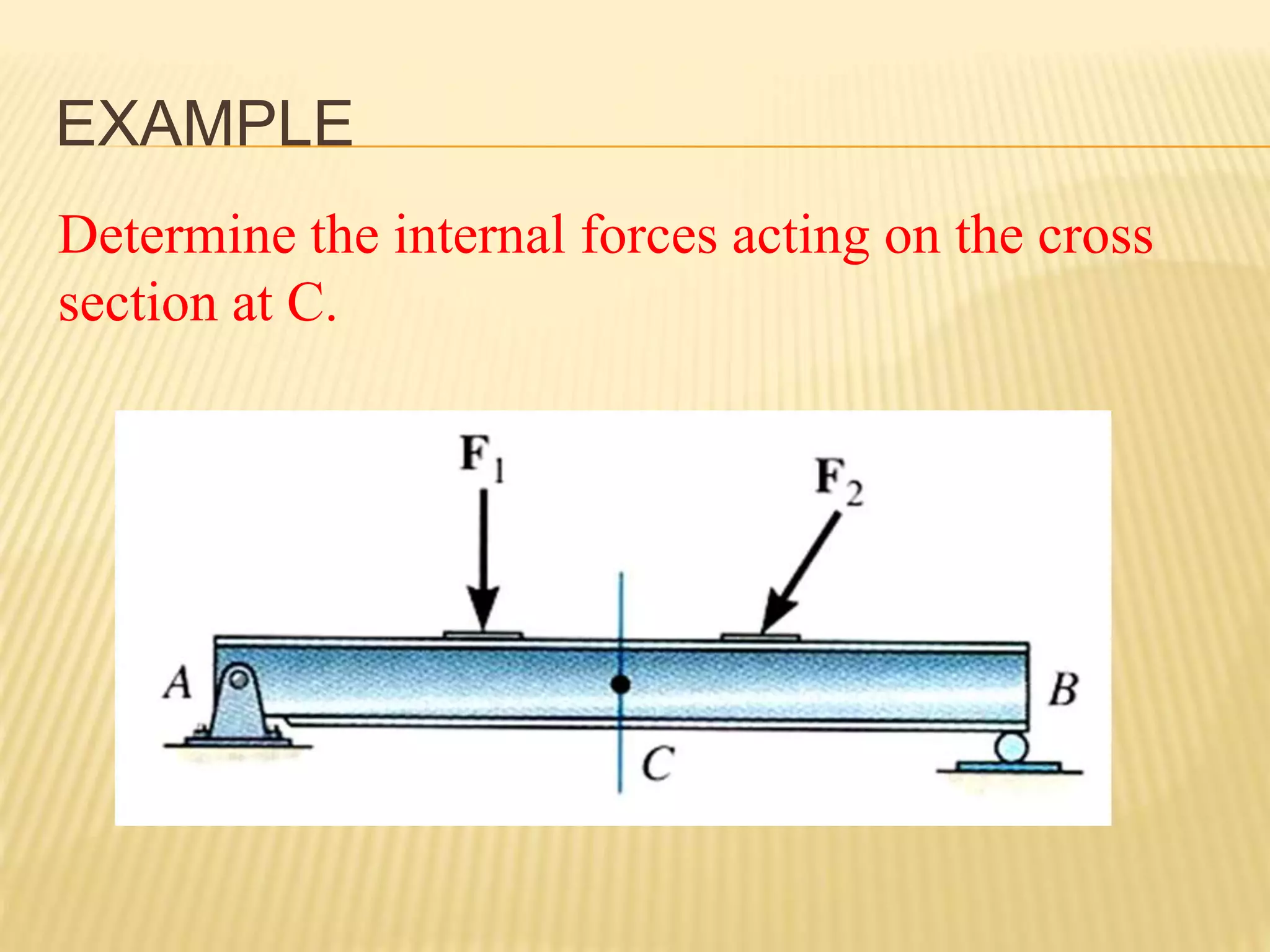
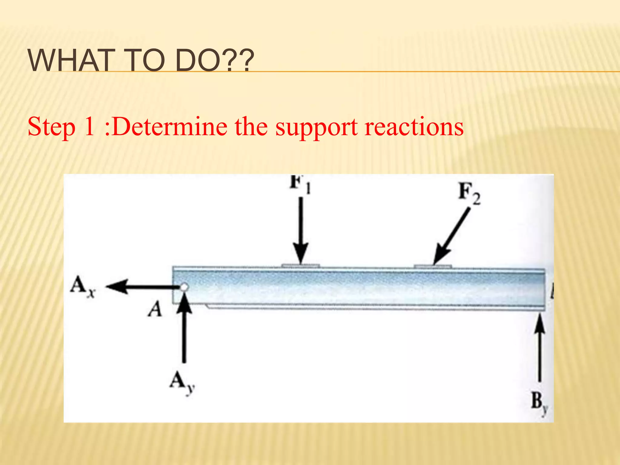
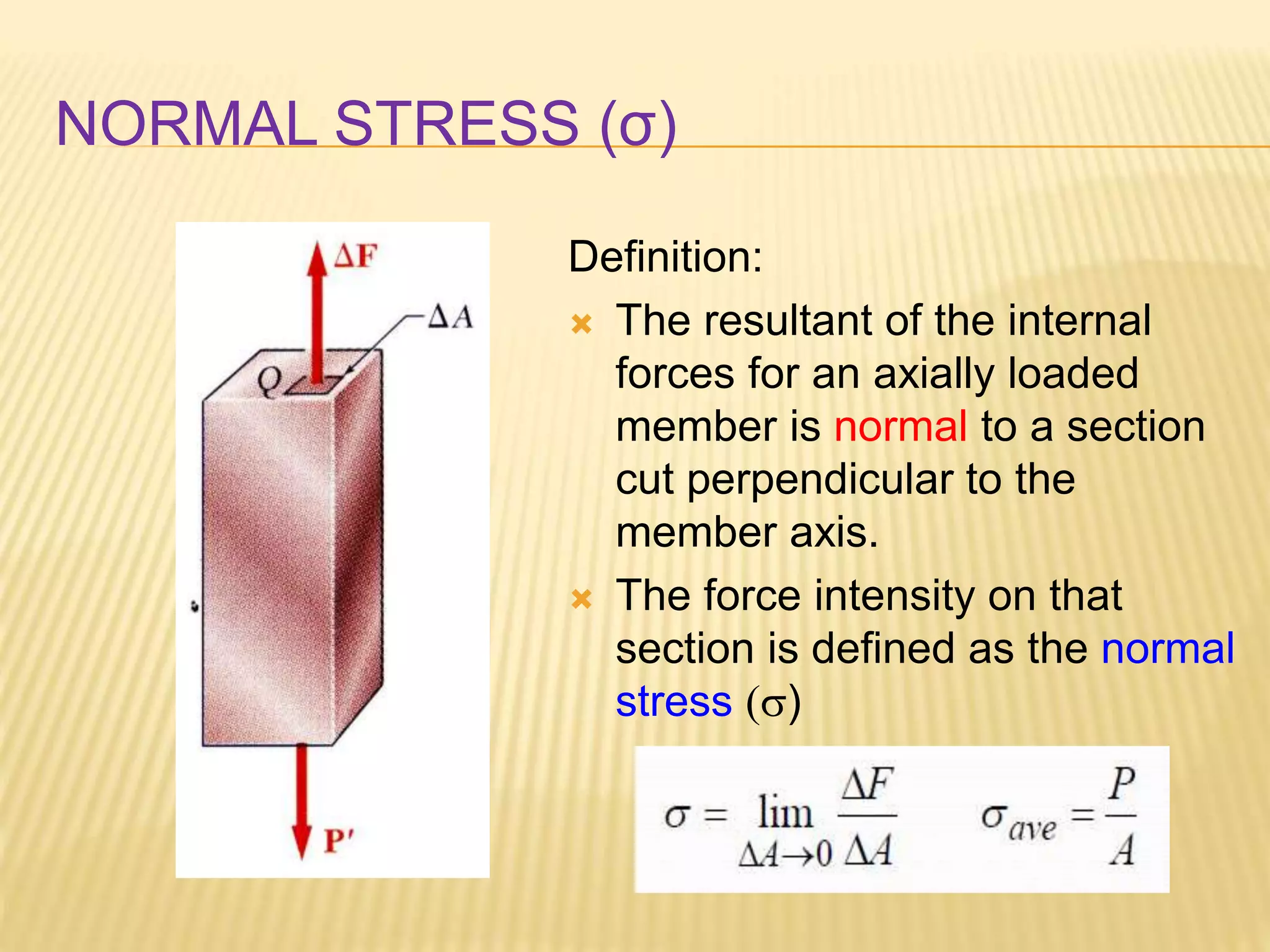
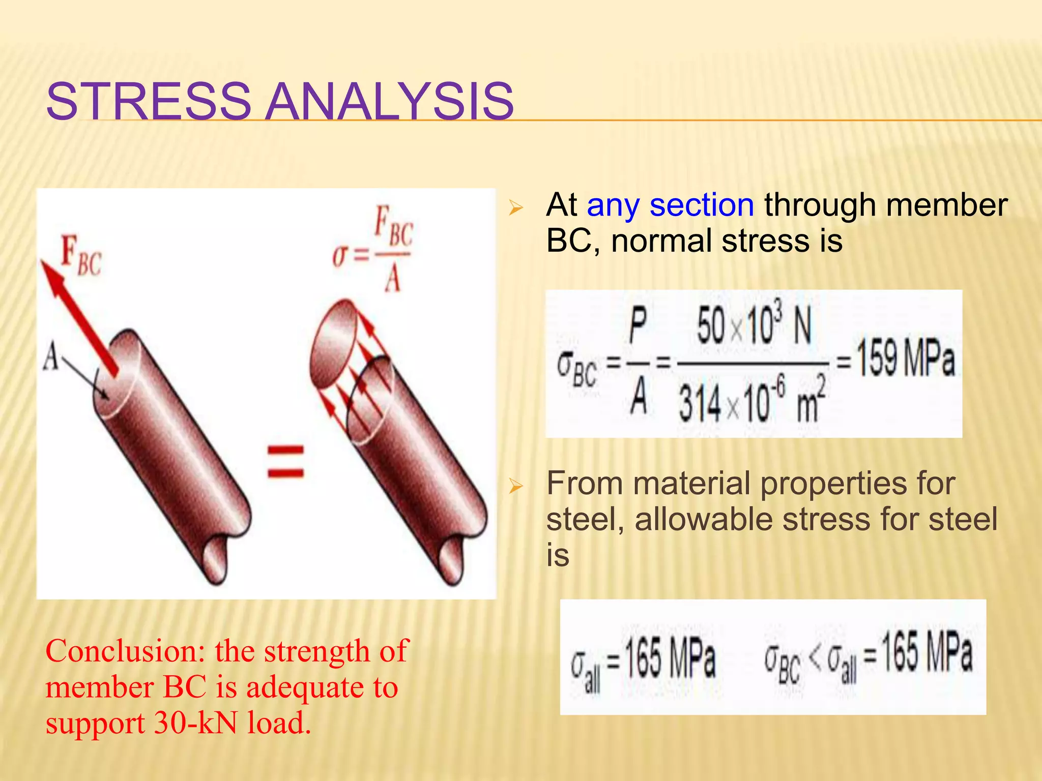
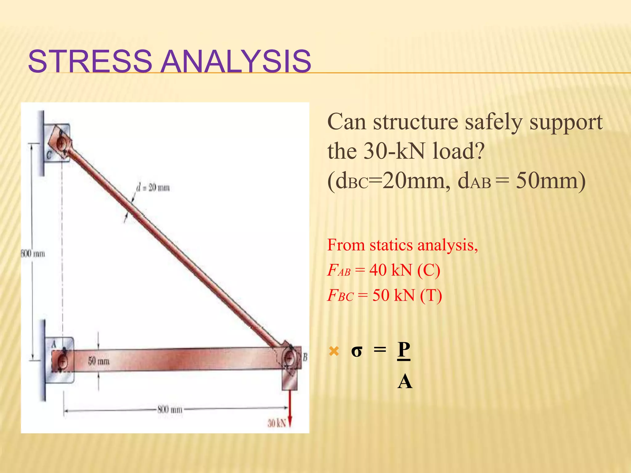
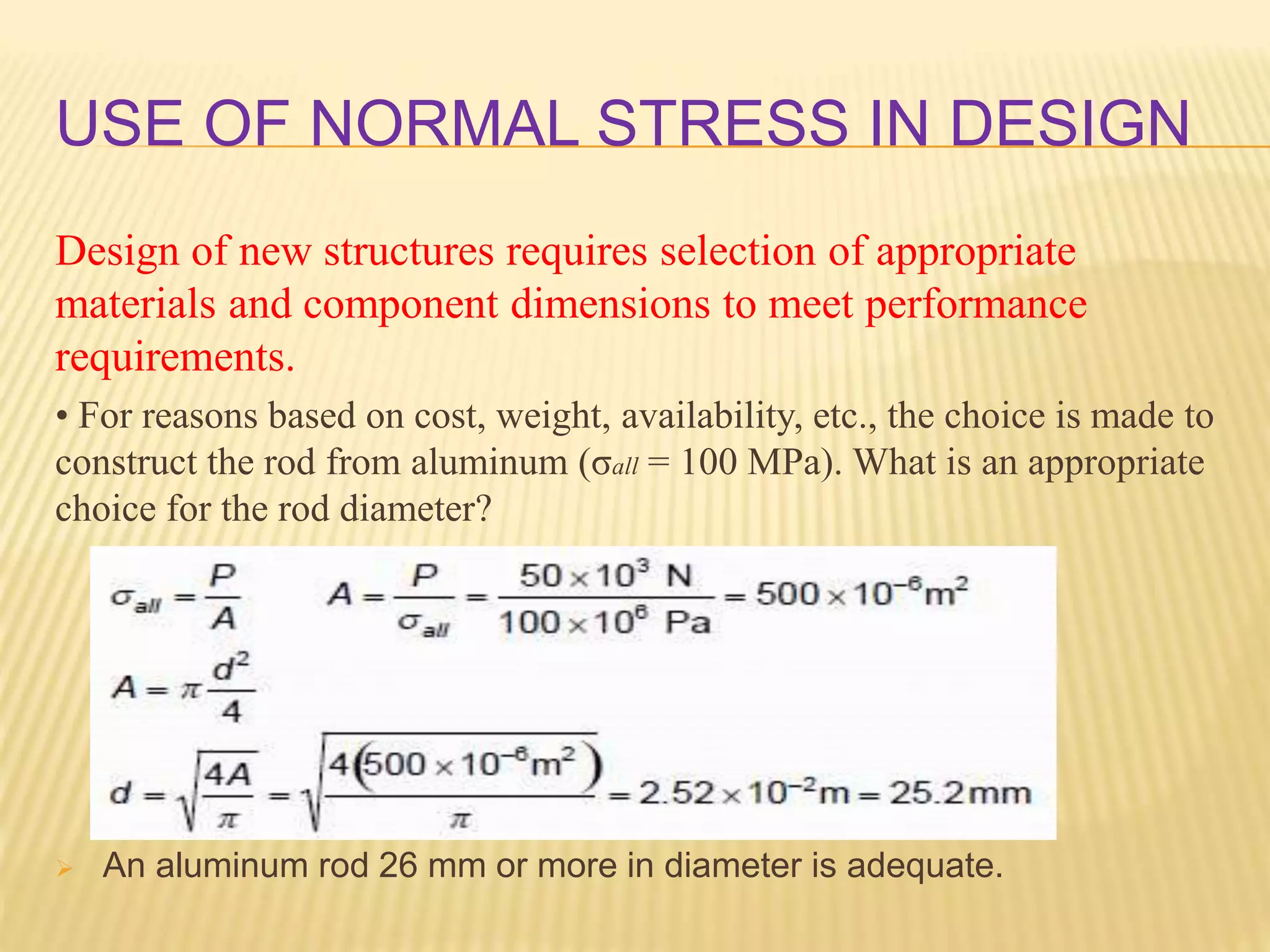
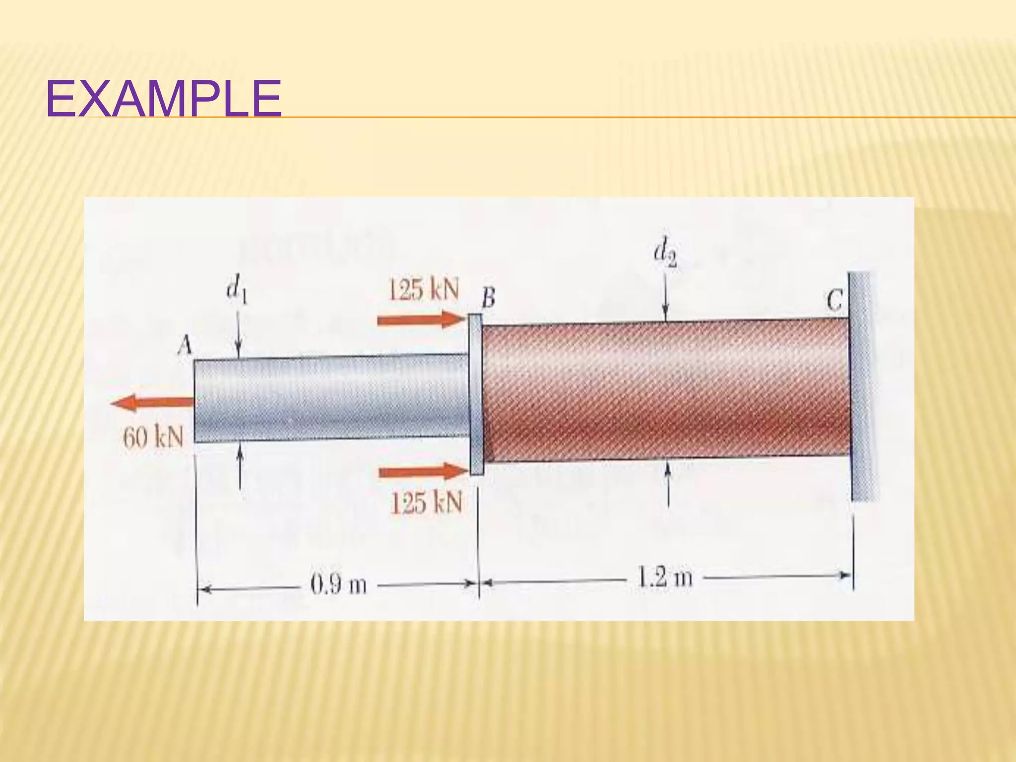
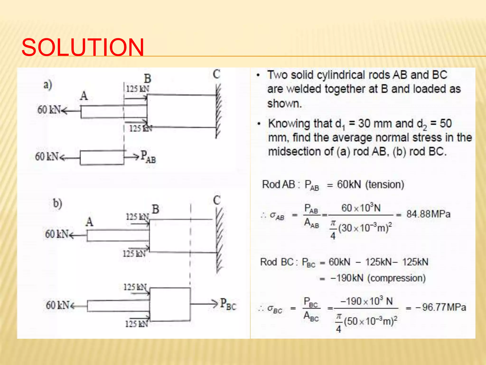
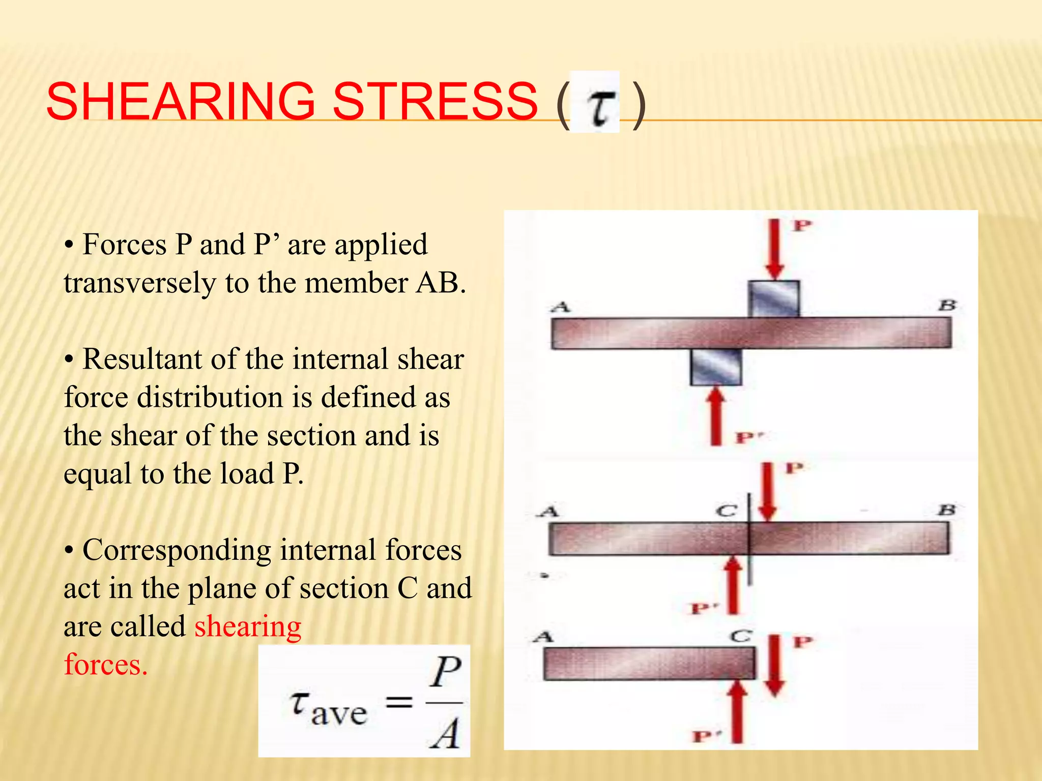
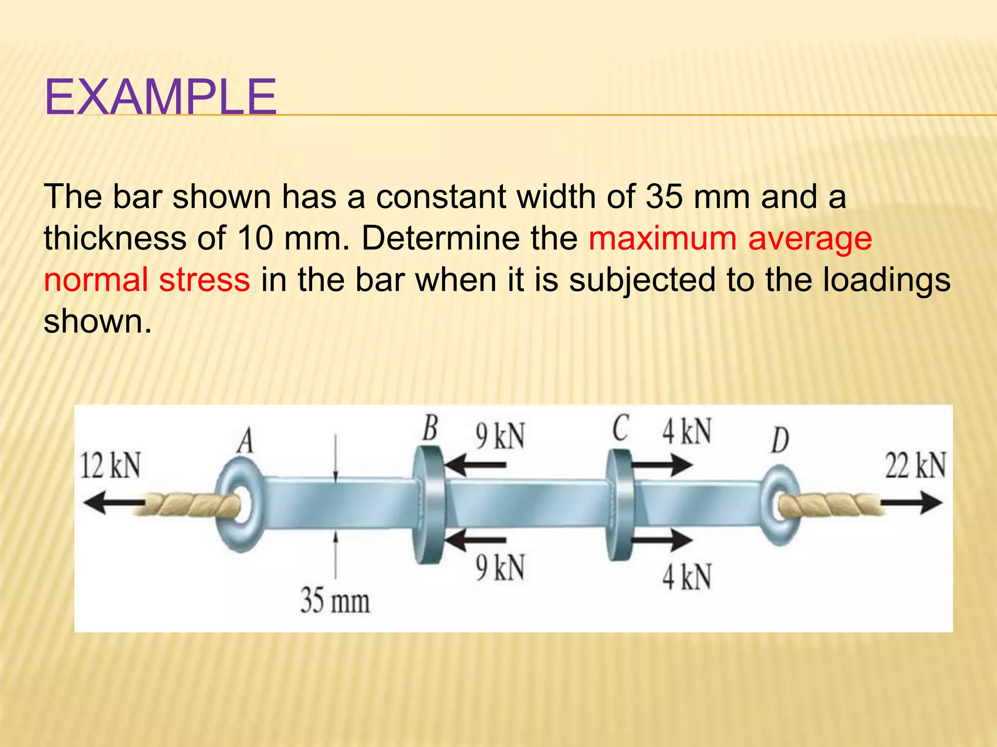
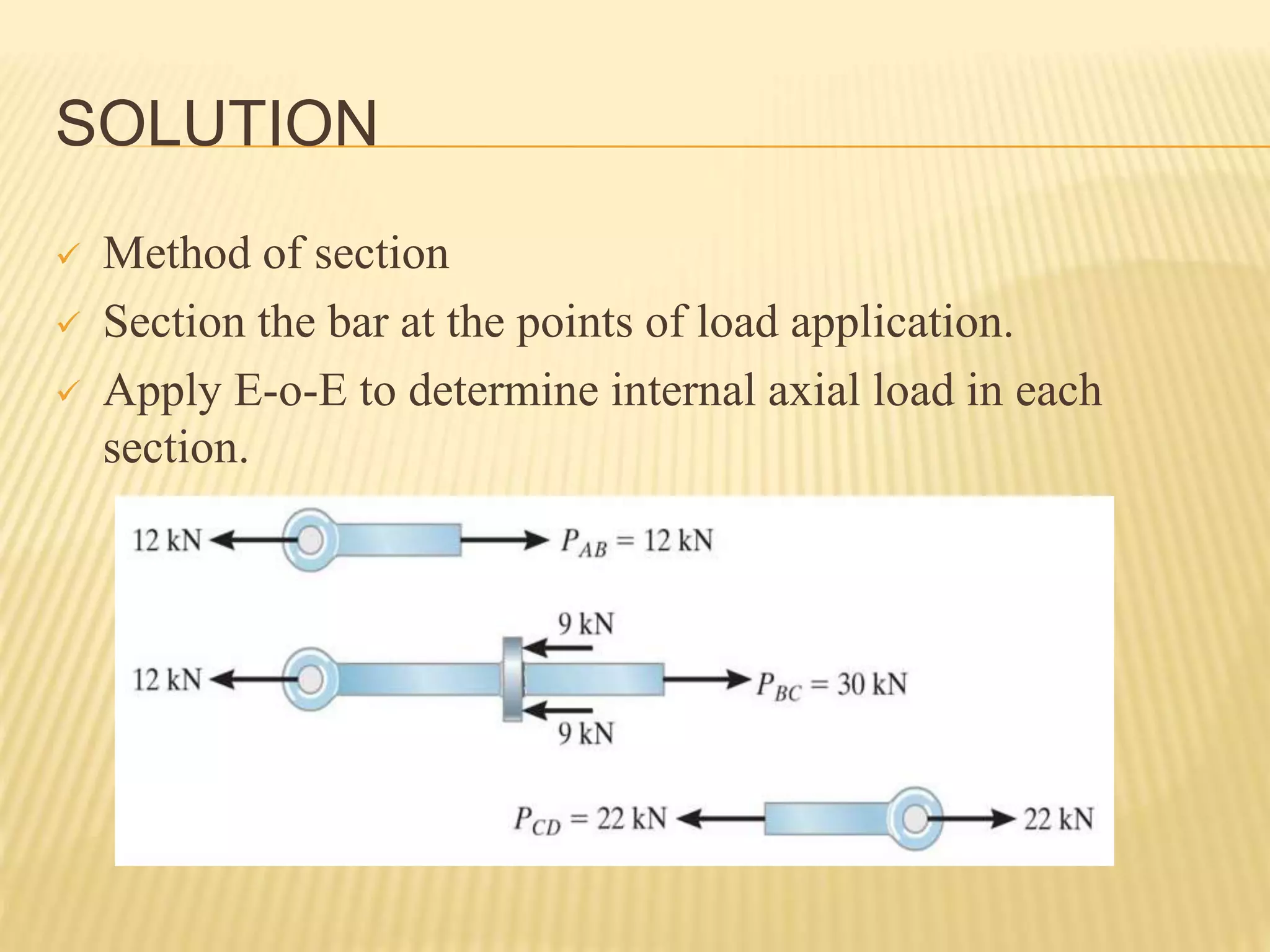
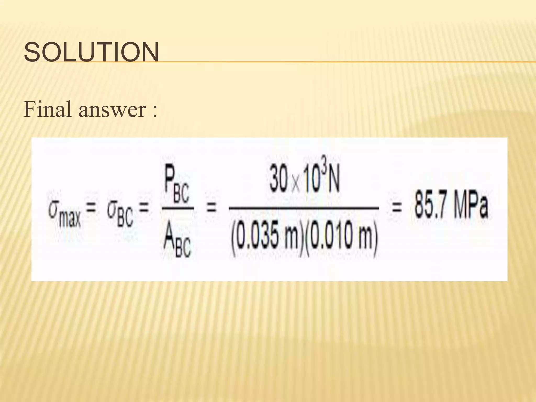
CHAPTER 1
INTRODUCTION: CONCEPT OF
STRESS
Super Material
 Lee Jia Yi
 Salma Elshaikh
 Nazhreen bin Azlan
 Norfiona Binti Rosli
REVIEW OF STATICS
 Prefixes and Units
 Type of support reaction
 Force Resolution : x-y components
 Addition of Force
 Moment of a Force
 Free Body Diagram
 Structural Analysis : i) Method of Joint
ii) Method of Section
STRESS IN MEMBERS OF A STRUCTURE
 Internal forces in structural members
NORMAL STRESS IN AXIAL BARS
Normal Stress
Shear Stress
PREFIXES
Exponential Form Prefix SI Symbol
Multiple
1000 000 000 109 Giga G
1000 000 106 Mega M
1000 103 kilo k
Submultiple
0.001 10-3 milli m
0.000 001 10-6 micro µ
0.000 000 001 10-9 nano n
UNITS
SI Metric units:
P = axial load (N)
A = cross-sectional area (m2)
σ = normal stress; N/ m2 = Pascal (Pa)
Prefixes:
1 kPa = 103 Pa = 103 N/ m2
1 MPa = 106 Pa = 106 N/ m2
1 GPa = 109 Pa = 109 N/ m2
U.S Customary Units:
P = axial load; lb or kilo pounds (kip)
A = cross-sectional area (in2)
σ = normal stress (psi or ksi)
SUPPORT REACTION
- The surface forces that develop at the supports or
points contact between bodies are called
reactions.
- There are few types of support reactions that we
learned before.
TYPES OF SUPPORT REACTION
APPLICATION OF SUPPORT REACTION
The cable exerts
a force on the
bracket in the
direction of the
cable.
APPLICATION OF SUPPORT REACTION
The rocker support
for this bridge
girder allows
horizontal
movement so the
bridge is free to
expand and contract
due to temperature.
APPLICATION OF SUPPORT REACTION
This concrete girder
rests on the ledge that
is assumed to act as a
smooth contacting
surface.
APPLICATION OF SUPPORT REACTION
This utility
building is pin
supported at the
top of the column.
APPLICATION OF SUPPORT REACTION
FORCES RESOLUTION: RECTANGULAR
COMPONENTS
It is easier if the force is
resolve into two
components, called
rectangular
components.
EXAMPLE
Resolve forces into
x-y components:
F1x = 600 N cos 30º
F1y = 600 N sin 30º
F2x = 400 N sin 45º
F2y = 400 N cos 45º
ADDITION OF FORCES
o Summation of all the forces in the x-component
and y-component.
o + Fx = ΣFx
o + Fy = Σfy
** Remember to consider the direction of the forces
 x-component - left : -ve
right: +ve
 y-component - downward: -ve
upward : +ve
EXAMPLE
Adding components:
+ FRx = ΣFx
FRx = F1x + F2x
= 600N cos30o +(- 400Nsin45o)
= 236.8N
+ FRy = Σfy
FRy =F1y + F2y
= 600N sin30o + 400N cos45o
=582.8N
MOMENT OF A FORCE
 Moment (M) of a force about a point provides a
measure of the tendency for rotation (also called a
torque).
MOMENT OF A FORCE
 The magnitude of the moment is Mo = F d.
where d is the perpendicular distance from point O to the line of
action of force F.
The direction of Mo is either clockwise or counter-clockwise,
depending on the tendency for rotation.
EXAMPLE
A 400 N force is applied to the frame and θ= 20°.
Find the moment of the force at A.
SOLUTION
•Resolve the given force into x and y components.
•Determine MA.
+ Fy = - 400 cos 20°N
+ Fx = - 400 sin 20° N
+ MA = +(400 cos 20°N)(2m) + (400 sin20°N)(3m)
= +1160 N·m CCW
FREE BODY DIAGRAMS (FBD)
Steps to draw FBD
1- Draw outline shape
• Imagine the body isolated.
• Free from constraints
2- Show all the external force and moment
• Applied forces
• Support reaction
• Weight of the body
3- Label and dimensions
• All moment and force should be labeled with their
magnitude and direction . Ex : Ay , MA
EXAMPLES
TRUSSES
TRUSSES
 Forces in the members are called Internal Forces.
 External force members are including support
reaction.
 2 force members : Tension (T)
Compression (C)
STRUCTURAL ANALYSIS OF TRUSS
Procedure for analysis
1. Draw FBD showing all the external force
2. Apply condition of equilibrium ∑ M = 0 ; ∑ Fx = 0 ;
∑ Fy = 0.
3. Joint method (every member)
4. Section method (some member)
5. Draw FBD for every partials member.
6. Apply ∑ Fx = 0 ; ∑ Fy = 0
Compression Tension
Compressive force Tensile force
EXAMPLE
Determine the
reactions at A and C,
and the force in each
member of the truss.
Indicate whether the
members are in
tension or
compression.
METHOD OF JOINT
Step 1 for analysis
- Draw FBD for the member around joints at least 1 known and 2
unknowns.
- This includes all external forces (including support reactions) as
well as the forces acting in the members.
- Determine the correct sense of the member. Assume that all
unknown member forces act in tension (pulling the pin) unless
you can determine by inspection that the forces are compression
loads.
- Orient the x & y axes.
METHOD OF JOINT
METHOD OF JOINT
Step 2 : Apply equations of equilibrium,  FX
= 0 and  FY = 0, to determine the
unknown(s).
**If the answer is +VE, then the assumed
direction (tension) is correct, otherwise it is in
the opposite direction (compression).
METHOD OF JOINT
METHOD OF JOINT
 Repeat steps 1 and 2 at each joint in succession until all the
required forces are determined.
METHOD OF JOINT
1. FBD of pin shows the effect of all the connected members and
external forces applied to the pin.
2. FBD of member shows only the effect of the end pins on the
member.
QUESTION
Compute the force in each member of the loaded cantilever truss by the
method of joint. A length of each member is 5 m.
Ans: AB = 34.64 kN (T); AC = 17.32 kN (C); BC = 34.64
kN (C); BD = 34.64 kN (T); CD = 57.74 kN (T); CE = 63.51
kN (C); DE = 11.55 kN (C);
METHOD OF SECTION
A truss is divided into 2 parts by taking an imaginary “cut” (shown here
as a-a) through the truss.
METHOD OF SECTION
 This method is used to determine the internal loadings in
a member.
 If a body is in equilibrium, any part of the body is in
equilibrium.
 To find the forces within members, cut each member into
2 segments and expose each internal force as external.
QUESTION
Find: The force in members BC, BE, and EF.
SOLUTION
SOLUTION
QUESTION
Determine the force in members GE, GC, and BC of the truss shown in
figure below. Indicate whether the members are in tension or compression.
ANS: Ax = 400N; Ay = 300N; FBC = 800N (T); FGE = 800N (C); FGC = 500N (T)
INTERNAL FORCES DEVELOPED IN
STRUCTURAL MEMBERS
Significance :
 The design of any structural member requires that
the material used is able to resist the loading acting
on that member.
 That means, finding the forces acting within the
member to make sure the material can resist those
loads.
 These internal loadings can be determined by the
method of sections.
EXAMPLE
Determine the internal forces acting on the cross
section at C.
WHAT TO DO??
Step 1 :Determine the support reactions
WHAT TO DO??
Step 2: Cut beam at C and draw FBD on one of the halves of the
beam. This FBD will include the internal forces acting at C.
Step 3: Apply equations of equilibrium to solve for these
unknowns.
SEGMENT SIGN CONVENTION
The loads on the left and right sides of the section are
equal in magnitude but opposite in direction. This is
because when the two sides are reconnected, the net
loads are zero at the section.
PROCEDURE FOR ANALYSIS
1. Determine support reactions or joint forces you
need by drawing a FBD of the entire structure and
solving for the unknown reactions.
2. Section at the place where you need to determine
the internal forces. Then, decide which resulting
section will be easier to analyze (usually the segment
having the least loads).
PROCEDURE FOR ANALYSIS
3. Draw a FBD of the section you want to analyze.
Remember to show the N, V, and M loads at the “cut” surface.
NOTE:
• Keep all distributed loadings, couple moments and forces
acting on the member in their exact locations.
• Only N, V and M act at the section.
• Determine their sense by inspection.
4. Apply equations of equilibrium (i.e. moment balance SM=0
and force balance SF=0) to the FBD drawn in step (3), and
solve for the unknown internal loads.
NOTE:
• Moments should be summed at the sectioned end.
• If negative result, the sense is the opposite.
NORMAL STRESS (σ)
Definition:
 The resultant of the internal
forces for an axially loaded
member is normal to a section
cut perpendicular to the
member axis.
 The force intensity on that
section is defined as the normal
stress (s)
STRESS ANALYSIS
 At any section through member
BC, normal stress is
 From material properties for
steel, allowable stress for steel
is
Conclusion: the strength of
member BC is adequate to
support 30-kN load.
STRESS ANALYSIS
Can structure safely support
the 30-kN load?
(dBC=20mm, dAB = 50mm)
From statics analysis,
FAB = 40 kN (C)
FBC = 50 kN (T)
 σ = P
A
USE OF NORMAL STRESS IN DESIGN
Design of new structures requires selection of appropriate
materials and component dimensions to meet performance
requirements.
• For reasons based on cost, weight, availability, etc., the choice is made to
construct the rod from aluminum (σall = 100 MPa). What is an appropriate
choice for the rod diameter?
 An aluminum rod 26 mm or more in diameter is adequate.
EXAMPLE
SOLUTION
SHEARING STRESS ( )
• Forces P and P’ are applied
transversely to the member AB.
• Resultant of the internal shear
force distribution is defined as
the shear of the section and is
equal to the load P.
• Corresponding internal forces
act in the plane of section C and
are called shearing
forces.
EXAMPLE
The bar shown has a constant width of 35 mm and a
thickness of 10 mm. Determine the maximum average
normal stress in the bar when it is subjected to the loadings
shown.
SOLUTION
 Method of section
 Section the bar at the points of load application.
 Apply E-o-E to determine internal axial load in each
section.
SOLUTION
Final answer :
Video
Time…
Lets us
solve questions
together…
Thank
You …

Chapter1 ME slid show (2).pptx

  • 1.
    CHAPTER 1 INTRODUCTION: CONCEPTOF STRESS Super Material  Lee Jia Yi  Salma Elshaikh  Nazhreen bin Azlan  Norfiona Binti Rosli
  • 2.
    REVIEW OF STATICS Prefixes and Units  Type of support reaction  Force Resolution : x-y components  Addition of Force  Moment of a Force  Free Body Diagram  Structural Analysis : i) Method of Joint ii) Method of Section
  • 3.
    STRESS IN MEMBERSOF A STRUCTURE  Internal forces in structural members NORMAL STRESS IN AXIAL BARS Normal Stress Shear Stress
  • 4.
    PREFIXES Exponential Form PrefixSI Symbol Multiple 1000 000 000 109 Giga G 1000 000 106 Mega M 1000 103 kilo k Submultiple 0.001 10-3 milli m 0.000 001 10-6 micro µ 0.000 000 001 10-9 nano n
  • 5.
    UNITS SI Metric units: P= axial load (N) A = cross-sectional area (m2) σ = normal stress; N/ m2 = Pascal (Pa) Prefixes: 1 kPa = 103 Pa = 103 N/ m2 1 MPa = 106 Pa = 106 N/ m2 1 GPa = 109 Pa = 109 N/ m2 U.S Customary Units: P = axial load; lb or kilo pounds (kip) A = cross-sectional area (in2) σ = normal stress (psi or ksi)
  • 6.
    SUPPORT REACTION - Thesurface forces that develop at the supports or points contact between bodies are called reactions. - There are few types of support reactions that we learned before.
  • 7.
  • 8.
    APPLICATION OF SUPPORTREACTION The cable exerts a force on the bracket in the direction of the cable.
  • 9.
    APPLICATION OF SUPPORTREACTION The rocker support for this bridge girder allows horizontal movement so the bridge is free to expand and contract due to temperature.
  • 10.
    APPLICATION OF SUPPORTREACTION This concrete girder rests on the ledge that is assumed to act as a smooth contacting surface.
  • 11.
    APPLICATION OF SUPPORTREACTION This utility building is pin supported at the top of the column.
  • 12.
  • 13.
  • 14.
  • 15.
    FORCES RESOLUTION: RECTANGULAR COMPONENTS Itis easier if the force is resolve into two components, called rectangular components.
  • 16.
    EXAMPLE Resolve forces into x-ycomponents: F1x = 600 N cos 30º F1y = 600 N sin 30º F2x = 400 N sin 45º F2y = 400 N cos 45º
  • 17.
    ADDITION OF FORCES oSummation of all the forces in the x-component and y-component. o + Fx = ΣFx o + Fy = Σfy ** Remember to consider the direction of the forces  x-component - left : -ve right: +ve  y-component - downward: -ve upward : +ve
  • 18.
    EXAMPLE Adding components: + FRx= ΣFx FRx = F1x + F2x = 600N cos30o +(- 400Nsin45o) = 236.8N + FRy = Σfy FRy =F1y + F2y = 600N sin30o + 400N cos45o =582.8N
  • 19.
    MOMENT OF AFORCE  Moment (M) of a force about a point provides a measure of the tendency for rotation (also called a torque).
  • 20.
    MOMENT OF AFORCE  The magnitude of the moment is Mo = F d. where d is the perpendicular distance from point O to the line of action of force F. The direction of Mo is either clockwise or counter-clockwise, depending on the tendency for rotation.
  • 21.
    EXAMPLE A 400 Nforce is applied to the frame and θ= 20°. Find the moment of the force at A.
  • 22.
    SOLUTION •Resolve the givenforce into x and y components. •Determine MA. + Fy = - 400 cos 20°N + Fx = - 400 sin 20° N + MA = +(400 cos 20°N)(2m) + (400 sin20°N)(3m) = +1160 N·m CCW
  • 23.
    FREE BODY DIAGRAMS(FBD) Steps to draw FBD 1- Draw outline shape • Imagine the body isolated. • Free from constraints 2- Show all the external force and moment • Applied forces • Support reaction • Weight of the body 3- Label and dimensions • All moment and force should be labeled with their magnitude and direction . Ex : Ay , MA
  • 24.
  • 25.
  • 26.
    TRUSSES  Forces inthe members are called Internal Forces.  External force members are including support reaction.  2 force members : Tension (T) Compression (C)
  • 27.
    STRUCTURAL ANALYSIS OFTRUSS Procedure for analysis 1. Draw FBD showing all the external force 2. Apply condition of equilibrium ∑ M = 0 ; ∑ Fx = 0 ; ∑ Fy = 0. 3. Joint method (every member) 4. Section method (some member) 5. Draw FBD for every partials member. 6. Apply ∑ Fx = 0 ; ∑ Fy = 0 Compression Tension Compressive force Tensile force
  • 28.
    EXAMPLE Determine the reactions atA and C, and the force in each member of the truss. Indicate whether the members are in tension or compression.
  • 29.
    METHOD OF JOINT Step1 for analysis - Draw FBD for the member around joints at least 1 known and 2 unknowns. - This includes all external forces (including support reactions) as well as the forces acting in the members. - Determine the correct sense of the member. Assume that all unknown member forces act in tension (pulling the pin) unless you can determine by inspection that the forces are compression loads. - Orient the x & y axes.
  • 30.
  • 31.
    METHOD OF JOINT Step2 : Apply equations of equilibrium,  FX = 0 and  FY = 0, to determine the unknown(s). **If the answer is +VE, then the assumed direction (tension) is correct, otherwise it is in the opposite direction (compression).
  • 32.
  • 33.
    METHOD OF JOINT Repeat steps 1 and 2 at each joint in succession until all the required forces are determined.
  • 34.
    METHOD OF JOINT 1.FBD of pin shows the effect of all the connected members and external forces applied to the pin. 2. FBD of member shows only the effect of the end pins on the member.
  • 35.
    QUESTION Compute the forcein each member of the loaded cantilever truss by the method of joint. A length of each member is 5 m. Ans: AB = 34.64 kN (T); AC = 17.32 kN (C); BC = 34.64 kN (C); BD = 34.64 kN (T); CD = 57.74 kN (T); CE = 63.51 kN (C); DE = 11.55 kN (C);
  • 36.
    METHOD OF SECTION Atruss is divided into 2 parts by taking an imaginary “cut” (shown here as a-a) through the truss.
  • 37.
    METHOD OF SECTION This method is used to determine the internal loadings in a member.  If a body is in equilibrium, any part of the body is in equilibrium.  To find the forces within members, cut each member into 2 segments and expose each internal force as external.
  • 38.
    QUESTION Find: The forcein members BC, BE, and EF.
  • 39.
  • 40.
  • 41.
    QUESTION Determine the forcein members GE, GC, and BC of the truss shown in figure below. Indicate whether the members are in tension or compression. ANS: Ax = 400N; Ay = 300N; FBC = 800N (T); FGE = 800N (C); FGC = 500N (T)
  • 42.
    INTERNAL FORCES DEVELOPEDIN STRUCTURAL MEMBERS Significance :  The design of any structural member requires that the material used is able to resist the loading acting on that member.  That means, finding the forces acting within the member to make sure the material can resist those loads.  These internal loadings can be determined by the method of sections.
  • 43.
    EXAMPLE Determine the internalforces acting on the cross section at C.
  • 44.
    WHAT TO DO?? Step1 :Determine the support reactions
  • 45.
    WHAT TO DO?? Step2: Cut beam at C and draw FBD on one of the halves of the beam. This FBD will include the internal forces acting at C. Step 3: Apply equations of equilibrium to solve for these unknowns.
  • 46.
    SEGMENT SIGN CONVENTION Theloads on the left and right sides of the section are equal in magnitude but opposite in direction. This is because when the two sides are reconnected, the net loads are zero at the section.
  • 47.
    PROCEDURE FOR ANALYSIS 1.Determine support reactions or joint forces you need by drawing a FBD of the entire structure and solving for the unknown reactions. 2. Section at the place where you need to determine the internal forces. Then, decide which resulting section will be easier to analyze (usually the segment having the least loads).
  • 48.
    PROCEDURE FOR ANALYSIS 3.Draw a FBD of the section you want to analyze. Remember to show the N, V, and M loads at the “cut” surface. NOTE: • Keep all distributed loadings, couple moments and forces acting on the member in their exact locations. • Only N, V and M act at the section. • Determine their sense by inspection. 4. Apply equations of equilibrium (i.e. moment balance SM=0 and force balance SF=0) to the FBD drawn in step (3), and solve for the unknown internal loads. NOTE: • Moments should be summed at the sectioned end. • If negative result, the sense is the opposite.
  • 49.
    NORMAL STRESS (σ) Definition: The resultant of the internal forces for an axially loaded member is normal to a section cut perpendicular to the member axis.  The force intensity on that section is defined as the normal stress (s)
  • 50.
    STRESS ANALYSIS  Atany section through member BC, normal stress is  From material properties for steel, allowable stress for steel is Conclusion: the strength of member BC is adequate to support 30-kN load.
  • 51.
    STRESS ANALYSIS Can structuresafely support the 30-kN load? (dBC=20mm, dAB = 50mm) From statics analysis, FAB = 40 kN (C) FBC = 50 kN (T)  σ = P A
  • 52.
    USE OF NORMALSTRESS IN DESIGN Design of new structures requires selection of appropriate materials and component dimensions to meet performance requirements. • For reasons based on cost, weight, availability, etc., the choice is made to construct the rod from aluminum (σall = 100 MPa). What is an appropriate choice for the rod diameter?  An aluminum rod 26 mm or more in diameter is adequate.
  • 53.
  • 54.
  • 55.
    SHEARING STRESS () • Forces P and P’ are applied transversely to the member AB. • Resultant of the internal shear force distribution is defined as the shear of the section and is equal to the load P. • Corresponding internal forces act in the plane of section C and are called shearing forces.
  • 56.
    EXAMPLE The bar shownhas a constant width of 35 mm and a thickness of 10 mm. Determine the maximum average normal stress in the bar when it is subjected to the loadings shown.
  • 57.
    SOLUTION  Method ofsection  Section the bar at the points of load application.  Apply E-o-E to determine internal axial load in each section.
  • 58.
  • 59.
  • 60.
  • 61.