This document discusses key concepts in radiotherapy dosage, including:
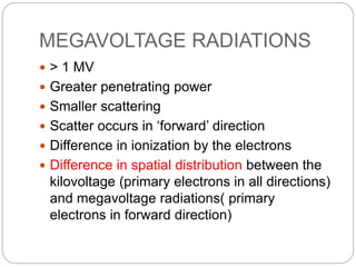
1. Surface dose and kilovoltage radiation were limiting factors, while megavoltage radiation allows deeper penetration with less scatter.
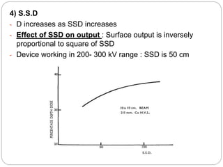
2. Primary radiation output depends on tube current, voltage, target material and distance from source, while scattered radiation depends on beam size, shape, and material properties.
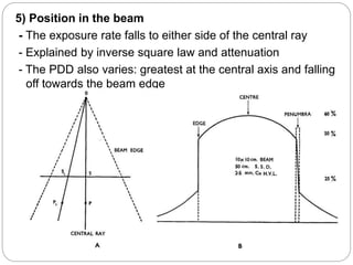
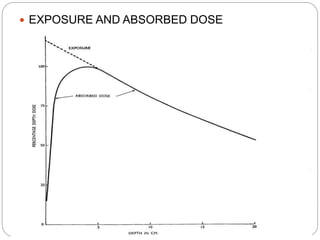
3. With megavoltage beams, electrons travel farther, depositing most energy at the end of their track and creating a "build up" where dose increases with depth before falling off due to inverse square law.