Downloaded 2,091 times
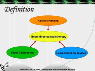
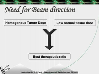
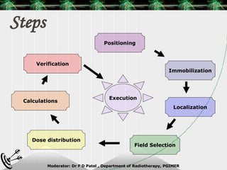
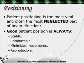

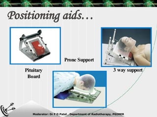
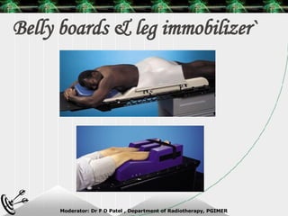
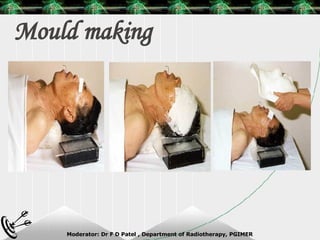
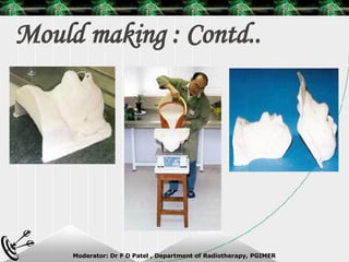
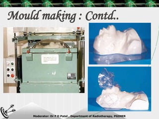


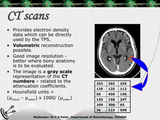
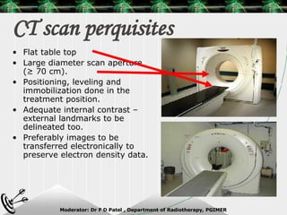
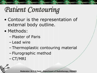


Beam directed radiotherapy aims to deliver a homogenous tumor dose while minimizing radiation to normal tissues. It involves careful patient positioning, immobilization, tumor localization, field selection, dose calculations, and verification. Key steps include using positioning aids and molds to reproducibly position the patient, imaging such as CT to delineate the tumor volume, contouring to define external body outlines, and dose calculations and verification to ensure accurate delivery.


![Arc therapy [autosaved] [autosaved]](https://cdn.slidesharecdn.com/ss_thumbnails/arctherapyautosavedautosaved-150423125828-conversion-gate01-thumbnail.jpg?width=640&height=640&fit=bounds)