Downloaded 444 times


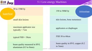


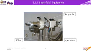
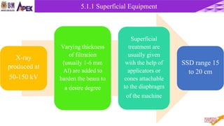


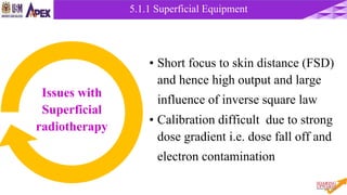


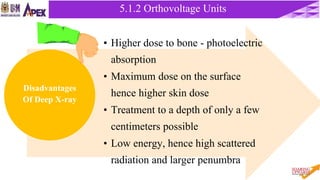


This document discusses radiotherapy equipment, including low-energy machines and external beam equipment such as superficial x-ray units, orthovoltage machines, telecurie units using radioactive cobalt-60 and cesium-137 sources, and linear accelerators. It describes the properties, production, applications and limitations of different radiotherapy machines. The document focuses in detail on cobalt-60 teletherapy units, explaining their photon energy, production method, source design and shielding, dose profile, and techniques to reduce penumbra.


