Download as PDF, PPTX


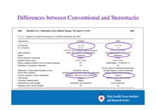
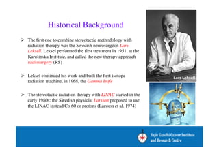
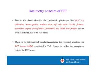

The document outlines the history, advancements, and recommendations for stereotactic radiosurgery (SRS) and stereotactic body radiation therapy (SBRT), highlighting the advantages of flattening filter free (FFF) beams, which allow for higher dose rates and reduced radiation exposure to surrounding tissues. It discusses the evolution of SRS/SBRT methods, including the use of linear accelerators and gamma knife technology, as well as dosimetric concerns associated with FFF beams. Additionally, the document provides recommendations from the AERB and AAPM Task Group regarding treatment protocols, simulation imaging, and effective dose calculation algorithms for implementing these advanced radiation therapies.


![Arc therapy [autosaved] [autosaved]](https://cdn.slidesharecdn.com/ss_thumbnails/arctherapyautosavedautosaved-150423125828-conversion-gate01-thumbnail.jpg?width=640&height=640&fit=bounds)


