Downloaded 1,029 times


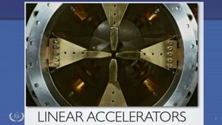
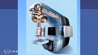

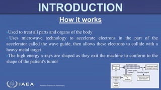

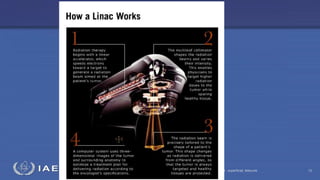


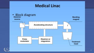
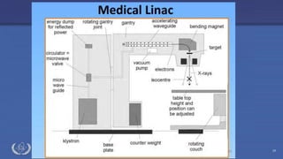
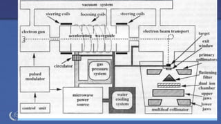
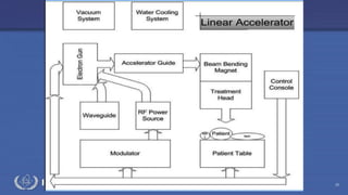
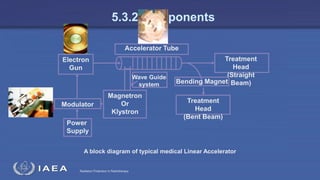
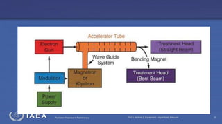

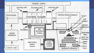
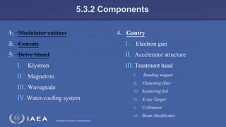
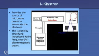
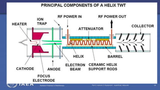
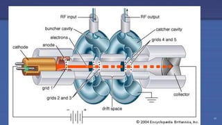
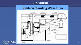
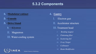


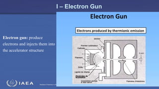
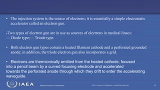
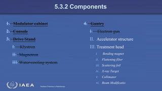
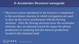
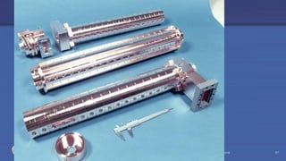
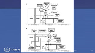
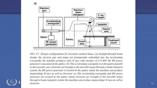
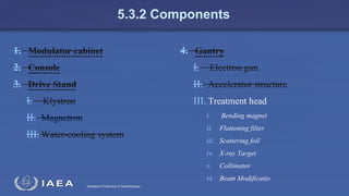
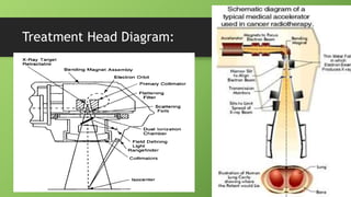
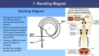
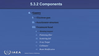
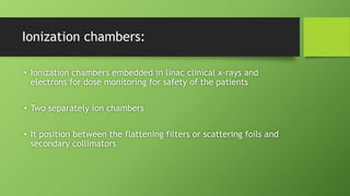

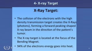

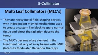
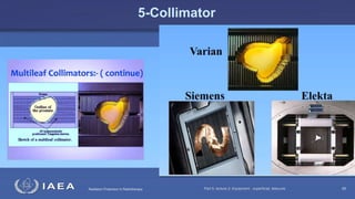


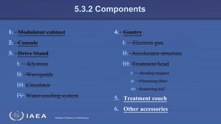

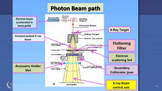
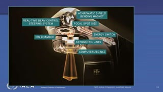
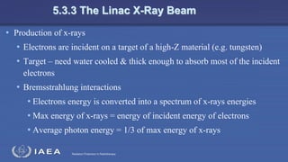
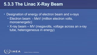
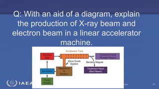

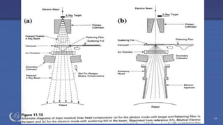


The document discusses the components and operation of a linear accelerator used for radiation therapy. It describes the key parts of a linear accelerator including the electron gun, accelerator structure, treatment head and how they work together to generate photon or electron beams for radiation treatment. The linear accelerator uses microwave technology to accelerate electrons which are then converted into x-ray or electron beams that can be aimed at a tumor from multiple angles using the rotating gantry.


