Downloaded 235 times


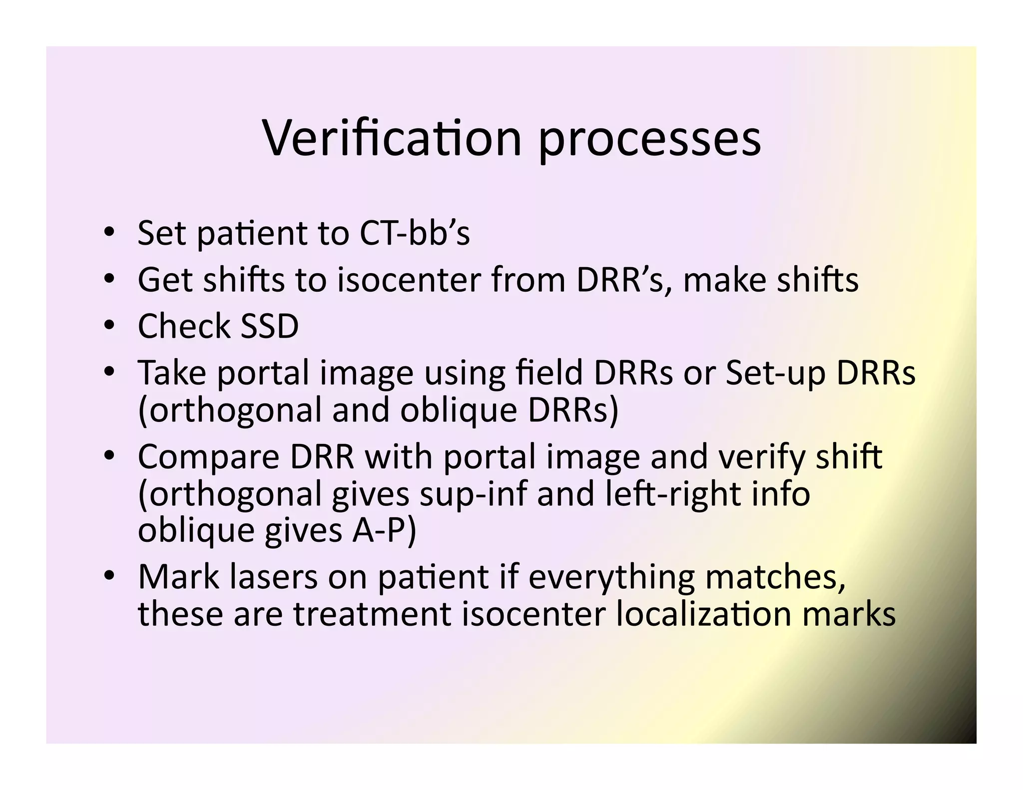


This document summarizes the process of simulation for radiation therapy treatment planning from CT imaging to treatment verification. It describes how patient positioning is done using lasers during CT scanning and how the CT images are imported into the treatment planning system. It also explains how the treatment planning system localizes CT markers and defines the isocenter in machine coordinates for treatment. Finally, it summarizes the verification process of aligning the patient using digital reconstructed radiographs and portal images to ensure accurate treatment delivery.