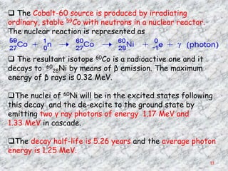
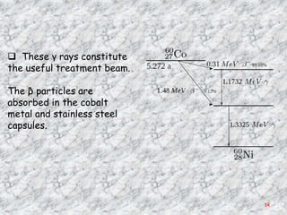
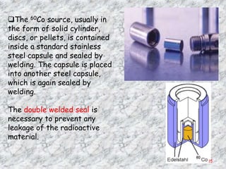
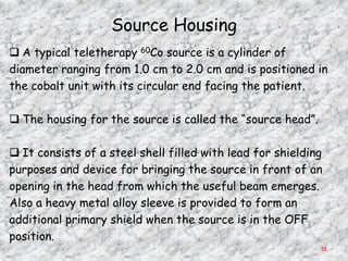
Downloaded 871 times
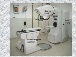
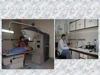
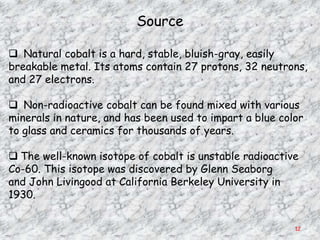
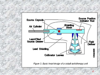
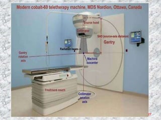


The document discusses isotopic teletherapy machines, which use cobalt-60 or cesium-137 radioactive sources to produce gamma rays for external beam radiation therapy. It describes the components and operation of cobalt-60 teletherapy machines, including the radioactive cobalt-60 source, source housing, collimators, gantry, patient support assembly, and control console. Key factors in selecting radioisotopes are high gamma ray energy, long half-life, and ability to produce large quantities for clinical use.


