Downloaded 5,333 times
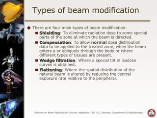
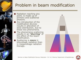
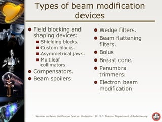
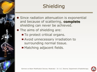
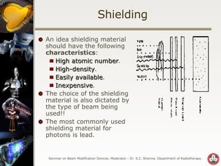
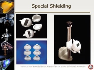

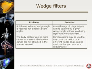
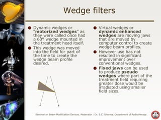
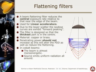

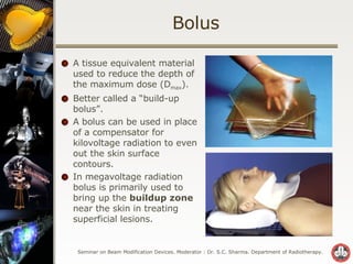


Beam modification devices are used in radiotherapy to modify the spatial distribution of radiation within the patient. The main types of beam modification are shielding to eliminate dose to some areas, compensation to allow for irregular surfaces and tissues, wedge filtration to modify isodose curves, and flattening filters to modify the natural beam profile. Beam modification devices can alter the dose distribution due to effects of primary radiation attenuation and scattering. Common beam modification devices include shielding blocks, compensators, wedges, and multileaf collimators.