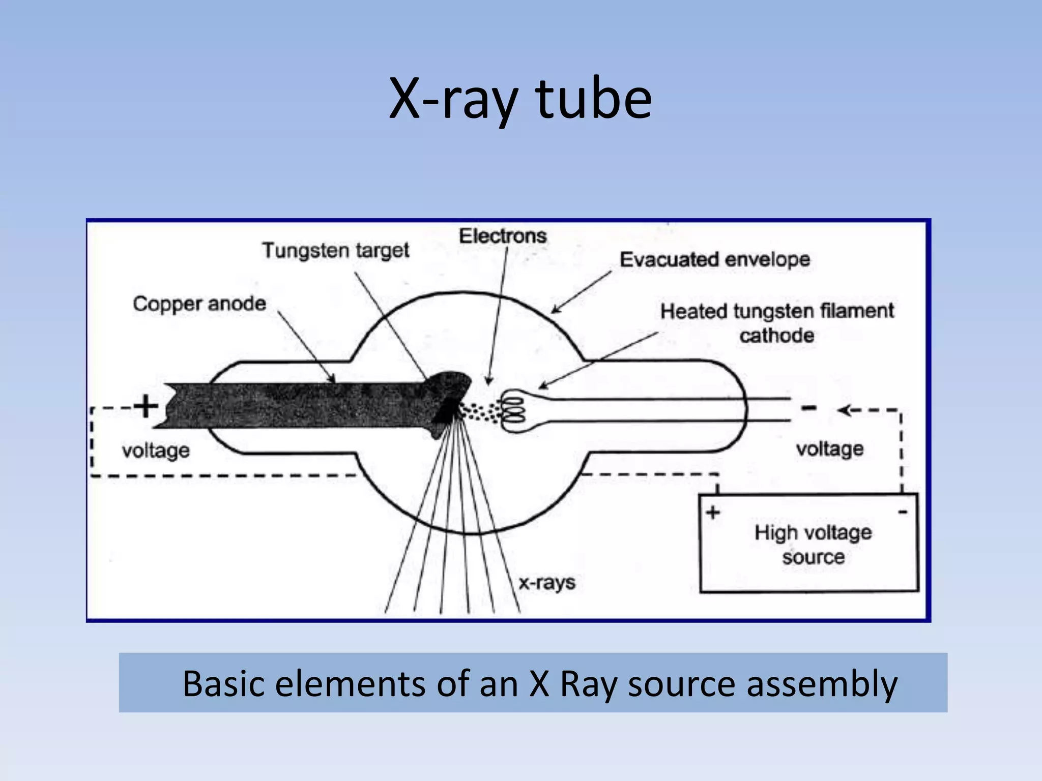
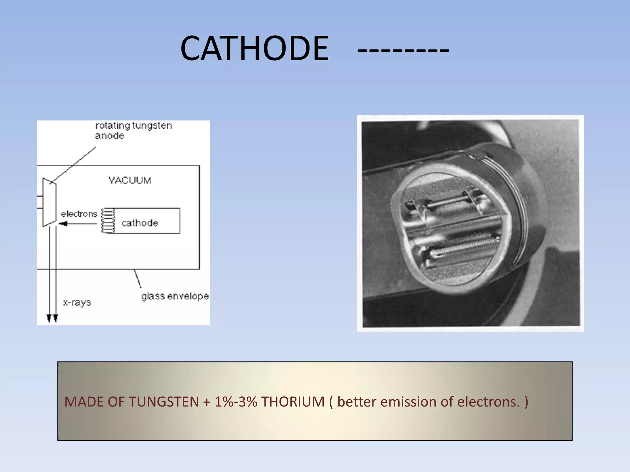
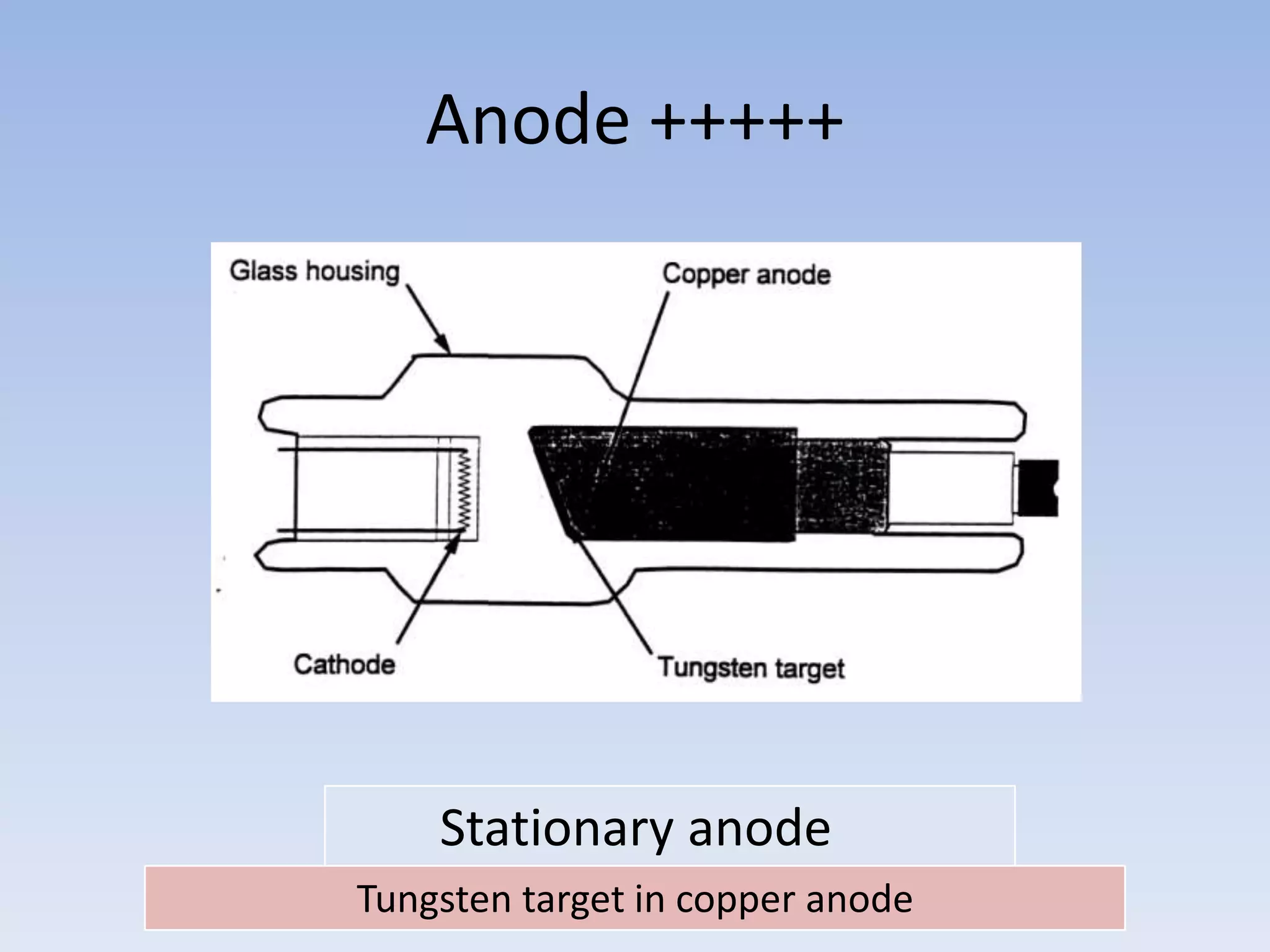
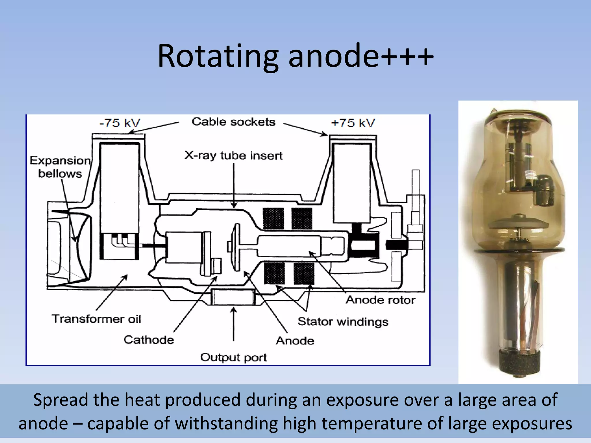
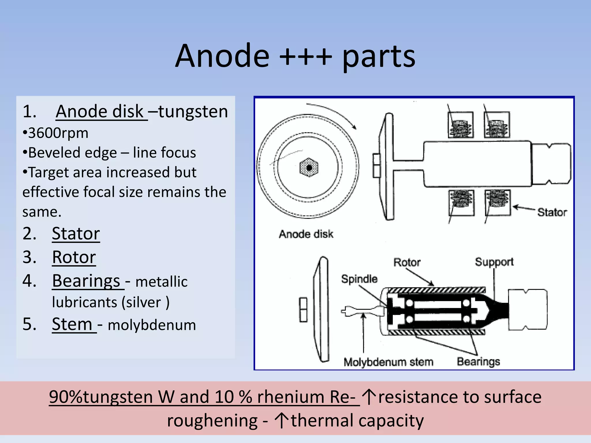
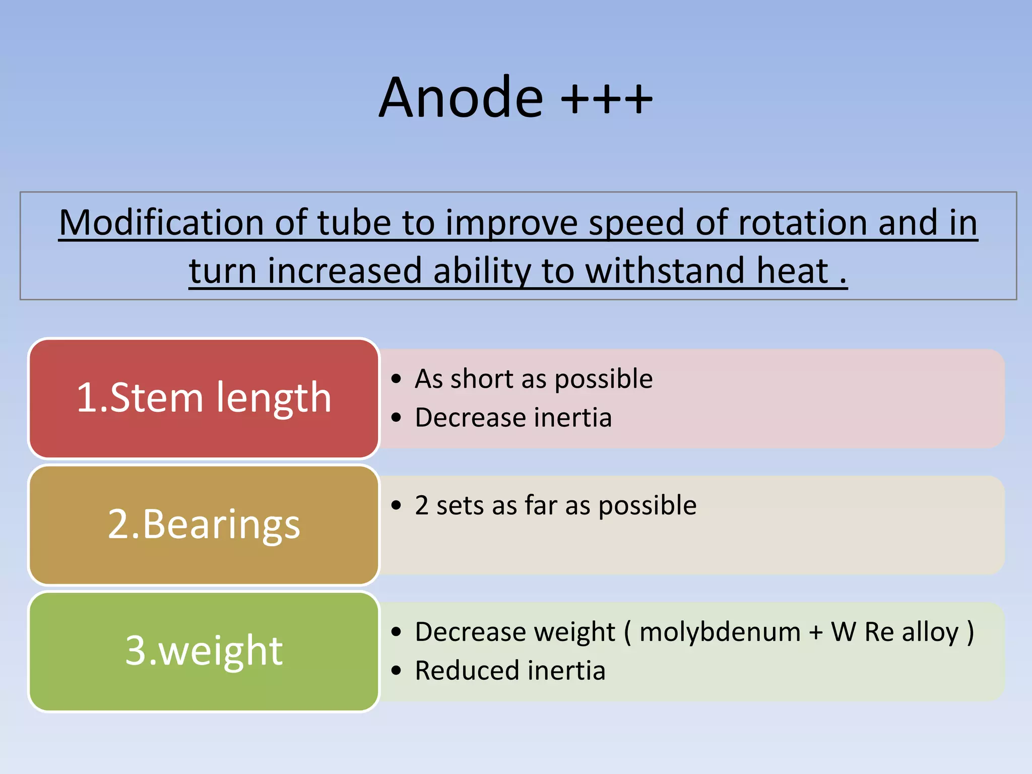
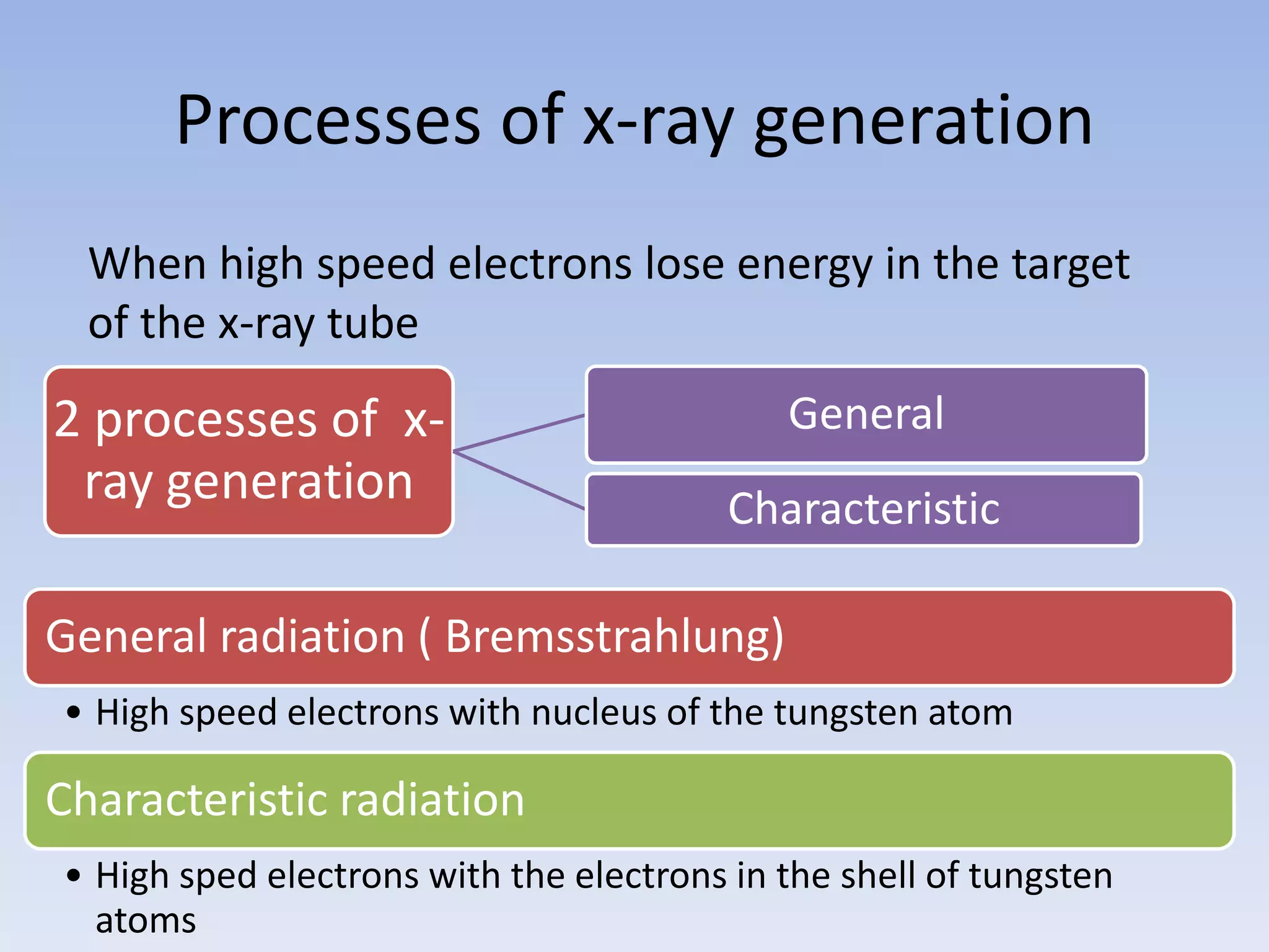
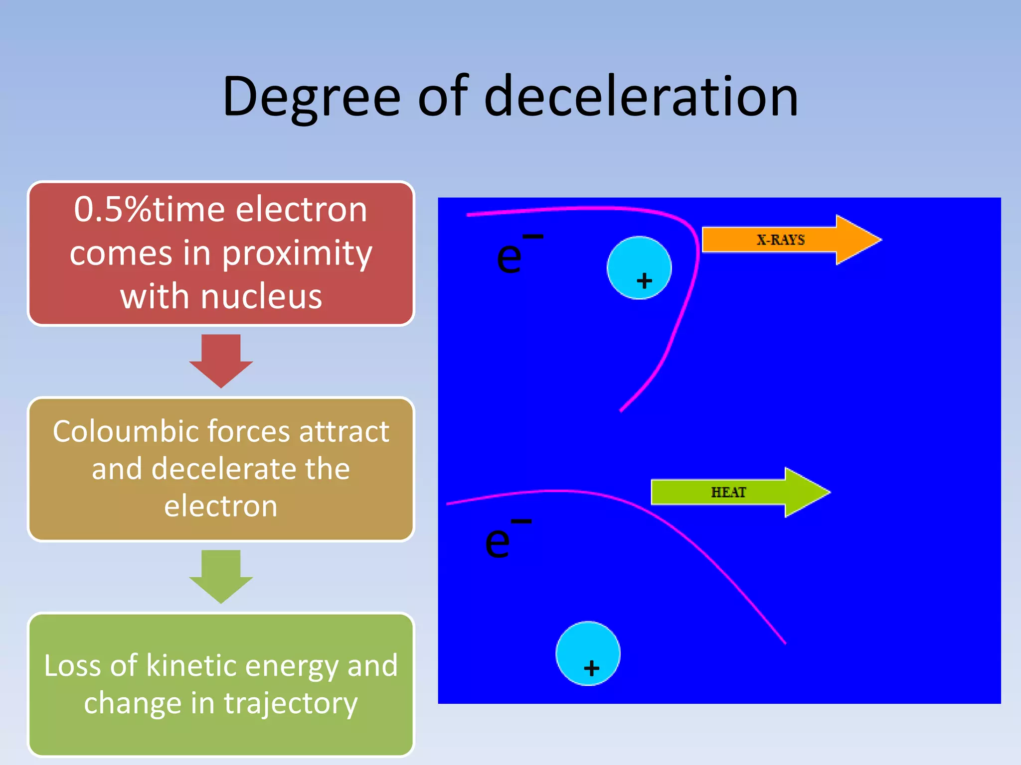
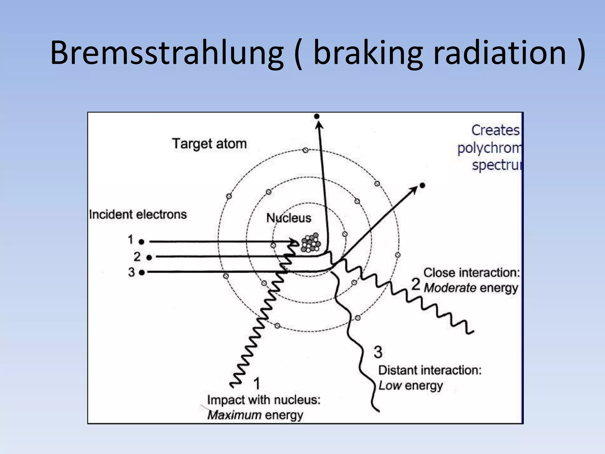
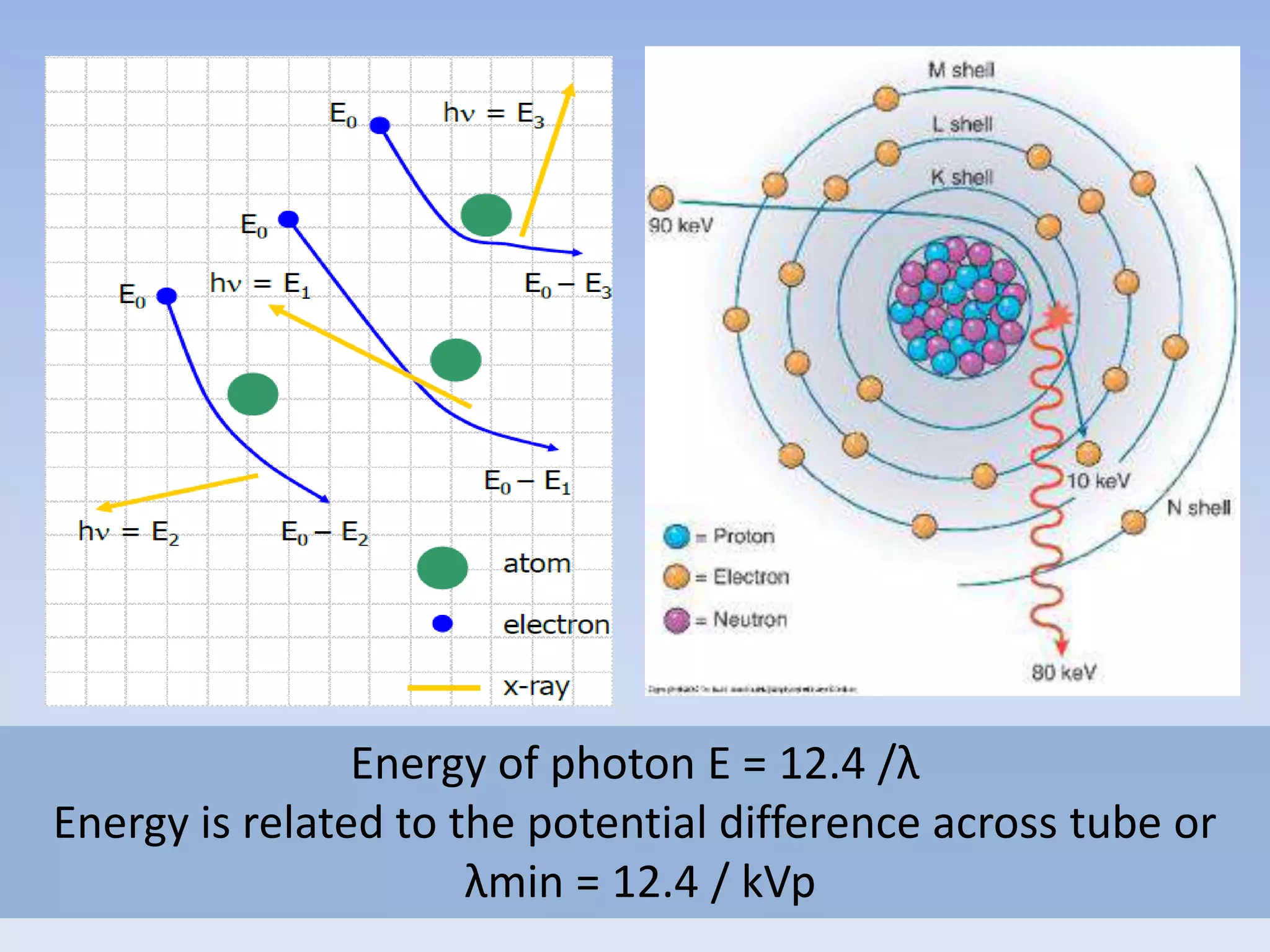
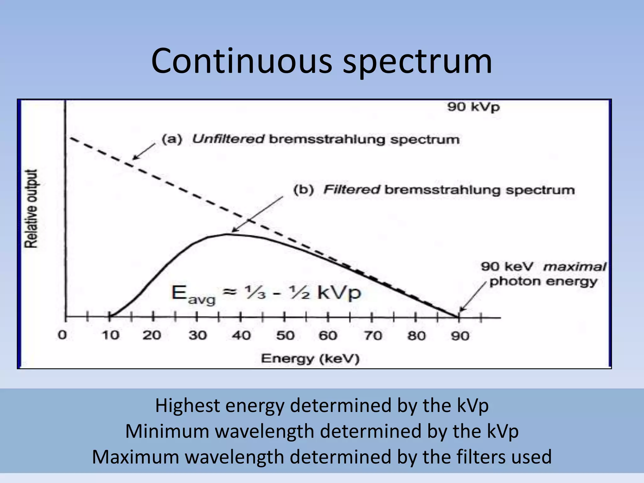
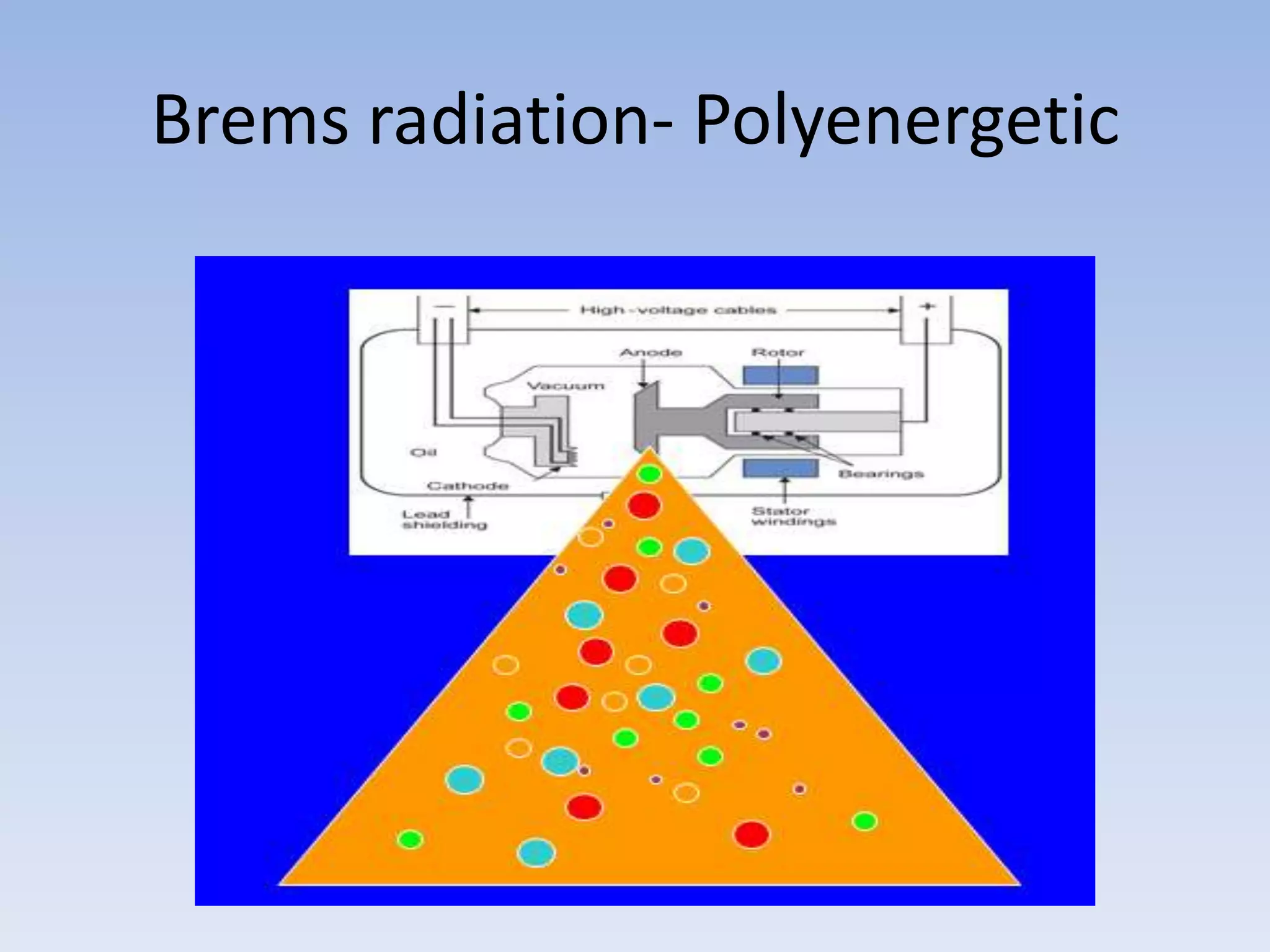
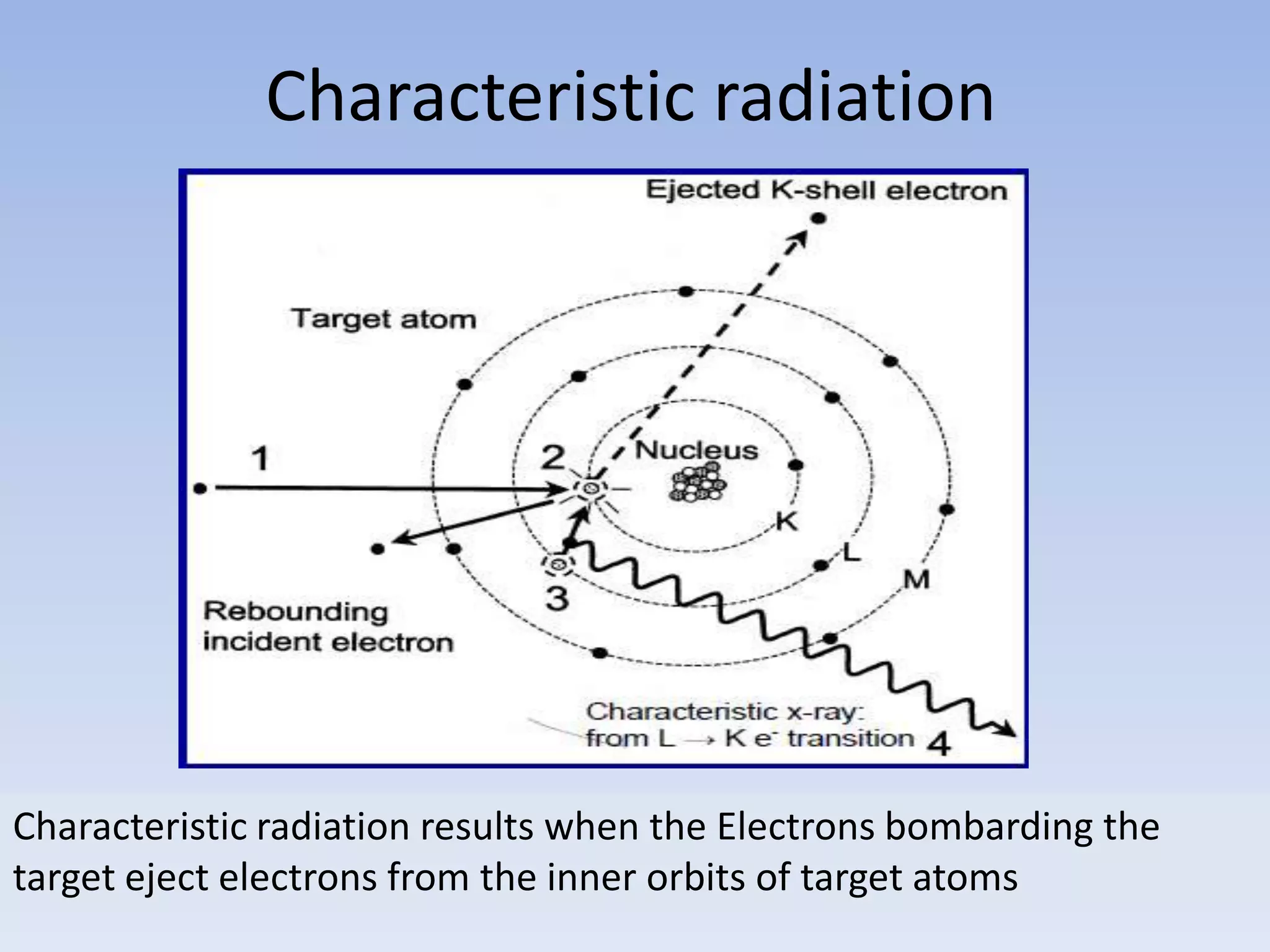
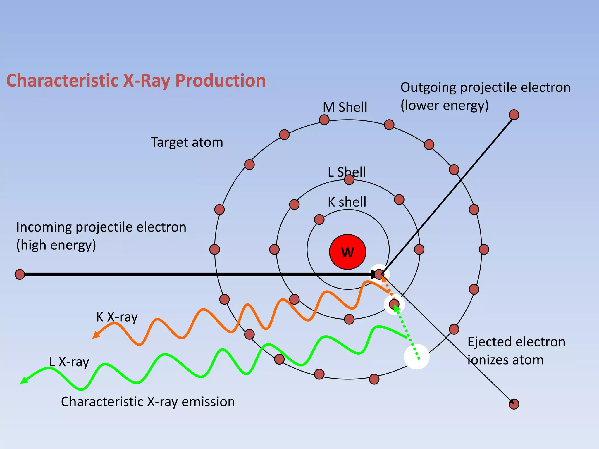
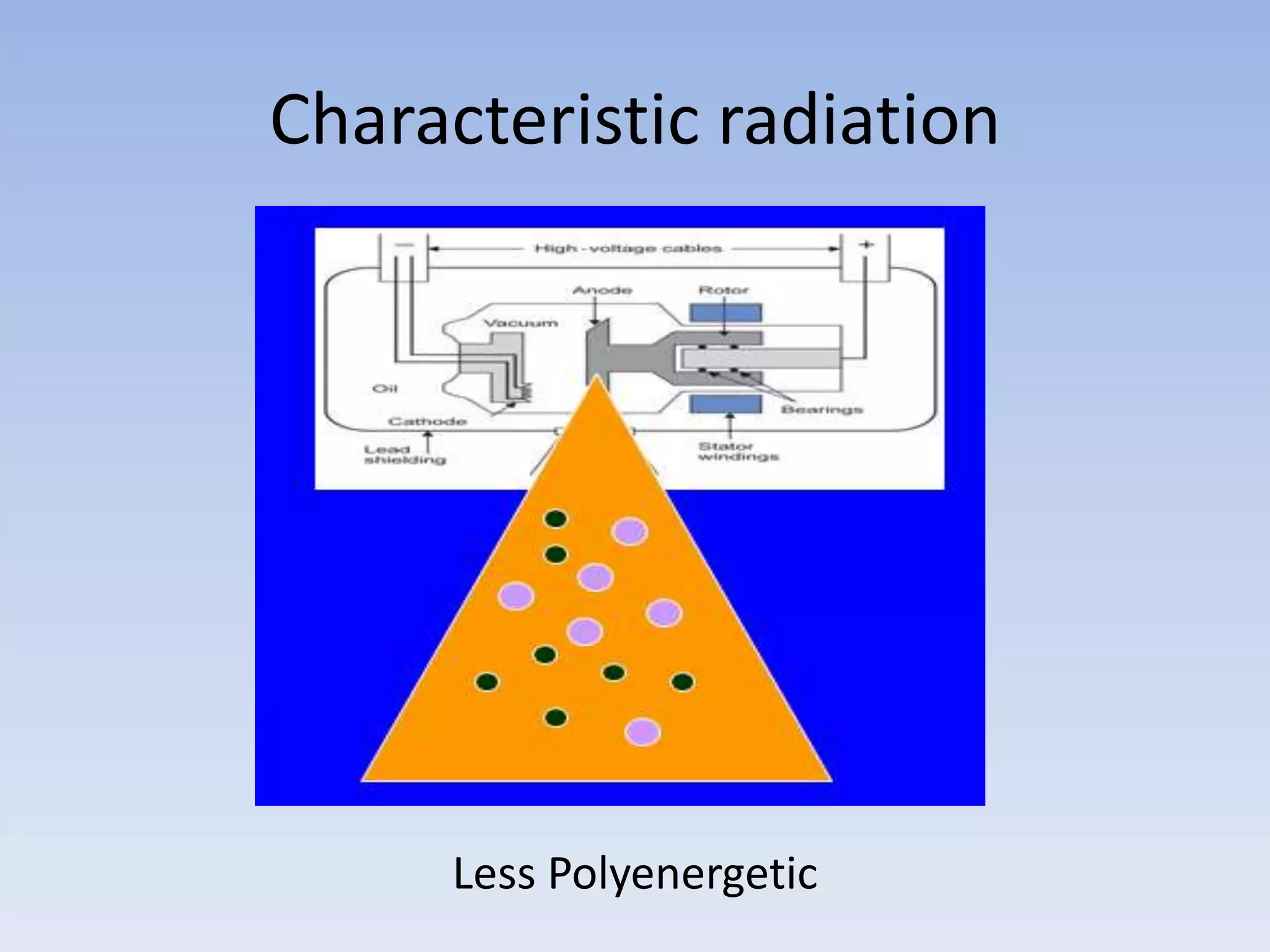
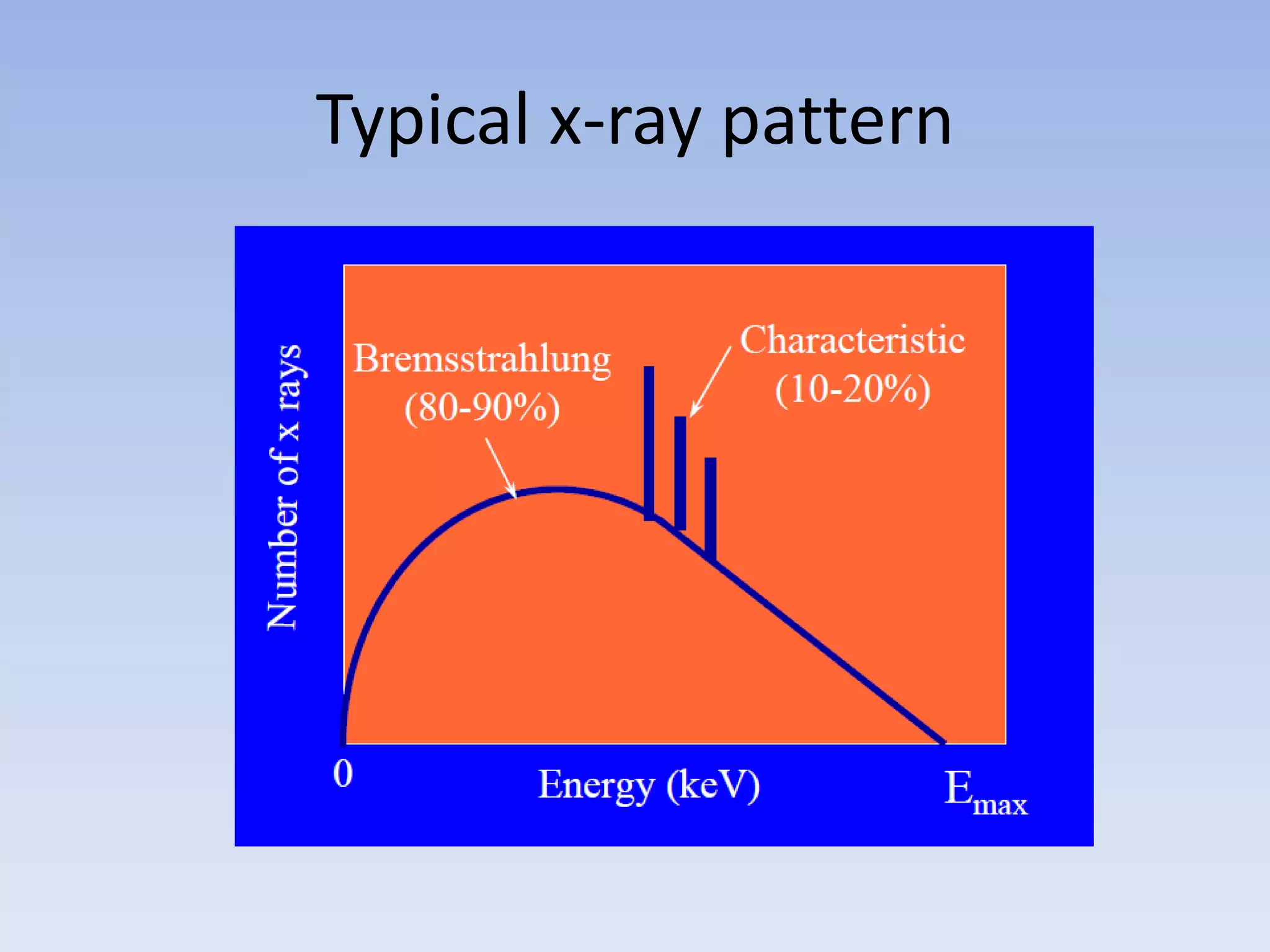
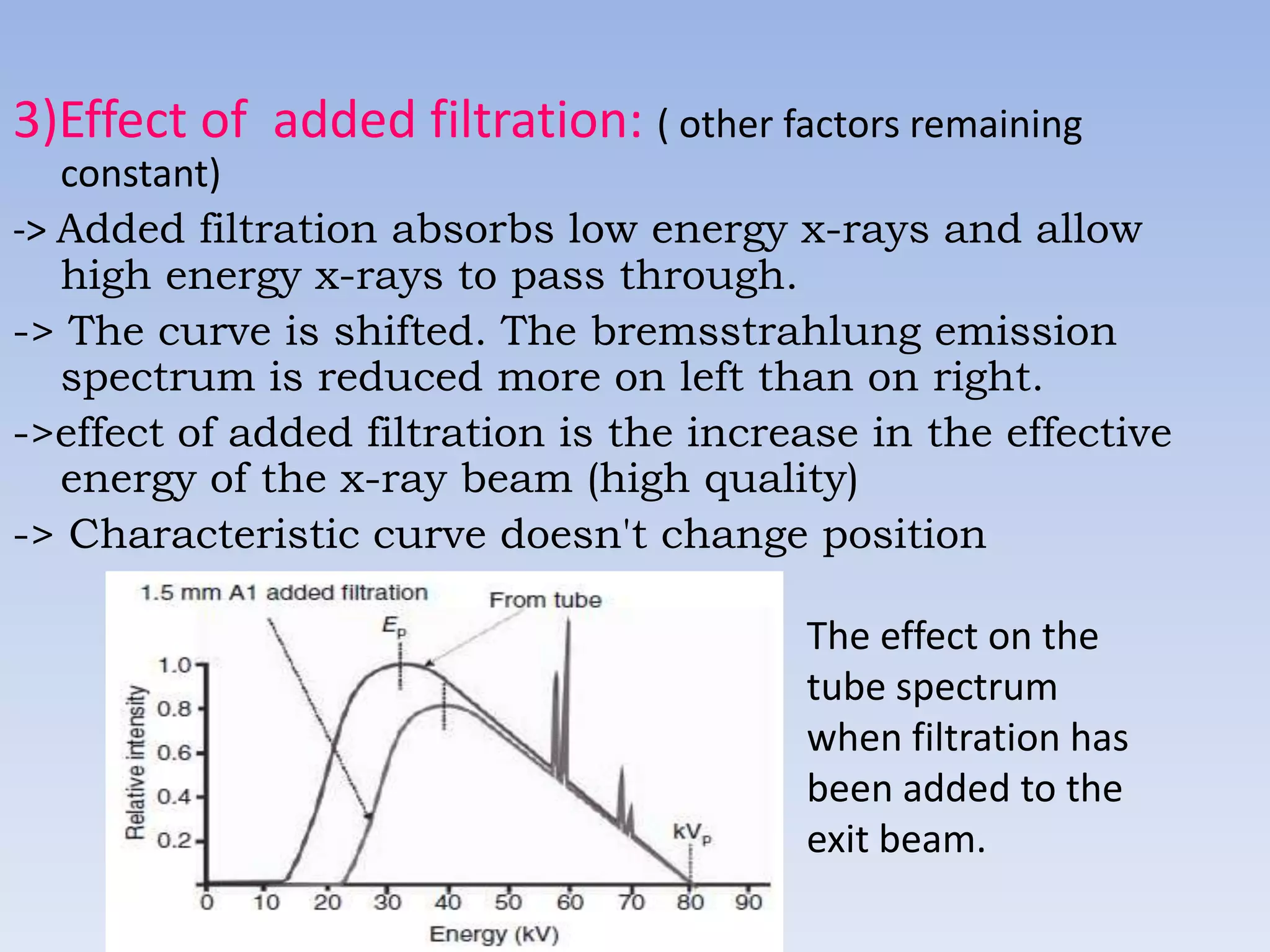
Electromagnetic radiation, including x-rays, is produced when electrons are accelerated and decelerate, such as when they collide with the target material in an x-ray tube. In an x-ray tube, a stream of electrons is emitted from a heated cathode and accelerated toward the anode. When the electrons collide with the anode, they cause the emission of x-rays. This results in a spectrum of x-rays known as bremsstrahlung radiation. Some electrons may also eject inner shell electrons from the anode atoms, producing characteristic x-ray lines. Modern x-ray tubes use a rotating anode to dissipate heat and allow higher outputs.
The document discusses key concepts related to x-ray tube function including:
1. The line focus principle allows for a smaller effective focal spot size while maintaining a larger actual focal spot size, improving heat dissipation and image quality.
2. The anode heel effect results in decreased x-ray intensity on the anode side of the tube compared to the cathode side, due to greater absorption of x-rays that pass through more of the angled anode target.
3. Off-focus radiation is produced when electrons bombard areas of the target outside the focal spot, and techniques like using a diaphragm can help reduce such stray radiation.
This document discusses fluoroscopy and the components of a fluoroscopy system. It describes how fluoroscopy allows real-time visualization of organ motion, contrast agents, stent placement, and catheterization. It then provides details on the evolution of fluoroscopy technology over time, from early fluoroscopes to modern image intensifiers and closed-circuit television systems. Key components like the image intensifier tube, video camera, and television monitor are explained. Methods of image recording like spot film devices and video recording are also summarized.
X-ray generators use transformers, rectifiers, and capacitors to convert electrical power into high voltage pulses needed to generate x-rays. There are several types of x-ray generators including single phase generators that produce two pulses, three phase six pulse generators that use three phase power, and three phase twelve pulse generators that add an additional delta connection to produce twelve pulses. High frequency generators use high frequency current to provide a constant voltage to the x-ray tube. Power discharge generators include capacitor discharge generators that use a high voltage capacitor to store and discharge charge, and battery powered generators that use batteries as the power source.
This document discusses the interaction of ultrasound with matter. It explains that ultrasound reflections, refractions, absorptions, and scatterings are determined by the acoustic properties of tissues. Reflection is the most important interaction for generating ultrasound images. Reflection depends on the acoustic impedance at tissue interfaces, which is determined by density and sound velocity. Differences in acoustic impedance between tissues result in more reflection. Absorption converts ultrasound to heat as it passes through tissues. Scattering results in weaker, diffuse reflections that degrade image quality. Refraction bends ultrasound beams at tissue boundaries based on changes in sound speed. The effects of these interactions are important for ultrasound imaging.
The document provides a summary of conventional fluoroscopy and image intensifier technology. It discusses the key components of early fluoroscopes including fluorescent screens and image intensifier tubes. The development of more advanced image intensifiers is described, allowing for lower radiation doses, permanent image recording, and improved image quality through electronic imaging systems. Modern fluoroscopy systems use digital image processing and recording techniques to provide real-time visualization of internal structures during medical procedures.
MRI uses strong magnetic fields and radio waves to produce detailed images of the inside of the body. Protons in the body align with the magnetic field, and radio waves excite the protons causing them to emit signals. The signals are detected by coils and used to construct an image on a computer. Different tissues can be distinguished based on proton density and relaxation times after excitation. Gradient fields are used to localize the source of the signals within the body.
This document discusses various MRI sequences. It describes spin echo sequences, inversion recovery sequences, gradient echo sequences, and echo planar imaging. Free induction decay is discussed as a short-lived signal appearing after a 90 degree RF pulse that does not contribute to image formation. Parameters, modifications, and uses of different sequences are outlined.
X ray generators use a high voltage transformer and rectifier circuit to power an x-ray tube. The transformer steps up the voltage from around 100-200V from the generator to over 100,000V needed by the tube. A filament transformer separately supplies around 10V to heat the tube filament and cause electron emission. Controls select the voltage and exposure time. The transformer and rectifiers are immersed in oil for insulation given the high voltages involved. Rectification converts the AC output to DC to allow current flow in only one direction through the tube.
Beam hardening artifact occurs when an X-ray beam passes through multiple materials of varying densities within a scan volume. This causes the beam to become harder as lower energy photons are preferentially absorbed, leading to streaks or shading in the reconstructed CT image. Photon starvation is another cause of streak artifacts, occurring when there is insufficient photon flux passing through areas of higher attenuation, such as across the shoulders. Adaptive filtering and modulating tube current based on attenuation can help reduce these artifacts. Ring artifacts from defective detector elements in older CT scanners appear as rings in the reconstructed images.
Dr Pawan Kumar presented on MRI principles, techniques, and reading. MRI works by using a strong magnetic field to align proton spins in the body. Radiofrequency pulses excite the protons, causing them to emit signals as they relax back to equilibrium. These signals are used to form MRI images. Key hardware includes magnets, gradient coils, and RF coils. MRI contrast depends on tissue T1 and T2 relaxation times and the chosen TR and TE parameters. Different sequences like T1-weighted, T2-weighted, and FLAIR are used to highlight various tissues and pathologies. Contrast agents can also be used to improve tissue contrast on MRI scans.
Principle of usg imaging, construction of transducersDev Lakhera
This document discusses the principles of ultrasound imaging, including the construction of transducers and ultrasound controls. It covers topics such as the properties of sound waves, how sound propagates through different mediums, the components and workings of an ultrasound transducer, and how ultrasound images are displayed. It also describes various ultrasound imaging controls and their functions.
1. The document discusses the key components of an x-ray tube, including the filament, focusing cup, glass envelope, and tube housing.
2. The filament is made of tungsten wire and emits electrons through thermionic emission when heated. The focusing cup concentrates the electron beam.
3. The glass envelope encloses and evacuates the tube. It is made of borosilicate glass to withstand heat and maintain vacuum. The tube housing provides radiation shielding and insulation for the high voltages used.
The document discusses various radiographic exposure factors and how they influence the quantity and quality of x-radiation exposure to patients. It describes how factors like kVp, mA, and exposure time determine the radiation dose and beam quality. It also discusses how the design of the x-ray machine like focal spot size, filtration, and high voltage generation impact technical settings. Film factors like sensitometry, contrast, and processing also influence radiographic image quality.
Beam restricted device and filter used in x raySushilPattar
This document discusses various beam restricting devices and filters used in radiography to reduce radiation exposure. It describes common beam restricting devices like diaphragms, cones, cylinders and collimators which are used to limit the size of the primary x-ray beam and reduce scatter radiation. It also discusses different types of filters like inherent, aluminum, compound and molybdenum filters which absorb low energy photons and improve image quality. Maintaining proper collimation and use of appropriate filters helps achieve the ALARA principle of keeping radiation exposure As Low As Reasonably Achievable.
Wilhelm Conrad Röentgen was a German physicist who discovered x-rays in 1895. He was awarded the first Nobel Prize in Physics in 1901 for his discovery. Röentgen discovered x-rays accidentally while experimenting with cathode ray tubes. He noticed a fluorescent glow coming from a nearby screen and realized some new type of radiation was causing this. When he placed his wife's hand on photographic plates and exposed them to this radiation, the outline of bones in her hand appeared on the developed plate. This led him to name this new type of radiation "x-rays".
This document discusses the construction and types of x-ray films used in medical imaging. It begins with an overview of the layers that make up an x-ray film, including the adhesive layer, emulsion layer containing silver halide crystals, and protective supercoat layer. The document then discusses the history of film bases and characteristics of modern polyester bases. It describes the functions of duplitized and single emulsion films, advantages and disadvantages of each, and common film types and sizes used for different medical imaging purposes.
Viewing and recording the fluoroscopic imageSHASHI BHUSHAN
The document describes the process of viewing and recording intensified fluoroscopic images. It discusses how an image intensifier converts visual light images into electrical signals that are then viewed on a video monitor or recorded. Recording can be done using spot film cameras, cinefluoroscopy movie cameras, or by recording the video signal from the television camera onto magnetic tape, discs, or optical discs. The television camera converts the light image back into an electrical video signal for viewing, storage, or transmission to other viewing locations.
This document discusses the use of image quality indicators (IQIs), also known as penetrameters, in radiography. IQIs ensure a minimum level of sensitivity and image quality on radiography films. They are available in different styles and materials to match the part being inspected. Common IQI types include hole-type and wire IQIs. IQIs are selected based on codes or standards and placed on the part or a reference block to verify the radiography technique can detect discontinuities of a specified size, such as a 2% thickness change. IQIs help maintain consistent quality but do not guarantee all defects will be visible.
X- Ray physics- X-Ray Tube, Transformer, Generator and Rectifiers by kajalsra...DrKajalLimbad
X-Ray physics including x-ray tube, transformer, generator, and rectifiers. physics made an easy
Note: this ppt has many animations that may not be appreciated over here. Request original ppt at kajalsradiology@gmail.com
This document provides an overview of x-rays and x-ray tubes. It discusses the history of x-rays starting with their discovery by Wilhelm Roentgen in 1895. It then covers basic x-ray physics and the electromagnetic spectrum. The document focuses on the components and functioning of x-ray tubes, including the cathode, filament, focusing cup, anode, rotating target, and control console. It explains how varying the kVp and mAs settings on the control console controls the x-ray beam properties.
X-rays are produced when high-energy electrons collide with a metal target in an x-ray tube. Electrons are emitted from a heated cathode and accelerated toward the anode by a high voltage potential. Some electrons interact with atoms in the anode, producing x-ray photons. X-rays have different energies depending on the target material and voltage used. Additional filtration is often applied to produce clinically useful x-ray beams. Exposure factors like voltage, current, and time determine the quantity and quality of the emitted x-rays. X-rays are used to generate medical images by exploiting their ability to pass through and be absorbed by different tissues.
This document discusses factors that influence radiographic image quality. It describes three main types of contrast that make up image contrast: subject contrast, radiographic contrast, and subjective contrast. It also discusses factors influencing sharpness and techniques for improving sharpness such as minimizing object-film distance, immobilizing the patient, and using a high mA and short exposure time. Exposure factors like mAs, kVp, and focus-film distance are also covered in regards to their effects on density and contrast.
1. The document discusses the components of an x-ray generator, including a high tension generator and rectification system. It describes how alternating current is generated and then rectified to produce direct current needed to power the x-ray tube.
2. Key components are the step-up transformer, which increases voltage, the rectifier circuit, which converts AC to DC, and the step-down transformer to provide lower voltage for the filament.
3. The document explains different transformer types like autotransformer and the principles of electromagnetic induction that transformers use to change voltage levels in the x-ray circuit.
Interactions of X-ray & matter & Attenuation - Dr. Sayak DattaSayakDatta
Slideshow on Radio-physics covering different interactions between X-ray and matter along with Attenuation. It includes Photo-electric effect, Compton scatter, Coherent scatter, Attenuation of Monochromatic & Polychromatic radiation, Diagnostic Xray applications, Scatter radiations.
This document discusses grids used for scatter control in radiography. It begins with an introduction on grids, describing how they were invented and their purpose of removing scatter radiation. It then covers topics like grid construction, terminology, styles, evaluation methods and common positioning errors that can cause cutoff. Different grid patterns, focal ranges and selection criteria are outlined. While grids improve image contrast by reducing scatter, their use also increases patient dose and technical factors. The document provides an overview of grids and their role in controlling scatter in medical imaging.
Wilhelm Roentgen discovered X-rays in 1895 while experimenting with Crookes tubes. He called them "x-rays" as the nature of the radiation was unknown. The first X-ray photograph was of his wife Bertha's hand. X-rays are a form of electromagnetic radiation with much shorter wavelengths than visible light, in the range of 0.5-2.5 angstroms. They can be considered as both waves and particles called photons. X-rays are generated in an X-ray tube when high speed electrons interact with and lose kinetic energy in the target material, usually tungsten. This produces bremsstrahlung or braking radiation and characteristic radiation when electrons change energy levels within
Wilhelm Conrad Roentgen accidentally discovered x-rays in November 1895 while experimenting with cathode rays. He observed that a fluorescent screen near the tube glowed even when he placed objects between the tube and screen. When he placed his hand between the tube and screen, he could see the image of his bones. This established x-rays' ability to pass through objects and their use in medical imaging. Roentgen further studied x-rays' properties and named them x-rays since their nature was unknown. The first x-ray image ever taken was of Roentgen's wife Bertha's hand. X-rays are a form of electromagnetic radiation with wavelengths shorter than visible light. They can be described as either waves
X-rays are electromagnetic waves that are produced when fast moving electrons are stopped by a metal target. There are two main types of x-ray production: Bremstrahlung and characteristic radiation. Diagnostic x-rays are used to image bones and other dense tissues using the photoelectric effect. Filters and grids are used to improve image quality by reducing scattered radiation. Contrast media can also improve visibility of certain organs.
B.Tech sem I Engineering Physics U-IV Chapter 2-X-RaysAbhi Hirpara
This document discusses X-rays, including their discovery, production, properties, diffraction, absorption, and applications. X-rays were discovered in 1895 by Röntgen during experiments with cathode ray tubes. They are generated when high-speed electrons strike a metal target in an X-ray tube. X-rays have various wavelengths and are used in fields like medicine, science research, and industry for applications such as medical imaging, defect detection, and crystal structure analysis.
1. A current is passed through the tungsten filament to heat it up via thermionic emission and release electrons.
2. The electrons are accelerated towards the positively charged anode by the tube voltage and interact with the anode material, primarily releasing x-ray photons via Bremsstrahlung and characteristic interactions.
3. The resulting x-ray beam exits the tube and passes through the patient to form an x-ray image.
B.tech sem i engineering physics u iv chapter 2-x-raysRai University
This document provides an overview of X-rays, including their discovery, production, properties, diffraction, absorption, and applications. It discusses how X-rays are generated via the bombardment of a metal target by electrons in an X-ray tube. Key points covered include Bragg's law of diffraction, Moseley's law relating atomic number to X-ray wavelength, the continuous and characteristic spectra produced, and common medical and scientific uses of X-rays.
X ray generation Radiology information by rahul ppt 2Rahul Midha
X-rays are generated when high-energy electrons collide with a metal target in an X-ray tube. This produces both a continuous spectrum and characteristic peaks corresponding to the target material. Various techniques can be used to produce nearly monochromatic X-rays for diffraction experiments, including β filters to remove unwanted wavelengths, pulse-height discrimination with detectors, and diffraction from monochromator crystals which selectively pass the desired wavelength.
This document discusses various topics in radiation physics including:
- Atomic structure and the Bohr model of the atom.
- Composition and interactions of x-ray radiation.
- Components and function of x-ray machines including the cathode, anode, and power supply.
- Factors that control the x-ray beam such as milliamperage, kilovoltage, filtration, and collimation.
- Three main interactions of x-rays with matter: photoelectric absorption, Compton scattering, and coherent scattering.
- Key radiation physics concepts including exposure, absorbed dose, equivalent dose, and radioactivity.
X-ray Lab, Room 117 documents properties of x-rays including their electromagnetic nature, short wavelengths, and ability to be considered as both waves and particles. It describes how x-rays are produced via electron bombardment in an x-ray tube, and the continuous and characteristic spectra that result. Key safety aspects of x-ray sources like filtration, shielding, and interlocks are covered. Radiation safety depends on proper procedures to prevent accidental exposures from improperly configured equipment, equipment manipulation when energized, or failure to follow safety protocols.
X-rays are electromagnetic radiation that were discovered in 1895 by Wilhelm Roentgen. They are produced when electrons are accelerated and strike a metal target in an x-ray tube. There are two types of x-rays produced - bremsstrahlung x-rays and characteristic x-rays. Bremsstrahlung x-rays are produced when electrons are decelerated upon impact with the target nucleus. Characteristic x-rays are produced when an electron collision ejects an inner shell electron, causing an outer shell electron to fill the vacancy and release a photon. The x-ray tube contains a cathode, anode, and evacuated glass enclosure to precisely control the electron beam and produce x-rays, which have properties
This document provides information about x-rays and x-ray machines. It discusses the production of x-radiation through both braking radiation and characteristic radiation. The properties of x-rays include their physical properties like wavelength and speed of travel, as well as their ability to ionize atoms. The document also describes the components of an x-ray machine including the cathode, anode, collimator and transformers used to generate x-rays.
The document discusses the components and functioning of an x-ray tube. It describes the protective housing, cathode assembly made of thoriated tungsten, common anode materials like copper and molybdenum, and rotating versus stationary anodes. It also covers topics like the focal spot where electrons hit the anode, line-focus principle, heel effect, space charge effect, methods of heat transfer, voltage rectification, bremsstrahlung and characteristic radiation production, and how x-ray interaction varies with energy.
This document provides information on atomic structure and radiation physics. It discusses how atoms are made up of protons, neutrons, and electrons. The number of protons determines the atomic number and different elements have different numbers of protons. Radiation is emitted when high-speed electrons collide with atoms in an x-ray tube. This produces two types of x-rays: Bremsstrahlung and characteristic radiation. X-ray machines use high voltages and currents to accelerate electrons and produce x-rays, while transformers, filters and cooling systems manage the heat produced.
1) X-rays are a type of electromagnetic radiation produced when high-speed electrons interact with matter. They are commonly used in medicine for diagnostic imaging.
2) X-rays are produced via two main mechanisms when electrons interact with an target anode - bremsstrahlung and characteristic radiation. Bremsstrahlung occurs as electrons are decelerated and characteristic radiation occurs when electrons displace inner shell electrons.
3) X-ray tubes contain a cathode to emit electrons and a target anode to produce x-rays via interactions with electrons. Various components maintain the vacuum and shield unwanted radiation to deliver a useful x-ray beam for imaging.
This document provides an overview of x-ray production. It discusses how x-rays are produced through interactions between electrons and heavy atomic number targets. It describes the discovery of x-rays by Roentgen in 1895 and some key properties. The document then explains the basic processes of bremsstrahlung and characteristic x-ray production in more detail. It also discusses x-ray tube design components like the cathode, anode, vacuum, and housing needed to generate x-rays.
X-ray diffraction was discovered in 1895 by Wilhelm Röntgen. It involves using x-rays and analyzing the diffraction patterns formed after x-rays interact with the ordered structure of crystals. Bragg's law describes the conditions under which constructive interference of x-rays occurs leading to diffraction. X-ray diffraction is used to determine the atomic and molecular structure of crystals. It has applications in fields like materials science, chemistry, and structural biology.
Wilhelm Roentgen discovered X-rays in 1895 while experimenting with cathode ray tubes. He noticed fluorescent screens glowing in a darkened room when a high voltage was applied to the tube. This led to the discovery that X-rays could pass through and image bones in the human body. Modern X-ray tubes use a tungsten target bombarded by electrons emitted from a heated filament to produce X-rays, which are used in medical imaging and radiation therapy. X-rays are generated via two mechanisms: bremsstrahlung and characteristic radiation.
The document summarizes the production of X-rays. It describes that X-rays were discovered by Wilhelm Roentgen in 1895 while experimenting with electricity passing through glass. X-rays are produced when a stream of electrons is decelerated upon hitting a target anode in an X-ray tube. Key components of an X-ray tube include a glass enclosure, cathode, anode and housing, with vacuum used to prevent electron collision. X-rays are produced via two mechanisms: bremsstrahlung and characteristic radiation. Factors like target material, tube voltage and current affect X-ray production characteristics.
PRODUCTION AND PROPERTIES OF X.pptx BY MANOJ MANDAL(1).pptxManojMandal65
This document provides information about x-rays and the components responsible for their production. It discusses the history of x-ray discovery by Wilhelm Röntgen in 1895. It then describes the key components of an x-ray tube, including the cathode which emits electrons, and the anode which converts the electron energy into x-rays. The document explains how tungsten is commonly used for the filament and target due to its high melting point and ability to efficiently produce x-rays. It also discusses factors like focal spot size and line focus principle which allow controlling the size and shape of the x-ray beam.
Similar to Basics of radiation and production of x rays (20)
Thinking of getting a dog? Be aware that breeds like Pit Bulls, Rottweilers, and German Shepherds can be loyal and dangerous. Proper training and socialization are crucial to preventing aggressive behaviors. Ensure safety by understanding their needs and always supervising interactions. Stay safe, and enjoy your furry friends!
Executive Directors Chat Leveraging AI for Diversity, Equity, and InclusionTechSoup
Let’s explore the intersection of technology and equity in the final session of our DEI series. Discover how AI tools, like ChatGPT, can be used to support and enhance your nonprofit's DEI initiatives. Participants will gain insights into practical AI applications and get tips for leveraging technology to advance their DEI goals.
Macroeconomics- Movie Location
This will be used as part of your Personal Professional Portfolio once graded.
Objective:
Prepare a presentation or a paper using research, basic comparative analysis, data organization and application of economic information. You will make an informed assessment of an economic climate outside of the United States to accomplish an entertainment industry objective.
This presentation includes basic of PCOS their pathology and treatment and also Ayurveda correlation of PCOS and Ayurvedic line of treatment mentioned in classics.
বাংলাদেশের অর্থনৈতিক সমীক্ষা ২০২৪ [Bangladesh Economic Review 2024 Bangla.pdf] কম্পিউটার , ট্যাব ও স্মার্ট ফোন ভার্সন সহ সম্পূর্ণ বাংলা ই-বুক বা pdf বই " সুচিপত্র ...বুকমার্ক মেনু 🔖 ও হাইপার লিংক মেনু 📝👆 যুক্ত ..
আমাদের সবার জন্য খুব খুব গুরুত্বপূর্ণ একটি বই ..বিসিএস, ব্যাংক, ইউনিভার্সিটি ভর্তি ও যে কোন প্রতিযোগিতা মূলক পরীক্ষার জন্য এর খুব ইম্পরট্যান্ট একটি বিষয় ...তাছাড়া বাংলাদেশের সাম্প্রতিক যে কোন ডাটা বা তথ্য এই বইতে পাবেন ...
তাই একজন নাগরিক হিসাবে এই তথ্য গুলো আপনার জানা প্রয়োজন ...।
বিসিএস ও ব্যাংক এর লিখিত পরীক্ষা ...+এছাড়া মাধ্যমিক ও উচ্চমাধ্যমিকের স্টুডেন্টদের জন্য অনেক কাজে আসবে ...
How to Add Chatter in the odoo 17 ERP ModuleCeline George
In Odoo, the chatter is like a chat tool that helps you work together on records. You can leave notes and track things, making it easier to talk with your team and partners. Inside chatter, all communication history, activity, and changes will be displayed.
हिंदी वर्णमाला पीपीटी, hindi alphabet PPT presentation, hindi varnamala PPT, Hindi Varnamala pdf, हिंदी स्वर, हिंदी व्यंजन, sikhiye hindi varnmala, dr. mulla adam ali, hindi language and literature, hindi alphabet with drawing, hindi alphabet pdf, hindi varnamala for childrens, hindi language, hindi varnamala practice for kids, https://www.drmullaadamali.com
Assessment and Planning in Educational technology.pptxKavitha Krishnan
In an education system, it is understood that assessment is only for the students, but on the other hand, the Assessment of teachers is also an important aspect of the education system that ensures teachers are providing high-quality instruction to students. The assessment process can be used to provide feedback and support for professional development, to inform decisions about teacher retention or promotion, or to evaluate teacher effectiveness for accountability purposes.
A Strategic Approach: GenAI in EducationPeter Windle
Artificial Intelligence (AI) technologies such as Generative AI, Image Generators and Large Language Models have had a dramatic impact on teaching, learning and assessment over the past 18 months. The most immediate threat AI posed was to Academic Integrity with Higher Education Institutes (HEIs) focusing their efforts on combating the use of GenAI in assessment. Guidelines were developed for staff and students, policies put in place too. Innovative educators have forged paths in the use of Generative AI for teaching, learning and assessments leading to pockets of transformation springing up across HEIs, often with little or no top-down guidance, support or direction.
This Gasta posits a strategic approach to integrating AI into HEIs to prepare staff, students and the curriculum for an evolving world and workplace. We will highlight the advantages of working with these technologies beyond the realm of teaching, learning and assessment by considering prompt engineering skills, industry impact, curriculum changes, and the need for staff upskilling. In contrast, not engaging strategically with Generative AI poses risks, including falling behind peers, missed opportunities and failing to ensure our graduates remain employable. The rapid evolution of AI technologies necessitates a proactive and strategic approach if we are to remain relevant.
A review of the growth of the Israel Genealogy Research Association Database Collection for the last 12 months. Our collection is now passed the 3 million mark and still growing. See which archives have contributed the most. See the different types of records we have, and which years have had records added. You can also see what we have for the future.
it describes the bony anatomy including the femoral head , acetabulum, labrum . also discusses the capsule , ligaments . muscle that act on the hip joint and the range of motion are outlined. factors affecting hip joint stability and weight transmission through the joint are summarized.
1. BASICS OF RADIATION AND
PRODUCTION OF X-RAYS
Presented byDr. Dinanath Chavan
First year PGT, Department of
Radiodiagnosis
SMCH.
ModeratorDr. Mrinal Dey
Professor, Department of
Radiodiagnosis
SMCH.
2. Radiation
• Radiation is energy that travels through space or matter.
• Two types of radiation used in diagnostic imaging are
1. electromagnetic (EM) and
2. particulate.
Electromagnetic Radiation
• EM radiation includes:
(a) gamma rays,
(b) x-rays,
(c) visible light,
(d) radiofrequency
3. EM RADIATION
• In this type, the energy is "packaged" in small units
known as photons or quanta.
• Visible light, radio waves, and x-rays are different
types of EM radiation.
• EM radiation has no mass, is unaffected by either
electrical or magnetic fields, and has a constant
speed in a given medium.
• EM radiation travels in straight lines; however, its
trajectory can be altered by interaction with matter.
• EM radiation is characterized by wavelength (λ),
frequency (v), and energy per photon (E)
4. Particulate Radiation
• The other general type of radiation consists of small
particles of matter moving through space at a very high
velocity.
• Particle radiation differs from electromagnetic radiation
in that the particles consist of matter and have mass.
• Particle radiation is generally not used as an imaging
radiation because of its low tissue penetration.
• ex. Electron, alfa particles.
5.
6. Electromagnetic spectrum
X-rays are electromagnetic radiation of exactly the same nature
as light but of very much shorter wavelength
Unit of measurement in x-ray region is Å and nm.
1 Å = 10-10 m, 1 nm = 10 Å = 10-9 m
X-ray wavelengths are in the range 0.5 – 2.5 Å.
Wavelength of visible light ~ 3900 - 7500 Å.
7. Electromagnetic radiation is the transport of energy
through space as a combination of electric and magnetic
fields.
Electromagnetic ( EM ) radiation is produced by a
charge ( charged particle ) being accelerated .
{ electrons are consider as standing waves around the
nucleus and therefore do not represent acclerating
charges. }
Any accelerating charge not bound to atom will emit
EM radiation .
9. Electromagnetic radiation
According to the classical
theory Electromagnetic
radiation can be
considered as wave
motion .
According to the quantum
theory electromagnetic
radiation can also be
considered as a particles
called photons
10. Wave concept of electromagnetic radiation
•All EM radiations travel with the speed of light
186000miles/sec, 3×10ˆ8 m/sec but they differ in wavelength
•Wavelength (λ) – distance between 2 successive crests / trough
•Frequency (ν) – number of crests /cycle per second (Hz)
•
(λ) wavelength ↓ (ν) frequency ↑
•EM travel with the speed of light c , c=λν
•Wave concept of EMR explains why radiation may be reflected ,
refracted, diffracted and polarized .
If each wave has length λ and ν waves pass a given point in
unit time
velocity of wave is
v = λ× ν
11. Particle concept of electromagnetic radiation
•Short EM waves like XRAYS react with matter as if they are
particles rather than waves.
•These particles are discrete bundles of energy and each bundle is
called quantum /photon.
•Photon travel at the speed of light.
•Amount of energy carried by each photon depends on frequency
of radiation.
•If frequency doubled energy doubled .
•Particle concept can explain the interaction with matter like
photoelectric and Compton effect .
Energy calculated E=hν
h= Planck's constant (4.13×10 ˆ-18 Kev sec )
12. Relationship between wavelength and
energy
Relationship between wavelength and frequency
ν= c/λ
c – velocity of light (~3×10⁸ m/s)
also E= hν
Instead of ν
E =hc/λ ( h×c = 12.4)
E= 12.4/λ
•Energy of photon =ev
•X-ray measured in kilo ev , 1Kev = 1000 ev
14. Wilhelm Conrad Roentgen (18451923)
X-rays were first discovered in 1895 by the
German physicist William Roentgen, when using a
Crookes tube
He called them ‘x’ rays, ‘x’ for ‘unknown’.
15. Site of discovery
Roentgen's lab where, on 8
November 1895, he noticed an
extraordinary glow while
investigating the behavior of
light outside a shrouded
cathode tube. To his
astonishment, he saw the
shadows of the bones of his
hand when held between the
tube and a fluorescent screen.
Within two months he had
published a carefully reasoned
description of his work and the
famous radiograph of his wife's
hand.
18. Glass enclosure
•Vacuum: to control the
number and speed of the
accelerated electrons
independently.
• Pyrex glass is used.
19. Cathode -------•Negative terminal of
the x-ray tube is called
cathode or filament.
•Along with filament 2
other elements :
connecting wires and
focusing cup
Filament made of tungsten wire 0.2 mm diameter coiled to
form a vertical spiral 0.2 cm diameter and 1 cm length
21. Filament and focusing cup
( Nickel )
•
Modern tubes have two
filaments
1. Long One : higher
current/lower
resolution, larger
exposure
2. Short One : lower
current/higher
resolution.
Focusing cup maintained
At one point only one at same negative potential
is used
as the filament .
22. Focusing Cup
Cathode assembly of a dual-focus x-ray
tube. The small filament provides a
smaller focal spot and a radiograph with
greater detail, provided that the patient
does not move. The larger filament is
used for high-intensity exposures of short
duration.
1: long tungsten filament
2 : short tungsten filament
3 : real size cathode
23. Focusing cup
Current across
tube one direction
only
Mutual repulsion
↑Number of
electrons
Prevented by focusing cup – forces the
electron stream to converge on the anode
in required shape and size
Electron stream
spread out
Bombarding
Large area of
anode
24. Thermionic emission
When Current flows – wire heated
Absorbs thermal energy – electrons move a small
distance from the surface of metal
This escape is referred to as thermionic
emission
25. Thermionic emission
Emission of electrons resulting from the absorption of
thermal energy – thermionic emission
(Tungeston heated >22000C)
Electron cloud surrounding the filament produced by
thermionic emission is termed “Edison effect”
26. Space charge
•Collection of negatively charged electrons in the vicinity
of filament when no voltage applied btw cathode and
anode – space charge
•Number of electrons in space charge remain constant
•Tendency of space charge to limit the emission of more
electrons from the filament is called space charge effect
Filament current →filament temperature →rate of
thermionic emission
27. Space charge cloud
Temperature limited
Space charge cloud shield the electric field for tube voltages of 40kvp
and less ( space charge limited ) , above 40kvp space charge cloud is
overcome by voltage applied
29. Filament vaporization
•Filament vaporization – shorten the life
•Not heated for too long- filament boosting circuit
•Vaporized filament usually deposited on the inner
surface of glass wall
•Color deepens as the tube ages- bronze colored
“sunburn”
•Tends to increase filtration and changes the
quality of beam
31. Rotating anode+++
Spread the heat produced during an exposure over a large area of
anode – capable of withstanding high temperature of large exposures
32. Anode +++ parts
1. Anode disk –tungsten
•3600rpm
•Beveled edge – line focus
•Target area increased but
effective focal size remains the
same.
2. Stator
3. Rotor
4. Bearings - metallic
lubricants (silver )
5. Stem - molybdenum
90%tungsten W and 10 % rhenium Re- ↑resistance to surface
roughening - ↑thermal capacity
33. Anode +++
Modification of tube to improve speed of rotation and in
turn increased ability to withstand heat .
1.Stem length
2.Bearings
3.weight
• As short as possible
• Decrease inertia
• 2 sets as far as possible
• Decrease weight ( molybdenum + W Re alloy )
• Reduced inertia
34. Focal spot
•True focal spot :Area of the tungsten target (anode)
that is bombarded by electrons from the cathode.
•The size and shape of focal spot is determined by the
size and shape of the electron stream which hits the
target.
•Heat uniformly distributed on focal spot
35. Line focus principle
•Anode angle : defined as
the angle of the target
surface with respect to the
central ray in the x-ray field.
•Anode angle range :6°- 20°
•Line focus principle Effective focal spot size is
the length and width of the
focal spot projected down
the central ray in the x-ray
field .
38. Anode angle
Large focal spot = greater heat loading.
Small focal spot = good radiographic detail.
39. Heel effect
The heel effect: The heel
effect is due to a portion
of the x-ray beam being
absorbed by the anode.
This results in an x-ray
beam that is less
intense on the anode
side and more intense
on the cathode side. The
heel effect is more
pronounced with
steeper anode angles.
40. Heel effect
Intensity of exposure on
anode side < cathode side
of tube
Heel effect less noticeable
with large focus-film
distance
Heel effect is less with
smaller films
Cathode
←Intensity→
Anode
41. • The intensity of the x-rays emitted through the heel of
the target is reduced because they have a longer path to
travel in the target. The diff in intensity is as much as
45%
Factors affecting the heel effect:
1. Anode angle: the steeper the target → ↑↑ heel effect.
2. FFD: ↑↑ FFD → ↓↓ heel effect "with fixed film size".
3. Film size: ↓↓ film size → ↓↓ heel effect "with fixed FFD".
4. Roughening of the target surface → ↓↓ X-rays output & ↑↑
the heel effect.
• In radiographs of body parts of different thicknesses →
the thicker parts should be placed toward the cathode
(filament) side of the x-ray tube.
• e.g. AP film of the thoracic spine → anode end over the
upper thoracic spine where the body is less thick & the
cathode end of the tube is over the lower thoracic spine
where thicker body structures will receive the increased
exposure.
42. Properties of xrays
1.
2.
3.
4.
X-rays travel in straight lines.
X-rays are electrically neutral
X-rays are Polyenergetic and heterogeneous
X-rays travel at the speed of light electromagnetic radiation
5. X-rays are highly penetrating , invisible rays.
43. Properties of x-rays
6. X-rays cannot be deflected by electric field or
magnetic field.
7. X-rays cannot be focused by lens.
8. Photographic film is blackened by X-rays.
9. Fluorescent materials glow when X-rays are directed
at them.
10. Produce chemical and biologic changes by ionization
and excitation.
11. Liberate minute amounts of energies while passing
through matter.
12. X-rays interact with matter produce photoelectric
and Compton effect.
44. Processes of x-ray generation
When high speed electrons lose energy in the target
of the x-ray tube
2 processes of xray generation
General
Characteristic
General radiation ( Bremsstrahlung)
• High speed electrons with nucleus of the tungsten atom
Characteristic radiation
• High sped electrons with the electrons in the shell of tungsten
atoms
45. Degree of deceleration
0.5%time electron
comes in proximity
with nucleus
Coloumbic forces attract
and decelerate the
electron
Loss of kinetic energy and
change in trajectory
e‾
+
e‾
+
47. Enrgy of photon = enrgy of
initial ectron – enrgy of
braked electron
Energy of photon E = 12.4 /λ
Energy is related to the potential difference across tube or
λmin = 12.4 / kVp
48. Continuous spectrum
Highest energy determined by the kVp
Minimum wavelength determined by the kVp
Maximum wavelength determined by the filters used
51. Characteristic X-Ray Production
M Shell
Outgoing projectile electron
(lower energy)
Target atom
L Shell
K shell
Incoming projectile electron
(high energy)
W
K X-ray
L X-ray
Characteristic X-ray emission
Ejected electron
ionizes atom
53. Characteristic radiation
L
K
M
K
(β)70-2 = 68 keV
L
11-2 = 9 keV
M
(α)70-11= 59 keV
Between 80 and 150 kVp , k shell characteristic contributes to
about 10 %(80kVp) to 28%(150kVp) of useful beam.
54. Characteristic radiation
THERE ARE MANY
CHARACTERISTIC RADIATION
PRODUCED IN ONE ATOM
THEREFORE CHARACTERISTIC
RADIATION
IS ALSO POLYENERGETIC !
57. Factors affecting x- ray spectrum:1) Effect of tube current (mA) (while others
remain constant):
More mA more e- s flow from cathode to anode
Change in mA is directly proportional to the change
in the amplitude of the x-ray spectrum
Shape of the curve remain unchanged
The effect on the
tube spectrum when
the mA has been
halved.
58. 2)Effect of kV ( other factors remaining constant)
-> As kV is raised area under the curve increased
-> The position of the curve has been shifted to
the right to the high energy side
-> The increase is relatively greater for high
energy x-ray than for low energy x-ray
-> Characteristic curve doesn't change position
The effect on the tube
spectrum when the kV
has been reduced from
80 kV to 70 kV.
59. 3)Effect of added filtration: ( other factors remaining
constant)
-> Added filtration absorbs low energy x-rays and allow
high energy x-rays to pass through.
-> The curve is shifted. The bremsstrahlung emission
spectrum is reduced more on left than on right.
->effect of added filtration is the increase in the effective
energy of the x-ray beam (high quality)
-> Characteristic curve doesn't change position
The effect on the
tube spectrum
when filtration has
been added to the
exit beam.
60. Super Rolatix ceramic x-ray tube
Metal casing instead of glass envelope.
Three ceramic insulators – two insulators for the two high voltage
cables, and one supports the anode stem.
• Allows more compact tube design.
• Most common - Aluminium oxide.
Anode rotates on an axle which has bearings at each end – provides
greater stability and reduce the stress on shaft.
• Allows use of massive anode up to 2KG.
• larger heat storage capacity. Allows higher mAs settings.
61. Advantages of Metal -• less off focus Radiation .
• higher tube loading.
• longer tube life with high tube currents.
Cooling –
better cooling due to more efficient transfer of heat to the oil
through the metal enclosure, as compare to the glass
enclosure. ( metal is better conductor of heat )
Ν = nu ( initial for number in Greek ). Lambda = (λ)
Si unit for h = 6.62 ×10 ˆ-34 joules second ( J.s )
E in Kev and wavelength in A’. 1ev = amount of energy that an electron gains as it is accelerated by a potential difference of 1 V.
Connecting wires – supply both voltage and amperage to heat the filament
THORIUM increases the emission of electrons.
Xray current 100mA , 0.1 A1 ampere = rate of flow of 1 coulumb of electricity thro a conductor in 1 sec – 1 columb is 6.25 * 10^ 17
2200 degree temp for adequate amount of electron emission.
Space charge – prevent the electrons from being emitted from the filament until they have acquired sufficient thermal energy to overcome the force caused by space charge Loss of electrons – filament positive – attracts some electrons back – when filament heated to its emission temp ,state of equilibrium reached ,here number of electrons returning equal to number of electrons emitted
When potential difference is insufficient to cause almost all the elctrons to be pulled away from the filament the instant they are emitted – residual space charge Untill 40 kv the increse in kilovoltage produces a significant increase tube current evn thou filament heating remains same Above 40 kv however the increse in kv produce very little change in tube current In this example 40 kv is the saturation voltage Below 40 kv it is space charge limited Above 40 kv space charge effect no influence – tube current determined by the number of electrons made available by the eheated filament – temperature limited
X-ray circuit is turned on ,but no exposure is made ,a standby current heats the filament to a value corresponding to low current – for exposure, circuit will increase the filament current to required value and soon after exposure lower it standby value.
Tungsten target embedded in the large mass of copper Tungsten plate greater than 1 cm Tungsten atomic number 74 , high melting point Tungsten Good absorber and dissipater of heat Small target in larger copper – heat dissipation – even though high melting temp cannot withstand repeated exposures – cu better conductor of heat .so used for better conduction of heat and increased speed of cooling Tungsten larger than the focal size , as copper in the immediate vicinity can melt when the exposure increases the target temp by 1000. and cu doesn't have such high melting temperature 1070 oc .
At 3600 rpm , every 1/60thsec the target is opposite the electron beam . Rest of the time used for cooling typical disk diameter- 75,100,125mm Circumference = 2π r Stator coils –magnetic field produced by stator coils provide power for rotation Magnetic fields produced by stator induces a current in the rotor – provides power to rotate anode Bearings – anode assembly rotates on this Lubricants – earlier oil , graphite Stem – molybdenum( 2600) for heat dissipation , ↑length ↑inertia ↑load on bearings Inertia leads to delay 0.5 – 1 sec – safety circuit prevents exposure until rotor reaches full speed
Molybdenum disc with tungsten rhenium alloy target attached to it Weight of anode itself
The size ands shape of focsal spot can be determined by the size and shape of elctron stream Size and shape of ecltron stream – by dimension of filament tungsten wire coil , focusing cup , position of filament from focusing cup Focal spot is the area of anode bombarded by electrons from cathode – most energy converted into heat Heat uniformly distributed on over the focal spot – large amount of heat accumulated on the on anode – melting point of anode tungsten is 3370 – Large focal spot for greater heat loading Small focal spot for good radiographic detail
From where the xrays are emitted from the tube
Smaller anode angle will produce smaller focal spot and smaller field coverage
Intensity of x-ray beam is not uniformly distributed thro all portions of beam. decreased intensity at the anode side of tube as absorption by the target itself
Ffd – focus film distance
99% produce heat Electron attracted by the positive nucleus gets deflected from the original direction – electron loses energy and slowed down when its direction changes.Xray photon energy equal to the loss of kinetic energy
German
Initial elctron – deflected electron
Binding energy E for k shell of tungsten is 70 kevCathode electron should have more than 70 kVp to eject k shell electron K shell electron ejected after impinging electron uses 70 kVp to eject it – remaining energy shared between initial and ejected electron – both these electrons leave the atom . Removal of electron makesthe atom to have positive charge – return to normal state by losing excess energy Now the atom is unstable – k shell electron is replaced by l shell- l shell more energy than k shell – gives up the excess energy in the form of single x-ray photon