Downloaded 408 times


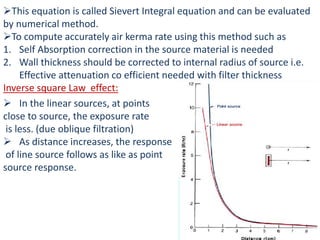


This document discusses brachytherapy dosimetry using the TG-43 formulation. It begins by introducing brachytherapy and the sources commonly used, such as iridium-192 and iodine-125. It then covers how sources are specified and calibrated, including using exposure rate constants, air kerma rate constants, and apparent activity. Methods for source calibration include air ionization chambers, well chambers, and solid phantoms. Dose distribution around sources is also discussed, including using the Sievert integral for line sources. The TG-43 formalism provides a standardized method for calculating dose around brachytherapy sources.


