Download as PDF, PPTX
![Purpose
To investigate dosimetric characteristics of a new linear accelerator designed
to deliver flattened, as well as flattening filter-free (FFF), beams. To evaluate the
accuracy of beam modeling under physical conditions.[4]
Francisco J. Hern´andez Flores (Arcispedale Santa Anna, Ferrara Italy)Radiation Therapy May 26, 2016 3 / 22](https://image.slidesharecdn.com/hospitalclassfff-160526195441/85/Flattening-filter-Free-3-320.jpg)
![Purpose
To investigate dosimetric characteristics of a new linear accelerator designed
to deliver flattened, as well as flattening filter-free (FFF), beams. To evaluate the
accuracy of beam modeling under physical conditions.[4]
To know the possible definitions and suggestions for some dosimetric
parameters for use in quality assurance of FFF beams generated by medical
linacs in radiation therapy.
Francisco J. Hern´andez Flores (Arcispedale Santa Anna, Ferrara Italy)Radiation Therapy May 26, 2016 3 / 22](https://image.slidesharecdn.com/hospitalclassfff-160526195441/85/Flattening-filter-Free-4-320.jpg)
![Purpose
To investigate dosimetric characteristics of a new linear accelerator designed
to deliver flattened, as well as flattening filter-free (FFF), beams. To evaluate the
accuracy of beam modeling under physical conditions.[4]
To know the possible definitions and suggestions for some dosimetric
parameters for use in quality assurance of FFF beams generated by medical
linacs in radiation therapy.
To compare the dosimetric accuracy of advanced dose calculation algorithms
for flattened (FF) and unflattened (FFF) photon beams.[5]
Francisco J. Hern´andez Flores (Arcispedale Santa Anna, Ferrara Italy)Radiation Therapy May 26, 2016 3 / 22](https://image.slidesharecdn.com/hospitalclassfff-160526195441/85/Flattening-filter-Free-5-320.jpg)
![Purpose
To investigate dosimetric characteristics of a new linear accelerator designed
to deliver flattened, as well as flattening filter-free (FFF), beams. To evaluate the
accuracy of beam modeling under physical conditions.[4]
To know the possible definitions and suggestions for some dosimetric
parameters for use in quality assurance of FFF beams generated by medical
linacs in radiation therapy.
To compare the dosimetric accuracy of advanced dose calculation algorithms
for flattened (FF) and unflattened (FFF) photon beams.[5]
We must to know the Dose calculation accuracy using Flattening filter free (FFF)
in Advanced treatment techniques, such as IMRT, VMAT and SBRT.
Francisco J. Hern´andez Flores (Arcispedale Santa Anna, Ferrara Italy)Radiation Therapy May 26, 2016 3 / 22](https://image.slidesharecdn.com/hospitalclassfff-160526195441/85/Flattening-filter-Free-6-320.jpg)
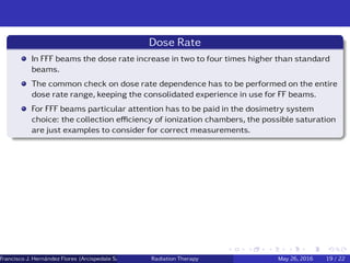
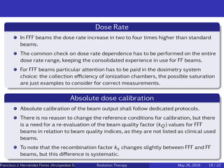
![Introduction
In recent years, the clinical use of flattening filter free (FFF) beams is growing fast.
Among the reasons, the very high dose rate achieved (up to four times the dose rate
of the standard flattened (FF) beams plays a decisive role.
This allowed for stereotactic radiotherapy deliveries of very high dose per fraction (as
20 to 25 Gy) in very short treatment times, comparable with the conventional fraction-
ation time slots.
FFF beams have been extensively investigated and characterized before their intro-
duction in the clinical practice.[1]
Francisco J. Hern´andez Flores (Arcispedale Santa Anna, Ferrara Italy)Radiation Therapy May 26, 2016 4 / 22](https://image.slidesharecdn.com/hospitalclassfff-160526195441/85/Flattening-filter-Free-7-320.jpg)
![Introduction
Flattening Filter
Conventional medical linear accelerators delivering photon beams are equipped
with a flattening filter (FF) in order to allow delivery of homogeneous dose
distributions with broad beams.
The differences between FFF and FF in terms of quality assurance is mainly
related to beam dosimetry, and not to mechanical characteristics of the linear
accelerator, for which the standard quality assurance procedures still hold.
Flattening Filter contribute to scattered, reduce dose rate, leakage from the
treatment head, beam hardening and also neutron fluence for high energy of X
ray used in Linac.[2]
Francisco J. Hern´andez Flores (Arcispedale Santa Anna, Ferrara Italy)Radiation Therapy May 26, 2016 5 / 22](https://image.slidesharecdn.com/hospitalclassfff-160526195441/85/Flattening-filter-Free-8-320.jpg)
![Flattening Filter free benefits
Increase the dose rate and reduce treatment time small treatment time less
patient movement.
Reduce leakage from the treatment head, they have 50% to 60% reduced
collimator and treatment head scatter.
reduced ”out of field” dose obserbed to be less than 10% at 2 cm for a 6MeV
beams FFF, up to 20% reduced neutron contamination for 18MeV Beams [2]
Francisco J. Hern´andez Flores (Arcispedale Santa Anna, Ferrara Italy)Radiation Therapy May 26, 2016 6 / 22](https://image.slidesharecdn.com/hospitalclassfff-160526195441/85/Flattening-filter-Free-9-320.jpg)
![Flattening Filter free benefits
Increase the dose rate and reduce treatment time small treatment time less
patient movement.
Reduce leakage from the treatment head, they have 50% to 60% reduced
collimator and treatment head scatter.
reduced ”out of field” dose obserbed to be less than 10% at 2 cm for a 6MeV
beams FFF, up to 20% reduced neutron contamination for 18MeV Beams [2]
Flattening Filter free Problem
Ion chamber and EPID saturation.
Inter leaf leakage, very high dose per pulse,
FFF can deposit dose of 1 Gy in 2.5 second inadvertent dose to critical
structures can be dangerous in extremely short time so therapist and patient
must be educated (24 Gy/min)
Francisco J. Hern´andez Flores (Arcispedale Santa Anna, Ferrara Italy)Radiation Therapy May 26, 2016 6 / 22](https://image.slidesharecdn.com/hospitalclassfff-160526195441/85/Flattening-filter-Free-10-320.jpg)
![Quality Assurance of FFF beams
Flattening Filter Free (FFF)
FFF beams are used in the linac without FF in place of carousel. FFF delivered with
conventional medical linear accelerator have the conical flattening filter removed and
replaced by a thin foil.[2]
This foil is introduced for two reason:
For safety. It will stop the electron beam reaching the patient if the target
collapses.
Producing enough signal in the ion chamber by producing electrons.[1]
The main advantages of removing the flattening filter are an increased dose
rate, reduced scatter, reduced leakage and reduced out-of-field doses.[1]
Francisco J. Hern´andez Flores (Arcispedale Santa Anna, Ferrara Italy)Radiation Therapy May 26, 2016 7 / 22](https://image.slidesharecdn.com/hospitalclassfff-160526195441/85/Flattening-filter-Free-11-320.jpg)
![Profile normalization
The inflection point
Ponisch et al [3] suggested the use of the inflection point at the field edge to
renormalize a FFF beam to the same dose level of a FF beam. From this
renormalized profile it is then possible to evaluate penumbra and the field size.
The correct evaluation of the inflection point position is critical, being located
by definition at the point of the highest dose gradient. [1]
The re-normalization value
The use of a renormalization factor, compared to the inflection point procedure,
allows for a location of the normalization point in a less critical position, at the
profile shoulder, where the FF and the corresponding FFF profiles start to differ,
and it is located at the second maximum point of the third derivative of the
profile.
Renorm Factor =
a + b ∗ FS + c ∗ depth
1 + d ∗ FS + e ∗ depth
(1)
Francisco J. Hern´andez Flores (Arcispedale Santa Anna, Ferrara Italy)Radiation Therapy May 26, 2016 9 / 22](https://image.slidesharecdn.com/hospitalclassfff-160526195441/85/Flattening-filter-Free-13-320.jpg)
![Profile normalization
Based on the fact that FFF beams deliver higher dose to the central axis, FFF and FF
beams should be mutually renormalized to superimpose the profile fall-off. Two meth-
ods can be followed: the inflection point or the renormalization value. Both methods
hold only for symmetric beams.
(a) Renormalization Point (b) Infection Point
Figure: Renormalization point obtained through the profile third derivative [1]
Francisco J. Hern´andez Flores (Arcispedale Santa Anna, Ferrara Italy)Radiation Therapy May 26, 2016 10 / 22](https://image.slidesharecdn.com/hospitalclassfff-160526195441/85/Flattening-filter-Free-14-320.jpg)
![Dosimetric field size
Once the FFF beams are renormalized as above, the concept of dosimetric field size
as the distance between the 50% dose levels can be used for FFF beams, as for FF
beams [generally the full width half maximum (FWHM) is used for standard FF beams
normalized to 100% at central beam axis].
Alternatively, as suggested by Pnisch et al.[3] the distance between the left and right
inflection points could be used
Francisco J. Hern´andez Flores (Arcispedale Santa Anna, Ferrara Italy)Radiation Therapy May 26, 2016 11 / 22](https://image.slidesharecdn.com/hospitalclassfff-160526195441/85/Flattening-filter-Free-15-320.jpg)
![Penumbra
For conventional flattened-beam profiles, the definition of the penumbra is based on
the 80-20% dose values. This is not applicable in the unflattened case. Therefore, the
penumbra of the unflattened profile were derived from the spatial distance between
the positions where the doses were 20 and 80 % of the normalized dose Dn
Dn =
Du
Df
∗ DCAX (2)
Figure: Normalization of an unflattened profile of a measured 6-MV photon
beam. [3]
Francisco J. Hern´andez Flores (Arcispedale Santa Anna, Ferrara Italy)Radiation Therapy May 26, 2016 12 / 22](https://image.slidesharecdn.com/hospitalclassfff-160526195441/85/Flattening-filter-Free-16-320.jpg)
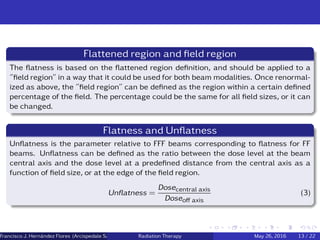
![Symmetry
Symmetry, as a parameter checking the equality level between left and right sides of a
profile, can be defined as usual for standard FF beams, with the only difference that the
evaluation area should be within the field region for FFF beams instead of the flattened
region commonly used in FF beams.[1]
The maximum dose ratio :
Dx
D−x max
(7)
The maximum Variation : (Dx − D−x)max (8)
where Dx and D−x are the doses at x and -x positions (symmetric relative to central
axis).
The area ratio :
LeftIntegral − RightIntegral
LeftIntegral + RightIntegral
(9)
where LeftIntegral and RightIntegral are the areas bounded by the profile on the left
and right of the beam central axis.
Francisco J. Hern´andez Flores (Arcispedale Santa Anna, Ferrara Italy)Radiation Therapy May 26, 2016 16 / 22](https://image.slidesharecdn.com/hospitalclassfff-160526195441/85/Flattening-filter-Free-20-320.jpg)
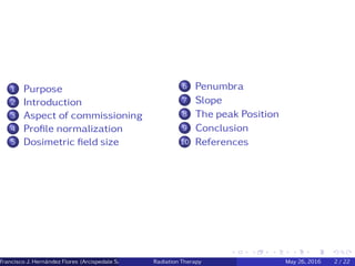
![Energy spectrum and quality index
FFF beams present an energy spectrum significantly different from FF beams
since the thick conical shaped attenuator is removed.[1]
Despite the differences in the FFF spectrum with respect to the corresponding FF
beam, there is no reason to change quality index definitions that can be.[1]
QI = 1.2661 ∗
D20cm
D10cm
− 0.0595. (10)
Francisco J. Hern´andez Flores (Arcispedale Santa Anna, Ferrara Italy)Radiation Therapy May 26, 2016 17 / 22](https://image.slidesharecdn.com/hospitalclassfff-160526195441/85/Flattening-filter-Free-21-320.jpg)
![Surface Dose
Due to different electron contamination and lower photon energy spectrum, surface
doses of FFF are expected to be different from FF beams.18 The surface dose param-
eter Ds is defined here as the relative dose at d = 0.5 mm with respect to the dose
at dmax.Due to different electron contamination and lower photon energy spectrum,
surface doses of FFF are expected to be different from FF beams. The surface dose
parameter Ds is defined here as the relative dose at d = 0.5 mm with respect to the
dose at dmax.[1]
Output Factor
The head scatter component of a FFF beam relative to the corresponding FF
beam is markedly different. Variation in output factors is then less pronounced
for FFF beams due to the head scatter component.[1]
Output factor definitions are kept identical for both FFF and FF beams.[1]
In both setup conditions the output factors of FFF fields are less spread, in
particular for in air evaluation, confirming the lower head scatter component for
such fields.[1]
Francisco J. Hern´andez Flores (Arcispedale Santa Anna, Ferrara Italy)Radiation Therapy May 26, 2016 18 / 22](https://image.slidesharecdn.com/hospitalclassfff-160526195441/85/Flattening-filter-Free-22-320.jpg)
![Conclusion
Removing the flattening filter improved the characteristics of the accelerator in terms
of smaller penumbras especially for the 18-MV mode, reduced MLC leakage, and less
variation in the total scatter factors.[3]
Although the FFF beams provide much high dose rate at the treatment target, the ion
recombination effect of the Farmer, PinPoint, and plane-parallel chamber in the FFF
photons is not significantly different from the flattened photons. These ion chambers
are suitable in the quality assurance and exposure measurement for the FFF beams
regarding their negligible ion recombination and sufficient collection efficiency.
We have presented ideas regarding the quality controls (QC) that have to be consid-
ered during the establishment of a quality assurance program (QA) when introducing
FFF beams into a clinical setting.
Francisco J. Hern´andez Flores (Arcispedale Santa Anna, Ferrara Italy)Radiation Therapy May 26, 2016 20 / 22](https://image.slidesharecdn.com/hospitalclassfff-160526195441/85/Flattening-filter-Free-25-320.jpg)


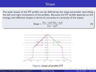
1. The document discusses commissioning parameters for flattening filter free (FFF) photon beams from a linear accelerator, including profile normalization methods, dosimetric field size, penumbra, and slope. 2. Profile normalization can be done using the inflection point or renormalization value to compare FFF and flattened beams. Dosimetric field size is measured as the 50% dose width. Penumbra is defined as the 20-80% distance for FFF beams after normalization. 3. Slope describes the peak shape of FFF profiles, and flatness/unflatness parameters are discussed to characterize beam homogeneity for both FFF and flattened beams.


![Arc therapy [autosaved] [autosaved]](https://cdn.slidesharecdn.com/ss_thumbnails/arctherapyautosavedautosaved-150423125828-conversion-gate01-thumbnail.jpg?width=640&height=640&fit=bounds)


