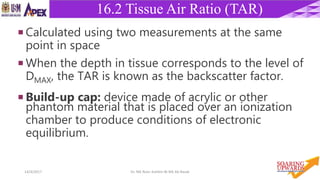
Downloaded 1,583 times


![5714/4/2017 Dr. Nik Noor Ashikin Bt Nik Ab Razak
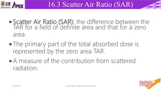
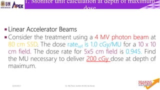
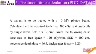
Practical Applications: example 2
Machine: 4 MV photons
Calibration conditions: SSD = 100 cm, dmax = 1 cm, field size = 10 10 cm.
Calibration dose rate = 1 cGy / MU
Treatment conditions: SSD = 120 cm, d = 10 cm, field size = 15 15 cm,
Sc(12.512.5)=1.010, Sp(1515)=1.010, %DD=66.7, TD = 200 cGy.
Dose/MU at prescription point
= 1 1.01 1.01 [(100+1)/(120+1)]2 0.667 = 0.474
MU = 200 / 0.474 = 422
SSD technique:](https://image.slidesharecdn.com/rtcalculation-170414022117/85/RADIOTHERAPY-CALCULATION-57-320.jpg)
![5914/4/2017 Dr. Nik Noor Ashikin Bt Nik Ab Razak
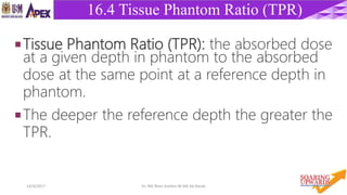
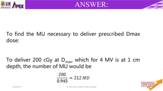
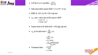
Practical Applications: example 4
SAD technique:
Machine: 4 MV photons
Calibration conditions: SCD = 101 cm, dmax = 1 cm, field size = 10 10 cm.
Calibration dose rate = 1 cGy / MU
Treatment conditions: SAD = 100 cm, d = 8 cm, field size = 6 6 cm,
Sc(66)=0.970, Sp(66)=0.990, TMR(8, 66)=0.787, TD = 200 cGy.
Dose/MU at prescription point
= 1 0.970 0.990 [(100+1)/(100)]2 0.787 = 0.771
MU = 200 / 0.771 = 259](https://image.slidesharecdn.com/rtcalculation-170414022117/85/RADIOTHERAPY-CALCULATION-59-320.jpg)
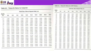
![6014/4/2017 Dr. Nik Noor Ashikin Bt Nik Ab Razak
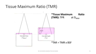
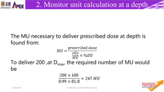
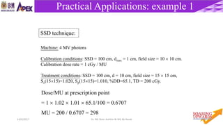
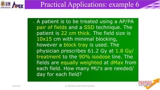
Practical Applications: example 5
Machine: Co-60 photons
Calibration conditions: SSD = 80 cm, dmax = 0.5 cm, field size = 10 10 cm.
Calibration dose rate = 130 cGy / min
Treatment conditions: SSD = 100 cm, d = 8 cm, field size = 15 15 cm,
Sc(1212)=1.012, Sp(1515)=1.014, %DD(8,15 15,100)=68.7, TD = 200 cGy.
Dose/MU at prescription point
= 130 1.012 1.014 [(80+0.5)/(100+0.5)]2 68.7/100 = 58.80
MU = 200 / 58.80 = 3.40 min
SSD technique:](https://image.slidesharecdn.com/rtcalculation-170414022117/85/RADIOTHERAPY-CALCULATION-60-320.jpg)

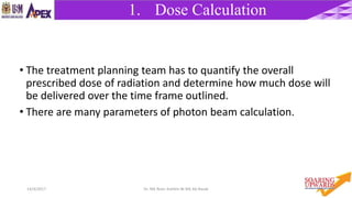
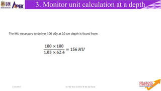
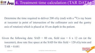
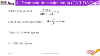
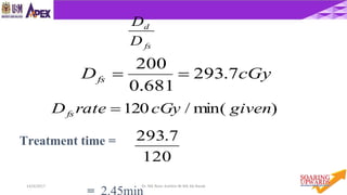
The document discusses various concepts and calculations related to photon dosimetry in radiotherapy. It defines key terms like monitor units, dose rate, depth dose, tissue maximum ratio and inverse square law. It explains the process of calculating treatment time, dose and monitor units for different setups using parameters like equivalent squares, percent depth dose, tissue air ratio and output factors. The calculations are described for both SSD and SAD treatment techniques.


