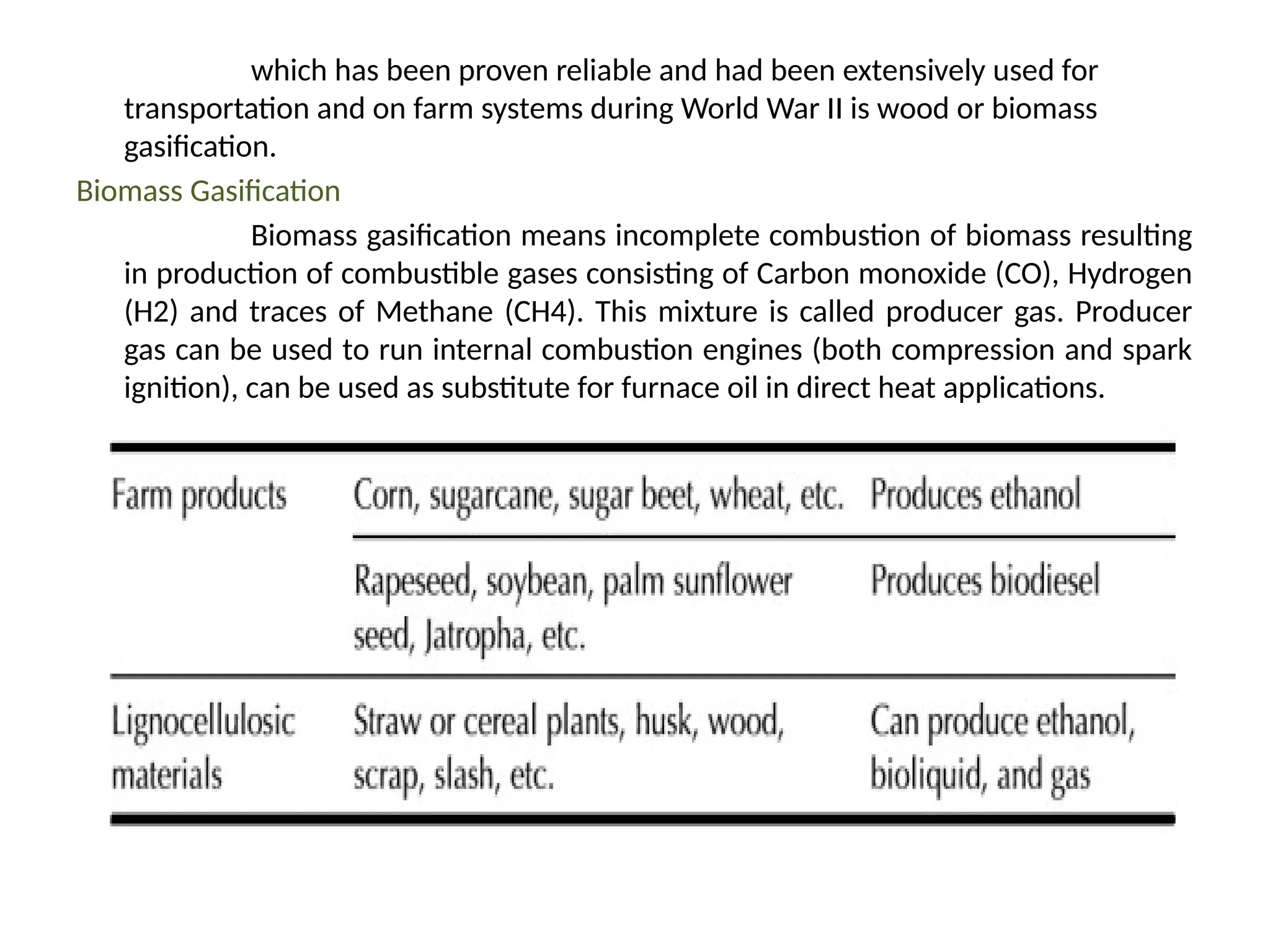
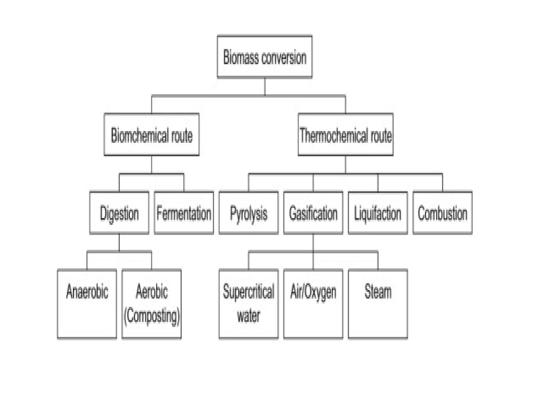
KONGUNADU COLLEGE OF ENGINEERING AND TECHNOLOGY
(AUTONOMOUS)
DEPARTMENT OF AGRICULTURAL ENGINEERING
Course: Biochemical and Thermo chemical
Conversion of Biomass
Topic : Thermo chemical conversion by
Gasification
By
Mr. M.Prabhu,
Assistant Professor,
Department of Agricultural Engineering,
Kongunadu College of Engineering and Technology
which has been proven reliable and had been extensively used for
transportation and on farm systems during World War II is wood or biomass
gasification.
Biomass Gasification
Biomass gasification means incomplete combustion of biomass resulting
in production of combustible gases consisting of Carbon monoxide (CO), Hydrogen
(H2) and traces of Methane (CH4). This mixture is called producer gas. Producer
gas can be used to run internal combustion engines (both compression and spark
ignition), can be used as substitute for furnace oil in direct heat applications.
Products of Biomass
Liquid fuels (ethanol, biodiesel, methanol, vegetable oil, and pyrolysis
oil). 2. Gaseous fuels (biogas (CH4, CO2), producer gas (CO, H2, CH4, CO2, H2),
syngas (CO, H2), substitute natural gas (CH4). 3. Solid fuels (charcoal, torrefied
biomass, biocoke, biochar).
These biomass products find use in following four major types of industries
• Chemical industries for production of methanol, fertilizer, synthetic fibre, and other
chemicals.
• Energy industries for generation of heat and electricity.
• Transportation industries for production of gasoline and diesel.
• Environmental industries for capture of CO2 and other pollutants.
Biomass Conversion
Bulkiness, low energy density, and inconvenient form of biomass are
major barriers to a rapid transition from fossil to biomass fuels. Unlike gas or
liquid, biomass cannot be handled, stored, or transported easily.
Chemistry Of Gasification
The production of generator gas (producer gas) called gasification, is
partial combustion of solid fuel (biomass) and takes place at temperatures of
about 10000
C. The reactor is called a gasifier.
The combustion products from complete combustion of biomass
generally contain nitrogen, water vapor, carbon dioxide and surplus of oxygen.
However, in gasification where there is a surplus of solid fuel (incomplete
combustion) the products of combustion are combustible gases like Carbon
monoxide (CO), Hydrogen (H2) and traces of Methane and no useful products like
tar and dust.
Production of thermal energy is the main driver for this conversion route that has five
broad pathways:
• Combustion
• Carbonization/torrefaction
• Pyrolysis
• Gasification
• Liquefaction
Combustion
Chemically, combustion is an exothermic reaction between oxygen and
hydrocarbon in biomass. Here, the biomass is oxidized into two major stable
compounds, H2O and CO2. The reaction heat released is presently the largest
source of human energy consumption, accounting for more than 90% of the
energy from biomass. Heat and electricity are two principal forms of energy
derived from biomass.
District or industrial heating is also produced by steam generated in
biomass-fired boilers.
Pyrolysis
Unlike combustion, pyrolysis takes place in the total absence of oxygen,
except in cases where partial combustion is allowed to provide the thermal energy
needed for this process. This process thermally decomposes biomass into gas,
liquid, and solid by rapidly heating biomass above 300-400o
C.
In pyrolysis, large hydrocarbon molecules of biomass are broken down
into smaller molecules. Fast pyrolysis produces mainly liquid fuel, known as bio-oil,
whereas slow pyrolysis produces some gas and solid charcoal
Torrefaction
Torrefaction is being considered for effective utilization of
biomass as a clean and convenient solid fuel. In this process, the biomass
is slowly heated to 200-300o
C without or little contact with oxygen.
Torrefaction alters the chemical structure of biomass hydrocarbon to
increase its carbon content while reducing its oxygen. Torrefaction also
increases the energy density of the biomass and makes the biomass
hygroscopic.
Gasification
Combustion zone
The combustible substance of a solid fuel is usually composed of
elements carbon, hydrogen and oxygen. In complete combustion carbon
dioxide is obtained from carbon in fuel and water is obtained from the
hydrogen, usually as steam. The combustion reaction is exothermic and
yields a theoretical oxidation temperature of 14500
C.
Reaction zone
The products of partial combustion (water, carbon dioxide and un
combusted partially cracked pyrolysis products) now pass through a red-
hot charcoal bed where the following reduction reactions take place.
The reduction reactions are being endothermic have the
capability of reducing gas temperature. Consequently, the temperatures in
the reduction zone are normally 800-10000
C. Lower the reduction zone
temperature (~ 700-8000
C), lower is the calorific value of gas.
Pyrolysis zone
Wood pyrolysis is an intricate process that is still not completely
understood. The products depend upon temperature, pressure, residence time
and heat losses. However, the following general remarks can be made about them.
Up to the temperature of 2000
C only water is driven off. Between 200 to
2800
C carbon dioxide, acetic acid and water are given off. The real pyrolysis, which
takes place between 280 to 5000
C, produces large quantities of tar and gases
containing carbon dioxide.
Properties of Producer gas
The maximum dilution of gas takes place because of presence of
nitrogen. Almost 50- 60% of gas is composed of non-combustible nitrogen. Thus, it
may be beneficial to use oxygen instead of air for gasification.
Temperature of Gas
On an average the temperature of gas leaving the gasifier is about 300 to 4000
C. If
the temperature is higher than this (~ 5000
C) it is an indication that partial
combustion of gas is taking place.
Types Of Gasifiers
Up draught or counter current gasifier
The oldest and simplest type of gasifier is the counter current or updraught gasifier.
The air intake is at the bottom and the gas leaves at the top. Near the grate at the
bottom the combustion reactions occur, which are followed by reduction reactions
somewhat higher up in the gasifier. In the upper part of the gasifier, heating and
pyrolysis of the feedstock occur as a result of heat transfer by forced convection and
radiation from the lower zones. The tars and volatiles produced during this process
will be carried in the gas stream. Ashes are removed from the bottom of the gasifier
Advantages
simplicity, high charcoal burn-out and internal heat exchange leading to low gas exit
temperatures and high equipment efficiency, as well as the possibility of operation
with many types of feed stock
Drawbacks
possibility of "channelling" in the equipment, which can lead to oxygen
break-through and dangerous, explosive situations and the necessity to install
automatic moving grates, as well as from the problems associated with disposal of
the tar containing condensates that result from the gas cleaning operations.
Downdraught or co-current gasifiers
A solution to the problem of tar entrainment in the gas stream has been
found by designing co-current or downdraught gasifiers, in which primary
gasification air is introduced at or above the oxidation zone in the gasifier. The
producer gas is removed at the bottom of the apparatus, so that fuel and gas move
in the same direction On their way down the acid and tarry distillation products
from the fuel must pass through a glowing bed of charcoal and therefore are
converted into permanent gases hydrogen, carbon dioxide, carbon monoxide and
methane. Depending on the temperature of the hot zone and the residence time
of the tarry vapours, a more or less complete breakdown of the tars is achieved.
Advantage
producing a tar free gas suitable for engine applications. downdraught
gasifiers suffer less from environmental objections than updraught gasifiers.
Drawback
Downdraught equipment lies in its inability to operate on a number of
unprocessed fuels. In particular, fluffy, low-density materials give rise to flow
problems and excessive pressure drop, and the solid fuel must be pelletized or
briquetted before use. Downdraught gasifiers also suffer from the problems
associated with high ash content fuels (slagging) to a larger extent than up draught
gasifiers.
Cross-draught gasifier
Cross-draught gasifiers, schematically illustrated an adaptation for the
use of charcoal. Charcoal gasification results in very high temperatures (1500 °C
and higher) in the oxidation zone which can lead to material problems. In cross
draught gasifiers insulation against these high temperatures is provided by the fuel
(charcoal) itself.
Advantages
Installations below 10 kW (shaft power) can under certain conditions be
economically feasible. The reason is the very simple gas-cleaning train (only a
cyclone and a hot filter) which can be employed when using this type of gasifier in
conjunction with small engines.
Disadvantages
cross-draught gasifiers is their minimal tar-converting capabilities and the
consequent need for high quality (low volatile content) charcoal. It is because of
the uncertainty of charcoal quality that a number of charcoal gasifiers employ the
downdraught principle, in order to maintain at least a minimal tar-cracking
capability.
Fluidized bed gasifier
The operation of both up and downdraught gasifiers is influenced by the
morphological, physical and chemical properties of the fuel. Problems commonly
encountered are lack of bunker flow, slagging and extreme pressure drop over the
gasifier . Air is blown through a bed of solid particles at a sufficient velocity to keep
these in a state of suspension. The bed is originally externally heated and the
feedstock is introduced as soon as a sufficiently high temperature is reached. The fuel
particles are introduced at the bottom of the reactor, very quickly mixed with the bed
material and almost instantaneously heated up to the bed temperature. As a result of
this treatment the fuel is pyrolysed very fast resulting in a component mix with a
relatively large amount of gaseous materials. Further gasification and tar-conversion
reactions occur in the gas phase. Most systems are equipped with an internal cyclone
in order to minimize char blow-out as much as possible. Ash particles are also carried
over the top of the reactor and have to be removed from the gas stream if the gas is
used in engine applications.
Advantages
Feedstock flexibility resulting from easy control of temperature, which can be kept
below the melting or fusion point of the ash (rice husks), and their ability to deal with
fluffy and fine-grained materials (sawdust etc.) without the need of pre-processing.
Problems with feeding, instability of the bed and fly-ash sintering in the gas channels
can occur with some biomass fuels.
Particularly because of the control equipment needed to cater for the
latter difficulty, very small fluidized bed gasifiers are not foreseen and the
application range must be tentatively set at above 500 kW (shaft power).
Other types of gasifiers
A number of other biomass gasifier systems (double fired, entrained bed,
molten bath), which are partly spin-offs from coal gasification technology, are
currently under development. In some cases, these systems incorporate
unnecessary refinements and complications, in others both the size and
sophistication of the equipment make near term application in developing
countries unlikely. For these reasons they are omitted from this account.
Gas Cleaning And Conditioning
Trouble free operation of an internal combustion engine using producer
gas as fuel requires a fairly clean gas. Well-designed downdraught gasifiers are able
to meet the criteria for cleanliness at least over a fairly wide capacity range ( from
20% - 100% of full load). Up draught gasifiers in engine applications have to be
fitted with bulky and expensive tar separating equipment Methods are under
development to reform the gas in a high temperature zone (secondary
gasification), in order either to burn or crack the tars.
Gas cooling
An excellent presentation of generator gas cooling theory is to be found
in. Major factors to be taken into consideration are the sensible heat in the gas,
the water vapour content of the gas and its heat of condensation and the effects of
fouling of the cooler. Generator gas coolers come in three broad categories natural
convection coolers, forced convection coolers and water coolers.
Natural convection coolers consist of a simple length of pipe.
They can be rather bulky, though this problem can be partly offset by
using fined pipe in order to increase the conductive surface. Forced convection
coolers are equipped with a fan which forces the cooling air to flow around the gas
pipes.
Water coolers are available in two types, the scrubber and the heat
exchanger where a water scrubber or bubbler is used, the objective is generally to
cool and clean the gas in one and the same operation.
Scrubbers of many different types exist, but the principle is always the
same: the gas is brought in direct contact with a fluid medium (generally water)
which is sprayed into the gas stream by means of a suitable nozzle device.
It is also possible to cool the gas by means of a water-cooled heat exchanger.
Utilization Of Producer Gas
Most gasifiers in commercial operation today are used for the production of
heat, rather than fuel for internal combustion engines, because of the less
stringent requirements for gas heating value and tar content.
Gasifiers connected to stationary engines offer the possibility of using
biomass to generate mechanical or electrical power in the range from a few
kW up to a few MW.
Large scale applications (500 kW and above)
This is the domain of the specialized fluidised bed or fixed bed installations.
Medium scale applications (30 -500 kW)
Fixed bed equipment fuelled by wood, charcoal and some types of
agricultural wastes (maize cobs, coconut shells)
Small-scale applications (7 - 30 kW)
Micro scale applications
The use of down-draught gasifiers fuelled by wood or charcoal to power cars,
lorries, buses, trains, boats and ships has proved its value and at least one
European country maintains plans for large-scale production in case of an
emergency.
Advantages and Disadvantages of various Gasifiers
Emissions
An important constituent of producer gas is carbon monoxide, an
extremely toxic and dangerous gas because of its tendency to combine
with the haemoglobin of the blood and in this way prevent oxygen
absorption and distribution.
During closing-down of the installation a pressure buildup in the
gasifier will occur, caused by the still hot and pyrolyzing fuel.
Commercial Gasifier Plants
IGCC applications
Pyrolysis
• Pyrolysis is a thermochemical decomposition of biomass
into a range of useful products, either in the total absence of oxidizing
agents or with a limited supply that does not permit gasification to an
appreciable extent.
• During pyrolysis, large complex hydrocarbon molecules
of biomass break down into relatively smaller and simpler molecules of
gas, liquid, and char
• Pyrolysis has similarity to or overlaps with processes like
cracking, devolatilization, carbonization, torrefaction, dry distillation,
destructive distillation, and thermolysis, but it has no similarity with the
gasification process, which involves chemical reactions with an external
agent known as gasification medium. Pyrolysis of biomass is typically
carried out in a temperature range of 300o
C-650 o
C compared to 800 o
C-
1000 o
C for gasification and 200 o
C -300 o
C for torrefaction.
Products Recovery
Pyrolysis involves a breakdown of large complex molecules into several
smaller molecules.
• Liquid (tars, heavier hydrocarbons, and water)
• Solid (mostly char or carbon)
• Gas.
Types Of Pyrolysis
• Low pyrolysis
• Fast pyrolysis
Slow Pyrolysis
Carbonization is a slow pyrolysis process, in which the production of charcoal
or char is the primary goal.
The biomass is heated slowly in the absence of oxygen to a relatively low
temperature (400o
C) over an extended period of time.
It allows a certain amount of oxygen for partial combustion of wood. A small
fire at the bottom provided the required heat for carbonization. The fire
essentially stayed in the well-insulated closed chamber. Carbonization allows
adequate time for the condensable vapor to be converted into char and non
condensable gases.
Fast Pyrolysis
The primary goal of fast pyrolysis is to maximize the production of
liquid or bio-oil. The biomass is heated so rapidly that it reaches the peak
(pyrolysis) temperature before it decomposes. The heating rate can be as
high as 1000-10,000o
C/s, but the peak temperature should be below 650
o
C if bio-oil is the product of interest. However, the peak temperature can
be up to 1000 o
C if the production of gas is of primary interest.
Pyrolyzer Types
• Fixed or moving bed
• Bubbling fluidized bed
• Circulating fluidized bed (CFB)
• Ultrarapid reactor
• Rotating cone
• Ablative reactor
• Vacuum reactor.
Biochar
Charcoal, also known as biochar, is a preferred product of slow pyrolysis at a
moderate temperature Charcoal production from biomass requires slow heating for
a long duration but at a relatively low temperature of around 400o
C.
Potential Benefits Of Biochar
• Sequesters carbon and thereby minimize climate change
• Carbon negative emission
• Displaces carbon positive fossil fuels
• Reduces nutrient losses in soils
• Reduces fertilizer use
• Enhances marginal soil productivity
• Increases sustainable food production
• Improves water retention, aeration
• Higher cation exchange capacity (CEC)
• Improves water quality by reducing contaminated runoff and nutrient loss
• Soil remediation
• Reversal of desertification on massive scales and can work in tandem with
reforestation
BIO-OIL
Reforming bio-oil produced from fast pyrolysis is an alternative
renewable H2 production pathway. Fast pyrolysis is the decomposition of
biomass into bio-oil at high temperature (between 400°C and 500°C) in
the absence of oxygen with a high heating rate and low residence time .
The bio-oil undergoes steam reforming to produce either H2 or syngas.
Temperature, space time (the ratio of the mass of the catalyst to the molar
flow rate of bio-oil) and steam-to-carbon ratio are among the key
parameters that affect H2 yield in bio-oil reforming.

Biochemical and Thermochemical Conversion of Biomass.pptx

  • 1.
    KONGUNADU COLLEGE OFENGINEERING AND TECHNOLOGY (AUTONOMOUS) DEPARTMENT OF AGRICULTURAL ENGINEERING Course: Biochemical and Thermo chemical Conversion of Biomass Topic : Thermo chemical conversion by Gasification By Mr. M.Prabhu, Assistant Professor, Department of Agricultural Engineering, Kongunadu College of Engineering and Technology
  • 2.
    which has beenproven reliable and had been extensively used for transportation and on farm systems during World War II is wood or biomass gasification. Biomass Gasification Biomass gasification means incomplete combustion of biomass resulting in production of combustible gases consisting of Carbon monoxide (CO), Hydrogen (H2) and traces of Methane (CH4). This mixture is called producer gas. Producer gas can be used to run internal combustion engines (both compression and spark ignition), can be used as substitute for furnace oil in direct heat applications.
  • 3.
    Products of Biomass Liquidfuels (ethanol, biodiesel, methanol, vegetable oil, and pyrolysis oil). 2. Gaseous fuels (biogas (CH4, CO2), producer gas (CO, H2, CH4, CO2, H2), syngas (CO, H2), substitute natural gas (CH4). 3. Solid fuels (charcoal, torrefied biomass, biocoke, biochar). These biomass products find use in following four major types of industries • Chemical industries for production of methanol, fertilizer, synthetic fibre, and other chemicals. • Energy industries for generation of heat and electricity. • Transportation industries for production of gasoline and diesel. • Environmental industries for capture of CO2 and other pollutants. Biomass Conversion Bulkiness, low energy density, and inconvenient form of biomass are major barriers to a rapid transition from fossil to biomass fuels. Unlike gas or liquid, biomass cannot be handled, stored, or transported easily.
  • 5.
    Chemistry Of Gasification Theproduction of generator gas (producer gas) called gasification, is partial combustion of solid fuel (biomass) and takes place at temperatures of about 10000 C. The reactor is called a gasifier. The combustion products from complete combustion of biomass generally contain nitrogen, water vapor, carbon dioxide and surplus of oxygen. However, in gasification where there is a surplus of solid fuel (incomplete combustion) the products of combustion are combustible gases like Carbon monoxide (CO), Hydrogen (H2) and traces of Methane and no useful products like tar and dust. Production of thermal energy is the main driver for this conversion route that has five broad pathways: • Combustion • Carbonization/torrefaction • Pyrolysis • Gasification • Liquefaction
  • 7.
    Combustion Chemically, combustion isan exothermic reaction between oxygen and hydrocarbon in biomass. Here, the biomass is oxidized into two major stable compounds, H2O and CO2. The reaction heat released is presently the largest source of human energy consumption, accounting for more than 90% of the energy from biomass. Heat and electricity are two principal forms of energy derived from biomass. District or industrial heating is also produced by steam generated in biomass-fired boilers. Pyrolysis Unlike combustion, pyrolysis takes place in the total absence of oxygen, except in cases where partial combustion is allowed to provide the thermal energy needed for this process. This process thermally decomposes biomass into gas, liquid, and solid by rapidly heating biomass above 300-400o C. In pyrolysis, large hydrocarbon molecules of biomass are broken down into smaller molecules. Fast pyrolysis produces mainly liquid fuel, known as bio-oil, whereas slow pyrolysis produces some gas and solid charcoal
  • 8.
    Torrefaction Torrefaction is beingconsidered for effective utilization of biomass as a clean and convenient solid fuel. In this process, the biomass is slowly heated to 200-300o C without or little contact with oxygen. Torrefaction alters the chemical structure of biomass hydrocarbon to increase its carbon content while reducing its oxygen. Torrefaction also increases the energy density of the biomass and makes the biomass hygroscopic. Gasification Combustion zone The combustible substance of a solid fuel is usually composed of elements carbon, hydrogen and oxygen. In complete combustion carbon dioxide is obtained from carbon in fuel and water is obtained from the hydrogen, usually as steam. The combustion reaction is exothermic and yields a theoretical oxidation temperature of 14500 C.
  • 9.
    Reaction zone The productsof partial combustion (water, carbon dioxide and un combusted partially cracked pyrolysis products) now pass through a red- hot charcoal bed where the following reduction reactions take place. The reduction reactions are being endothermic have the capability of reducing gas temperature. Consequently, the temperatures in the reduction zone are normally 800-10000 C. Lower the reduction zone temperature (~ 700-8000 C), lower is the calorific value of gas.
  • 10.
    Pyrolysis zone Wood pyrolysisis an intricate process that is still not completely understood. The products depend upon temperature, pressure, residence time and heat losses. However, the following general remarks can be made about them. Up to the temperature of 2000 C only water is driven off. Between 200 to 2800 C carbon dioxide, acetic acid and water are given off. The real pyrolysis, which takes place between 280 to 5000 C, produces large quantities of tar and gases containing carbon dioxide. Properties of Producer gas The maximum dilution of gas takes place because of presence of nitrogen. Almost 50- 60% of gas is composed of non-combustible nitrogen. Thus, it may be beneficial to use oxygen instead of air for gasification.
  • 12.
    Temperature of Gas Onan average the temperature of gas leaving the gasifier is about 300 to 4000 C. If the temperature is higher than this (~ 5000 C) it is an indication that partial combustion of gas is taking place. Types Of Gasifiers Up draught or counter current gasifier The oldest and simplest type of gasifier is the counter current or updraught gasifier. The air intake is at the bottom and the gas leaves at the top. Near the grate at the bottom the combustion reactions occur, which are followed by reduction reactions somewhat higher up in the gasifier. In the upper part of the gasifier, heating and pyrolysis of the feedstock occur as a result of heat transfer by forced convection and radiation from the lower zones. The tars and volatiles produced during this process will be carried in the gas stream. Ashes are removed from the bottom of the gasifier Advantages simplicity, high charcoal burn-out and internal heat exchange leading to low gas exit temperatures and high equipment efficiency, as well as the possibility of operation with many types of feed stock
  • 14.
    Drawbacks possibility of "channelling"in the equipment, which can lead to oxygen break-through and dangerous, explosive situations and the necessity to install automatic moving grates, as well as from the problems associated with disposal of the tar containing condensates that result from the gas cleaning operations. Downdraught or co-current gasifiers A solution to the problem of tar entrainment in the gas stream has been found by designing co-current or downdraught gasifiers, in which primary gasification air is introduced at or above the oxidation zone in the gasifier. The producer gas is removed at the bottom of the apparatus, so that fuel and gas move in the same direction On their way down the acid and tarry distillation products from the fuel must pass through a glowing bed of charcoal and therefore are converted into permanent gases hydrogen, carbon dioxide, carbon monoxide and methane. Depending on the temperature of the hot zone and the residence time of the tarry vapours, a more or less complete breakdown of the tars is achieved. Advantage producing a tar free gas suitable for engine applications. downdraught gasifiers suffer less from environmental objections than updraught gasifiers.
  • 15.
    Drawback Downdraught equipment liesin its inability to operate on a number of unprocessed fuels. In particular, fluffy, low-density materials give rise to flow problems and excessive pressure drop, and the solid fuel must be pelletized or briquetted before use. Downdraught gasifiers also suffer from the problems associated with high ash content fuels (slagging) to a larger extent than up draught gasifiers.
  • 16.
    Cross-draught gasifier Cross-draught gasifiers,schematically illustrated an adaptation for the use of charcoal. Charcoal gasification results in very high temperatures (1500 °C and higher) in the oxidation zone which can lead to material problems. In cross draught gasifiers insulation against these high temperatures is provided by the fuel (charcoal) itself. Advantages Installations below 10 kW (shaft power) can under certain conditions be economically feasible. The reason is the very simple gas-cleaning train (only a cyclone and a hot filter) which can be employed when using this type of gasifier in conjunction with small engines. Disadvantages cross-draught gasifiers is their minimal tar-converting capabilities and the consequent need for high quality (low volatile content) charcoal. It is because of the uncertainty of charcoal quality that a number of charcoal gasifiers employ the downdraught principle, in order to maintain at least a minimal tar-cracking capability.
  • 17.
    Fluidized bed gasifier Theoperation of both up and downdraught gasifiers is influenced by the morphological, physical and chemical properties of the fuel. Problems commonly encountered are lack of bunker flow, slagging and extreme pressure drop over the gasifier . Air is blown through a bed of solid particles at a sufficient velocity to keep these in a state of suspension. The bed is originally externally heated and the feedstock is introduced as soon as a sufficiently high temperature is reached. The fuel particles are introduced at the bottom of the reactor, very quickly mixed with the bed material and almost instantaneously heated up to the bed temperature. As a result of this treatment the fuel is pyrolysed very fast resulting in a component mix with a relatively large amount of gaseous materials. Further gasification and tar-conversion reactions occur in the gas phase. Most systems are equipped with an internal cyclone in order to minimize char blow-out as much as possible. Ash particles are also carried over the top of the reactor and have to be removed from the gas stream if the gas is used in engine applications. Advantages Feedstock flexibility resulting from easy control of temperature, which can be kept below the melting or fusion point of the ash (rice husks), and their ability to deal with fluffy and fine-grained materials (sawdust etc.) without the need of pre-processing. Problems with feeding, instability of the bed and fly-ash sintering in the gas channels can occur with some biomass fuels.
  • 18.
    Particularly because ofthe control equipment needed to cater for the latter difficulty, very small fluidized bed gasifiers are not foreseen and the application range must be tentatively set at above 500 kW (shaft power).
  • 19.
    Other types ofgasifiers A number of other biomass gasifier systems (double fired, entrained bed, molten bath), which are partly spin-offs from coal gasification technology, are currently under development. In some cases, these systems incorporate unnecessary refinements and complications, in others both the size and sophistication of the equipment make near term application in developing countries unlikely. For these reasons they are omitted from this account. Gas Cleaning And Conditioning Trouble free operation of an internal combustion engine using producer gas as fuel requires a fairly clean gas. Well-designed downdraught gasifiers are able to meet the criteria for cleanliness at least over a fairly wide capacity range ( from 20% - 100% of full load). Up draught gasifiers in engine applications have to be fitted with bulky and expensive tar separating equipment Methods are under development to reform the gas in a high temperature zone (secondary gasification), in order either to burn or crack the tars.
  • 20.
    Gas cooling An excellentpresentation of generator gas cooling theory is to be found in. Major factors to be taken into consideration are the sensible heat in the gas, the water vapour content of the gas and its heat of condensation and the effects of fouling of the cooler. Generator gas coolers come in three broad categories natural convection coolers, forced convection coolers and water coolers. Natural convection coolers consist of a simple length of pipe. They can be rather bulky, though this problem can be partly offset by using fined pipe in order to increase the conductive surface. Forced convection coolers are equipped with a fan which forces the cooling air to flow around the gas pipes. Water coolers are available in two types, the scrubber and the heat exchanger where a water scrubber or bubbler is used, the objective is generally to cool and clean the gas in one and the same operation. Scrubbers of many different types exist, but the principle is always the same: the gas is brought in direct contact with a fluid medium (generally water) which is sprayed into the gas stream by means of a suitable nozzle device. It is also possible to cool the gas by means of a water-cooled heat exchanger.
  • 21.
    Utilization Of ProducerGas Most gasifiers in commercial operation today are used for the production of heat, rather than fuel for internal combustion engines, because of the less stringent requirements for gas heating value and tar content. Gasifiers connected to stationary engines offer the possibility of using biomass to generate mechanical or electrical power in the range from a few kW up to a few MW. Large scale applications (500 kW and above) This is the domain of the specialized fluidised bed or fixed bed installations. Medium scale applications (30 -500 kW) Fixed bed equipment fuelled by wood, charcoal and some types of agricultural wastes (maize cobs, coconut shells) Small-scale applications (7 - 30 kW) Micro scale applications The use of down-draught gasifiers fuelled by wood or charcoal to power cars, lorries, buses, trains, boats and ships has proved its value and at least one European country maintains plans for large-scale production in case of an emergency.
  • 22.
    Advantages and Disadvantagesof various Gasifiers
  • 23.
    Emissions An important constituentof producer gas is carbon monoxide, an extremely toxic and dangerous gas because of its tendency to combine with the haemoglobin of the blood and in this way prevent oxygen absorption and distribution. During closing-down of the installation a pressure buildup in the gasifier will occur, caused by the still hot and pyrolyzing fuel.
  • 24.
    Commercial Gasifier Plants IGCCapplications Pyrolysis • Pyrolysis is a thermochemical decomposition of biomass into a range of useful products, either in the total absence of oxidizing agents or with a limited supply that does not permit gasification to an appreciable extent. • During pyrolysis, large complex hydrocarbon molecules of biomass break down into relatively smaller and simpler molecules of gas, liquid, and char • Pyrolysis has similarity to or overlaps with processes like cracking, devolatilization, carbonization, torrefaction, dry distillation, destructive distillation, and thermolysis, but it has no similarity with the gasification process, which involves chemical reactions with an external agent known as gasification medium. Pyrolysis of biomass is typically carried out in a temperature range of 300o C-650 o C compared to 800 o C- 1000 o C for gasification and 200 o C -300 o C for torrefaction.
  • 26.
    Products Recovery Pyrolysis involvesa breakdown of large complex molecules into several smaller molecules. • Liquid (tars, heavier hydrocarbons, and water) • Solid (mostly char or carbon) • Gas. Types Of Pyrolysis • Low pyrolysis • Fast pyrolysis Slow Pyrolysis Carbonization is a slow pyrolysis process, in which the production of charcoal or char is the primary goal. The biomass is heated slowly in the absence of oxygen to a relatively low temperature (400o C) over an extended period of time. It allows a certain amount of oxygen for partial combustion of wood. A small fire at the bottom provided the required heat for carbonization. The fire essentially stayed in the well-insulated closed chamber. Carbonization allows adequate time for the condensable vapor to be converted into char and non condensable gases.
  • 27.
    Fast Pyrolysis The primarygoal of fast pyrolysis is to maximize the production of liquid or bio-oil. The biomass is heated so rapidly that it reaches the peak (pyrolysis) temperature before it decomposes. The heating rate can be as high as 1000-10,000o C/s, but the peak temperature should be below 650 o C if bio-oil is the product of interest. However, the peak temperature can be up to 1000 o C if the production of gas is of primary interest. Pyrolyzer Types • Fixed or moving bed • Bubbling fluidized bed • Circulating fluidized bed (CFB) • Ultrarapid reactor • Rotating cone • Ablative reactor • Vacuum reactor.
  • 28.
    Biochar Charcoal, also knownas biochar, is a preferred product of slow pyrolysis at a moderate temperature Charcoal production from biomass requires slow heating for a long duration but at a relatively low temperature of around 400o C. Potential Benefits Of Biochar • Sequesters carbon and thereby minimize climate change • Carbon negative emission • Displaces carbon positive fossil fuels • Reduces nutrient losses in soils • Reduces fertilizer use • Enhances marginal soil productivity • Increases sustainable food production • Improves water retention, aeration • Higher cation exchange capacity (CEC) • Improves water quality by reducing contaminated runoff and nutrient loss • Soil remediation • Reversal of desertification on massive scales and can work in tandem with reforestation
  • 29.
    BIO-OIL Reforming bio-oil producedfrom fast pyrolysis is an alternative renewable H2 production pathway. Fast pyrolysis is the decomposition of biomass into bio-oil at high temperature (between 400°C and 500°C) in the absence of oxygen with a high heating rate and low residence time . The bio-oil undergoes steam reforming to produce either H2 or syngas. Temperature, space time (the ratio of the mass of the catalyst to the molar flow rate of bio-oil) and steam-to-carbon ratio are among the key parameters that affect H2 yield in bio-oil reforming.