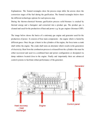
SlideShare a Scribd company logo
A report on
Bio Gasified Coupled engines
Submitted in partial fulfilment of the requirements
For the term work of the subject
IC Engines
Third Year
Mechanical Engineering
Semester V
By
Sr. No Name Roll Number
1 Kevin Lobo 56
2 Nandu Vijay 65
3 Vishnu RC Vijayan 74
Mechanical Engineering
Don Bosco Institute of Technology
Kurla (West), Mumbai-70
2015
INDEX
Sr.
No
Contents
Pg
No
1 ABSTRACT 3
2 INTRODUCTION 4
3 WORKING 6
4 PROCESS ZONES 8
5 LIMITATIONS 13
6 CONCLUSION 15
7 FUTURE SCOPE 16
8 REFERENCES 19
ABSTRACT
Modern agriculture is an extremely energy intensive process. However high agricultural
productivities and subsequently the growth of green revolution has been made possible only by
large amount of energy inputs, especially those from fossil fuels.
With recent price rise and scarcity of these fuels there has been a trend towards use of alternative
energy sources like solar, wind, geothermal etc. However these energy resources have not been
able to provide an economically viable solution for agricultural applications. One biomass energy
based system, which has been proven reliable and had been extensively used for transportation and
on farm systems during World War II is wood or biomass gasification.
Biomass gasification means incomplete combustion of biomass resulting in production of
combustible gases consisting of Carbon monoxide (CO), Hydrogen (H2) and traces of Methane
(CH4). This mixture is called producer gas. Producer gas can be used to run internal combustion
engines (both compression and spark ignition), can be used as substitute for furnace oil in direct
heat applications and can be used to produce, in an economically viable way, methanol – an
extremely attractive chemical which is useful both as fuel for heat engines as well as chemical
feedstock for industries.
Since any biomass material can undergo gasification, this process is much more attractive than
ethanol production or biogas where only selected biomass materials can produce the fuel. Besides,
there is a problem that solid wastes (available on the farm) are seldom in a form that can be readily
utilized economically e.g. Wood wastes can be used in hog fuel boiler but the equipment is
expensive and energy recovery is low.
As a result it is often advantageous to convert this waste into more readily usable fuel from like
producer gas. Hence the attractiveness of gasification. However under present conditions,
economic factors seem to provide the strongest argument of considering gasification. In many
situations where the price of petroleum fuels is high or where supplies are unreliable the biomass
gasification can provide an economically viable system – provided the suitable biomass feedstock
is easily available (as is indeed the case in agricultural systems).
INTRODUCTION
Bio gasified coupled engines:-
Bio means any organic matter which includes life and living organisms, including their
structure, function, growth, evolution, distribution, and taxonomy. Gasification is a process
that converts organic or fossil fuel based carbonaceous materials into carbon
monoxide, hydrogen and carbon dioxide.
Bio gasifier coupled engines is conversion of this bio or organic fuel into producer gas or
syngas fuels (fuel gas mixture consisting primarily of hydrogen, carbon monoxide, and
very often some carbon dioxide) which are coupled to engines to develop power.
These engines range inpower from 0.25 to 4 MW and run on
 Natural Gas
 Biogas
 Landfill Gas
 Coal Mine Gas
 Sewage Gas
 Combustible
 Industrial Waste Gases and Site-Specific Special Gases.
BIOGAS
The term "biogas" refers to gases created by the anaerobic fermentation of biological
materials. Their main constituents are methane and carbon dioxide. Considerable quantities
of biogas are produced by sludge digestion in the tanks of sewage treatment plants (sewage
gas) and anaerobic fermentation of agricultural waste and organic residues in garbage tips
(landfill gas). Since biomass is a source of energy with no net carbon dioxide emissions,
its use as a fuel can help reduce the use offossilfuels, thus helping to reduce the greenhouse
effect.
GASIFICATION
Gasification is achieved by reacting the material at high temperatures (>700 °C), without
combustion, with a controlled amount of oxygen and/or steam. The resulting gas mixture
is called syngas (from synthesis gas or synthetic gas) or producer gas and is itself a fuel.
The power derived from gasification and combustion of the resultant gas is considered to
be a source of renewable energy if the gasified compounds were obtained from biomass.
Syngas may be burned directly in gas engines, used to produce methanol and hydrogen, or
converted via the Fischer–Tropsch process (The Fischer–Tropsch process is a collection
of chemical reactions that converts a mixture of carbon monoxide and hydrogen into
liquid hydrocarbons) into synthetic fuel. Biodegradable waste and the high-temperature
process refines out corrosive ash elements such as chloride and potassium, allowing clean
gas production from otherwise problematic fuels
WORKING
Biogas Types
 Agricultural
 Distillery waste biogas
 MBT-AD
 Biogas from Food Waste / CHP
Biogas formation
Biogas composition
Biogas consists primarily of methane (the source of energy within the fuel) and carbon
dioxide. It also may contain small amounts of nitrogen or hydrogen. Contaminants in the
biogas can include sulphur or siloxanes, but this will depend upon the digester feedstock.
The relative percentages of methane and carbon dioxide in the biogas are influenced by a
number of factors including:
The ratio of carbohydrates, proteins and fats in the feedstock
The dilution factor in the digester (carbon dioxide can be absorbed by water)
GASIFICATION TECHNOLOGIES
The fuel particles in fixed bed gasifier are not moved by the gas flow and thus the fuel in
the gasifier is arranged as fixed bed. The fuel feeding of most reactors is positioned above
the fuel bed while the char coal and the ash are extracted from the bottom of the fuel bed.
Process Zones
Four distinct processes take place in a gasifier as the fuel makes its way to gasification.
They are:
a) Drying of fuel
b) Pyrolysis – A process in which tar and other volatiles are driven off
c) Combustion
d) Reduction – Though there is a considerable overlap of the processes, each can be
assumed to occupy a separate zone where fundamentally different chemical and thermal
reactions take place. Figure shows schematically an updraft gasifier with different zones
and their respective temperatures.
In the downdraft gasifier there are two types :
a) Single throat and
b) Double throat
Single throat gasifiers are mainly used for stationary applications whereas double throat
are for varying loads as well as automotive purposes.
Reaction Chemistry
The following major reactions take place in combustion and reduction zone.
Combustion zone
The combustible substance of a solid fuel is usually composed of elements carbon,
hydrogen and oxygen. In complete combustion carbon dioxide is obtained from carbon in
fuel and water is obtained from the hydrogen, usually as steam. The combustion reaction
is exothermic and yields a theoretical oxidation temperature of 14500 C14. The main
reactions, therefore, are:
C + O2 = CO2 (+ 393 MJ/kg mole)
2H2 + O2 = 2H2 O (- 242 MJ/kg mole)
Reaction zone
The products of partial combustion (water, carbon dioxide and uncombusted partially
cracked pyrolysis products) now pass through a red-hot charcoal bed where the following
reduction reactions take place.
C + CO2 = 2CO (- 164.9 MJ/kg mole)
C + H2O = CO + H2 (- 122.6 MJ/kg mole)
CO + H2O = CO + H2 (+ 42 MJ/kg mole)
C + 2H2 = CH4 (+ 75 MJ/kg mole)
CO2 + H2 = CO + H2O (- 42.3 MJ/kg mole)
Consequently the temperatures in the reduction zone are normally 800-10000 C.
Lower the reduction zone temperature (~ 700-8000 C), lower is the calorific value of gas.
Pyrolysis zone
Wood pyrolysis is an intricate process that is still not completely understood. The products
depend upon temperature, pressure, residence time and heat losses. However following
general remarks can be made about them. Upto the temperature of 2000 C only water is
driven off. Between 200 to 2800 C carbon dioxide, acetic acid and water are given off. The
real pyrolysis, which takes place between 280 to 5000 C, produces large quantities of tar
and gases containing carbon dioxide. Besides light tars, some methyl alcohol is also
formed. Between, 500 to 7000 C the gas production is small and contains hydrogen. Thus
it is easy to see that updraft gasifier will produce much more tar than downdraft one. In
downdraft gasifier the tars have to go through combustion and reduction zone and are
partially broken down.
The four stages of the gasification process take place in a distinguishable –
Reduction or combustion zone.
Figure: Basic process steps of a biomass gasification plant
Explanations: The framed rectangles show the process steps while the arrows show the
conversion stages of the fuel during the gasification. The framed rectangles below show
the different technologic options for each process step.
During the thermo-chemical biomass gasification process solid biomass is cracked by
thermal energy and a fumigator and converted into a product gas. The product gas is
cleaned and used for the production of heat and power e.g. by gas engines (biomass CHP).
The image below shows the basics of a stationary gas engine and generator used for the
production of power. It consists of four main components - the engine which is fueled by
different gases. Once the gas is burnt in the cylinders of the engine, the force turns a crank
shaft within the engine. The crank shaft turns an alternator which results in the generation
of electricity. Heat from the combustion process is releasedfrom the cylinders this must be
either recovered and used in a combined heat and power configuration or dissipated via
dump radiators located close to the engine. Finally and importantly there are advanced
control systems to facilitate robust performance of the generator.
Gas Engine Energy Balance
LIMITATIONS
Gasification is a complex and sensitive process. There exists high level of disagreement
about gasification among engineers, researchers, and manufacturers. Several
manufacturers claim that their unit can be operated on all kinds of biomass. But it is a
questionable fact as physical and chemical properties varies fuel to fuel.
Gasifiers require at least half an hour or more to start the process. Raw material is bulky
and frequent refueling is often required for continuous running of the system. Handling
residues such as ash, tarry condensates is time consuming and dirty work. Driving with
producer gas fueled vehicles requires much more and frequent attention than gasoline or
diesel fueled vehicles.
Getting the producer gas is not difficult, but obtaining in the proper state is the challenging
task. The physical and chemical properties of producer gas such as energy content, gas
composition and impurities vary time to time. All the gasifiers have fairly strict
requirements for fuel size, moisture and ash content. Inadequate fuel preparation is an
important cause of technical problems with gasifiers
Gasifier is too often thought of as simple device that can generate a combustible gas from
any biomass fuel. A hundred years of research has clearly shown that key to successful
gasification is gasifier specifically designed for a particular type of fuel. Hence, biomass
gasification technology requires hard work and tolerance.
Fixed Bed - Updraft fixed bed gasifiers
Major drawbacks are the high amounts of tar and pyrolysis products that occur because the
pyrolysis gas does not pass the hearth zone and thereforeis not combusted. This is of minor
importance if the gas is used for direct heat applications in which the tar is simply burned.
But when the gas is used for engines, extensive gas cleaning is required.
Fixed Bed - Downdraft fixed bed gasifiers
High amounts of ash and dust particles remain in the gas because the gas has to pass the
oxidation zone, where it collects small ash particles
Fuel requirements are relatively strict; fuel must be uniformly sized from 4 to 10 cm so as
not to block the throat and allow pyrolysis gases to flow downward and heat from the hearth
zone to flow upward; therefore, pelletization or briquetting of is often necessary.
The moisture content of the biomass must be less than 25 percent (on a wet basis).
The relatively high temperature of the exit flue gas results in lower gasification efficiency.
Fluidized bed gasifiers
High tar and dust content of the producer gas could result in problems while using the gas
in the engines.
High producer-gas temperatures, which leave alkali metals in the vapor state
Incomplete carbon burnout results in lesser energy output
Complex operation because of the need to control the supply of both air and solid fuel
Need for power consumption for the compression of the gas stream.
CONCLUSION
Biomass gasification offers the most attractive alternative energy system for agricultural
purposes. Most preferred fuels for gasification have been charcoal and wood. However
biomass residues are the most appropriate fuels for on-farm systems and offer the greatest
challenge to researchers and gasification system manufacturers. Very limited experience
has been gained in gasification of biomass residues.
Most extensively used and researched systems have been based on downdraft gasification.
However it appears that for fuels with high ash content fluidized bed combustion may offer
a solution. At present no reliable and economically feasible systems exist.
Biggest challenge in gasification systems lies in developing reliable and economically
cheap cooling and cleaning trains. Maximum usage of producer gas has been in driving
internal combustion engine, both for agricultural as well as for automotive uses. However
direct heat applications like grain drying etc. are very attractive for agricultural systems.
A spark ignition engine running on producer gas on an average produces 0.55-0.75 kWh
of energy from 1 kg of biomass. 8. Compression ignition (diesel) engines cannot run
completely on producer gas. Thus to produce 1 kWh of energy they consume 1 kg of
biomass and 0.07 liters of diesel. Consequently they effect 80-85% diesel saving. 9. Future
applications like methanol production, using producer gas in fuel cell and small scale
irrigation systems for developing countries offer the greatest potentialities.
FUTURE SCOPE
Gas engines are typically applied as stationary continuous generation units but can also
operate as peaking plants & in greenhouses to meet fluctuations in local electricity
demand. They can produce electricity in parallel with the local electricity grid, in island
mode operation, or for power generation in remote areas.
Procedure for the selectionand evaluation of biomass gasification technologies
The following procedure is recommended for the evaluation of the feasibility of
biomass gasificationtechnologies:
Technological evaluation and comparison of different biomass gasification systems –
important, since many systems are still under development and not ready to hit the market
Economical evaluation of the gasification technologies compared to a reference system
(e.g. biomass CHP plant based on combustion) – important, since a high electricefficiency
does not necessarily mean a better economic performance (investment and operation costs
have to be considered as well)
Evaluation of already available reference plants for a particular gasification technology –
important, in order to obtain information regarding reliability and availability
Verification of the emissions (exhaust gas, waste water, ash) of gasification plants
compared to expected emissionlimits and guiding values respectively – important since an
ecological operation based on economically meaningful site constraints is required
Overall evaluation of the systems based on the results of topics 1) to 4)
Working fieldof the BIOS BIOENERGIESYSTEME GmbH
Development, comparison as well as technical and economical evaluation of different
biomass gasification technologies as a basis for the selectionof an adequate technology
Planning of thermal oil systems for the internal heat supply, heat recovery and power
production based on the ORC process
Feasibilitystudies
Preliminaryplant design
Preparation of permit applications
Detaileddesign, request for proposals (RFP)
Supervision of plant constructionand commissioning
Plant monitoring, process and performance optimization
FIELD OF APPLICATION
The industrial waste heat utilisation is especiallyrelevant for industrial processeswith high
heat demands. This includes the following industry sectors:
 Iron and Steel industry
 Cement and building material industry
 Food and beverage processing industry
 Pulp and paper industry
 Chemical industry
 Petroleum industry
Realised projects and proposals under design
Waste heat recovery for district heat utilisation and design of pipe network / BIOCHEMIE
Kundl GmbH (Tyrol, Austria)
Waste heat recovery by flue gas condensation / Holzindustrie KAINDL (Salzburg, Austria)
Heat recovery from an existing CHP-plant / Domat (Grisons, Switzerland)
Heat and power production by waste heat recovery of industrial flue gas streams based on
an ORC cycle – RHI AG, Radenthein (Carinthia, Austria). Heat and power production by
waste heat recovery of industrial flue gas streams based on an ORC cycle, Wietersdorf
(Carinthia, Austria)
Heat and power production by waste heat recovery of industrial waste heat based on an
ORC cycle, Secunda (Mpumalanga, South Africa. Steam generation with waste heat from
an existing biogas plant with gas engine, Holsworthy (Devon, England)
References:
http://www.kogeneracija.rs/english.html
https://www.clarke-energy.com/gas-engines/
http://www.bios-bioenergy.at/en/biomass-gasification.html
https://www.google.co.in/#q=pyrolysis
www.dlbio-dryer.com/Biomass_Gassifier
www.fao.org/docrep/t4470e/t4470e0i.htm
www.nariphaltan.org/gasbook.pdf

More Related Content

What's hot

Waste to fuel
Waste to fuel Waste to fuel
Waste to fuel
Huda Rayeen
 
Biogas plant Classification
Biogas plant ClassificationBiogas plant Classification
Biogas plant Classification
HARI NUNAVATH
 
Biomass cogeneration
Biomass cogenerationBiomass cogeneration
Biomass cogeneration
Y Salman Baig
 
BIOMASS ENERGY AND BIOMASS CONVERSION
BIOMASS ENERGY AND BIOMASS CONVERSIONBIOMASS ENERGY AND BIOMASS CONVERSION
BIOMASS ENERGY AND BIOMASS CONVERSION
Munib Munir
 
Gasifiers
GasifiersGasifiers
Gasifiers
Ajay Singh Lodhi
 
Bio gas plant
Bio gas plantBio gas plant
Bio gas plant
sumitvikram
 
Biomass conversion technologies
Biomass conversion technologiesBiomass conversion technologies
Biomass conversion technologies
Pakistan Ordnance Factories
 
Biomass conversion for energy
Biomass conversion  for energyBiomass conversion  for energy
Biomass conversion for energy
H Janardan Prabhu
 
Biomass energy and conversion processes
Biomass energy and conversion processesBiomass energy and conversion processes
Biomass energy and conversion processes
Mujeeb UR Rahman
 
Bio-Gas
Bio-Gas Bio-Gas
Bio-Gas
vigyanashram
 
Pyrolysis ppt
Pyrolysis pptPyrolysis ppt
Pyrolysis ppt
RuchikaZalpouri
 
WASTE TO ENERGY
WASTE TO ENERGYWASTE TO ENERGY
WASTE TO ENERGY
Pratik Kundu
 
BioMass - Generation and Utilization
BioMass - Generation and UtilizationBioMass - Generation and Utilization
BioMass - Generation and Utilization
S.Vijaya Bhaskar
 
Biogas technology
Biogas technologyBiogas technology
Biogas technology
H Janardan Prabhu
 
Thermochemical conversion of biomass
Thermochemical conversion of biomassThermochemical conversion of biomass
Thermochemical conversion of biomass
Awais Salman
 
Biomass conversion technologies renewable energy resources
Biomass conversion technologies renewable energy resourcesBiomass conversion technologies renewable energy resources
Biomass conversion technologies renewable energy resources
DrBilalAhmadZafarAmi
 
Fluidized bed combustor
Fluidized bed combustorFluidized bed combustor
Fluidized bed combustor
Akash Raj
 
Biomass energy and biouels
Biomass energy and biouelsBiomass energy and biouels
Biomass energy and biouels
Ashish Bandewar
 
Thermo chemical conversion
Thermo chemical conversionThermo chemical conversion
Thermo chemical conversion
nagendran mohan
 

What's hot (20)

Waste to fuel
Waste to fuel Waste to fuel
Waste to fuel
 
Biogas plant Classification
Biogas plant ClassificationBiogas plant Classification
Biogas plant Classification
 
Biomass cogeneration
Biomass cogenerationBiomass cogeneration
Biomass cogeneration
 
BIOMASS ENERGY AND BIOMASS CONVERSION
BIOMASS ENERGY AND BIOMASS CONVERSIONBIOMASS ENERGY AND BIOMASS CONVERSION
BIOMASS ENERGY AND BIOMASS CONVERSION
 
Gasifiers
GasifiersGasifiers
Gasifiers
 
Bio gas plant
Bio gas plantBio gas plant
Bio gas plant
 
Biomass conversion technologies
Biomass conversion technologiesBiomass conversion technologies
Biomass conversion technologies
 
Biomass conversion for energy
Biomass conversion  for energyBiomass conversion  for energy
Biomass conversion for energy
 
Biomass energy and conversion processes
Biomass energy and conversion processesBiomass energy and conversion processes
Biomass energy and conversion processes
 
Bio-Gas
Bio-Gas Bio-Gas
Bio-Gas
 
Pyrolysis ppt
Pyrolysis pptPyrolysis ppt
Pyrolysis ppt
 
WASTE TO ENERGY
WASTE TO ENERGYWASTE TO ENERGY
WASTE TO ENERGY
 
BioMass - Generation and Utilization
BioMass - Generation and UtilizationBioMass - Generation and Utilization
BioMass - Generation and Utilization
 
Bio energy
Bio energyBio energy
Bio energy
 
Biogas technology
Biogas technologyBiogas technology
Biogas technology
 
Thermochemical conversion of biomass
Thermochemical conversion of biomassThermochemical conversion of biomass
Thermochemical conversion of biomass
 
Biomass conversion technologies renewable energy resources
Biomass conversion technologies renewable energy resourcesBiomass conversion technologies renewable energy resources
Biomass conversion technologies renewable energy resources
 
Fluidized bed combustor
Fluidized bed combustorFluidized bed combustor
Fluidized bed combustor
 
Biomass energy and biouels
Biomass energy and biouelsBiomass energy and biouels
Biomass energy and biouels
 
Thermo chemical conversion
Thermo chemical conversionThermo chemical conversion
Thermo chemical conversion
 

Viewers also liked

Rhgs 3 k we of energy generation
Rhgs 3 k we of energy generationRhgs 3 k we of energy generation
Rhgs 3 k we of energy generationElmer Castillo
 
Combined draftgasifier
Combined draftgasifierCombined draftgasifier
Combined draftgasifierBhaskar Social
 
Sistem Pengendalian Intern Pemerintah
Sistem Pengendalian Intern PemerintahSistem Pengendalian Intern Pemerintah
Sistem Pengendalian Intern Pemerintah
Dadang Solihin
 
NILAI AKHIR CBI (1) - FKIP PI - UMRI 3A - 2015
NILAI AKHIR CBI (1) - FKIP PI - UMRI 3A - 2015NILAI AKHIR CBI (1) - FKIP PI - UMRI 3A - 2015
NILAI AKHIR CBI (1) - FKIP PI - UMRI 3A - 2015
eka pandu cynthia
 
Puran singh resume
Puran singh resumePuran singh resume
Puran singh resumepuran1976
 
REKAP NILAI (SEMENTARA) PENGANTAR TEKNOLOGI INFORMASI - FKIP PI UMRI 1A - 2015
REKAP NILAI (SEMENTARA) PENGANTAR TEKNOLOGI INFORMASI - FKIP PI UMRI 1A - 2015REKAP NILAI (SEMENTARA) PENGANTAR TEKNOLOGI INFORMASI - FKIP PI UMRI 1A - 2015
REKAP NILAI (SEMENTARA) PENGANTAR TEKNOLOGI INFORMASI - FKIP PI UMRI 1A - 2015
eka pandu cynthia
 
Kajian Pembangunan
Kajian PembangunanKajian Pembangunan
Kajian Pembangunan
Dadang Solihin
 
uso del portafolio en clase
uso del portafolio en claseuso del portafolio en clase
uso del portafolio en clase
FLOR2017
 
PPS (PATRIOT PUBLIC SERVANT) RAO PIYA JEE
PPS (PATRIOT PUBLIC SERVANT) RAO PIYA JEEPPS (PATRIOT PUBLIC SERVANT) RAO PIYA JEE
PPS (PATRIOT PUBLIC SERVANT) RAO PIYA JEE
PPS
 
Arah Kebijakan RKP dalam Penyusunan RKPD dan APBD 2010
Arah Kebijakan RKP dalam Penyusunan RKPD dan APBD 2010Arah Kebijakan RKP dalam Penyusunan RKPD dan APBD 2010
Arah Kebijakan RKP dalam Penyusunan RKPD dan APBD 2010
Dadang Solihin
 
Project management Using Pert
Project management Using PertProject management Using Pert
Project management Using Pert
Vishnu RC Vijayan
 
Ppt pak abdam
Ppt pak abdamPpt pak abdam
Ppt pak abdam
Indra Abdam Muwakhid
 
Mechatronics case study on Wireless Survillence Balloon
Mechatronics case study on Wireless Survillence BalloonMechatronics case study on Wireless Survillence Balloon
Mechatronics case study on Wireless Survillence Balloon
Vishnu RC Vijayan
 
Program Pembelian Tiket Menggunakan Borland C++
Program Pembelian Tiket Menggunakan Borland C++Program Pembelian Tiket Menggunakan Borland C++
Program Pembelian Tiket Menggunakan Borland C++
Muhammad Iqbal
 
Mahesh paddy
Mahesh paddyMahesh paddy
Mahesh paddy
Mahesh Mukundan
 
Perencanaan Spasial Kawasan Khusus
Perencanaan Spasial Kawasan KhususPerencanaan Spasial Kawasan Khusus
Perencanaan Spasial Kawasan Khusus
Dadang Solihin
 
Aspek akuntansi
Aspek akuntansiAspek akuntansi
Aspek akuntansi
Indra Abdam Muwakhid
 
سیستمهای مدیریت دانش
سیستمهای مدیریت دانشسیستمهای مدیریت دانش
سیستمهای مدیریت دانش
Javad Sha'bani
 

Viewers also liked (20)

Rhgs 3 k we of energy generation
Rhgs 3 k we of energy generationRhgs 3 k we of energy generation
Rhgs 3 k we of energy generation
 
Combined draftgasifier
Combined draftgasifierCombined draftgasifier
Combined draftgasifier
 
Sistem Pengendalian Intern Pemerintah
Sistem Pengendalian Intern PemerintahSistem Pengendalian Intern Pemerintah
Sistem Pengendalian Intern Pemerintah
 
NILAI AKHIR CBI (1) - FKIP PI - UMRI 3A - 2015
NILAI AKHIR CBI (1) - FKIP PI - UMRI 3A - 2015NILAI AKHIR CBI (1) - FKIP PI - UMRI 3A - 2015
NILAI AKHIR CBI (1) - FKIP PI - UMRI 3A - 2015
 
Puran singh resume
Puran singh resumePuran singh resume
Puran singh resume
 
REKAP NILAI (SEMENTARA) PENGANTAR TEKNOLOGI INFORMASI - FKIP PI UMRI 1A - 2015
REKAP NILAI (SEMENTARA) PENGANTAR TEKNOLOGI INFORMASI - FKIP PI UMRI 1A - 2015REKAP NILAI (SEMENTARA) PENGANTAR TEKNOLOGI INFORMASI - FKIP PI UMRI 1A - 2015
REKAP NILAI (SEMENTARA) PENGANTAR TEKNOLOGI INFORMASI - FKIP PI UMRI 1A - 2015
 
Kajian Pembangunan
Kajian PembangunanKajian Pembangunan
Kajian Pembangunan
 
uso del portafolio en clase
uso del portafolio en claseuso del portafolio en clase
uso del portafolio en clase
 
PPS (PATRIOT PUBLIC SERVANT) RAO PIYA JEE
PPS (PATRIOT PUBLIC SERVANT) RAO PIYA JEEPPS (PATRIOT PUBLIC SERVANT) RAO PIYA JEE
PPS (PATRIOT PUBLIC SERVANT) RAO PIYA JEE
 
Arah Kebijakan RKP dalam Penyusunan RKPD dan APBD 2010
Arah Kebijakan RKP dalam Penyusunan RKPD dan APBD 2010Arah Kebijakan RKP dalam Penyusunan RKPD dan APBD 2010
Arah Kebijakan RKP dalam Penyusunan RKPD dan APBD 2010
 
Salah Shawky
Salah ShawkySalah Shawky
Salah Shawky
 
DCC Projects
DCC ProjectsDCC Projects
DCC Projects
 
Project management Using Pert
Project management Using PertProject management Using Pert
Project management Using Pert
 
Ppt pak abdam
Ppt pak abdamPpt pak abdam
Ppt pak abdam
 
Mechatronics case study on Wireless Survillence Balloon
Mechatronics case study on Wireless Survillence BalloonMechatronics case study on Wireless Survillence Balloon
Mechatronics case study on Wireless Survillence Balloon
 
Program Pembelian Tiket Menggunakan Borland C++
Program Pembelian Tiket Menggunakan Borland C++Program Pembelian Tiket Menggunakan Borland C++
Program Pembelian Tiket Menggunakan Borland C++
 
Mahesh paddy
Mahesh paddyMahesh paddy
Mahesh paddy
 
Perencanaan Spasial Kawasan Khusus
Perencanaan Spasial Kawasan KhususPerencanaan Spasial Kawasan Khusus
Perencanaan Spasial Kawasan Khusus
 
Aspek akuntansi
Aspek akuntansiAspek akuntansi
Aspek akuntansi
 
سیستمهای مدیریت دانش
سیستمهای مدیریت دانشسیستمهای مدیریت دانش
سیستمهای مدیریت دانش
 

Similar to Bio-gasifier Coupled Engine

Gasification and types of gasifiers
Gasification and types of gasifiersGasification and types of gasifiers
Gasification and types of gasifiers
Ajay Singh Lodhi
 
Thermochemical
ThermochemicalThermochemical
BIOMASS ENERGY.pptx
BIOMASS ENERGY.pptxBIOMASS ENERGY.pptx
BIOMASS ENERGY.pptx
ssusereabf98
 
Waste to energy
Waste to energyWaste to energy
Waste to energy
HarithaMNair
 
Increasing Calorific Value of Biogas using Different Techniques: A Review
Increasing Calorific Value of Biogas using Different Techniques: A ReviewIncreasing Calorific Value of Biogas using Different Techniques: A Review
Increasing Calorific Value of Biogas using Different Techniques: A Review
ijsrd.com
 
Gasification ieee4
Gasification ieee4Gasification ieee4
Gasification ieee4
John Fredy Castillo Muñoz
 
Biomass conversion technologies
Biomass conversion technologiesBiomass conversion technologies
Biomass conversion technologies
Pakistan Ordnance Factories
 
H012445056
H012445056H012445056
H012445056
IOSR Journals
 
Module - 4 Biomass.pptx
Module - 4 Biomass.pptxModule - 4 Biomass.pptx
Module - 4 Biomass.pptx
4JN20CS084RohitD
 
Raunak_Bhatia_Energy_Engineering_PPT.pptx
Raunak_Bhatia_Energy_Engineering_PPT.pptxRaunak_Bhatia_Energy_Engineering_PPT.pptx
Raunak_Bhatia_Energy_Engineering_PPT.pptx
RaunakBhatia5
 
White hydrogen
White hydrogenWhite hydrogen
White hydrogen
Recupera
 
Pyrolysis of-biomass
Pyrolysis of-biomassPyrolysis of-biomass
Pyrolysis of-biomass
H Janardan Prabhu
 
Gasification the Flexible Answer to Biomass Conversion
Gasification the Flexible Answer to Biomass ConversionGasification the Flexible Answer to Biomass Conversion
Gasification the Flexible Answer to Biomass Conversionbigterguy
 
Fabrication and Performance Analysis of Downdraft Biomass Gasifier Using Suga...
Fabrication and Performance Analysis of Downdraft Biomass Gasifier Using Suga...Fabrication and Performance Analysis of Downdraft Biomass Gasifier Using Suga...
Fabrication and Performance Analysis of Downdraft Biomass Gasifier Using Suga...
IJSRD
 
Fabrication and Performance Analysis of Downdraft Biomass Gasifier Using Suga...
Fabrication and Performance Analysis of Downdraft Biomass Gasifier Using Suga...Fabrication and Performance Analysis of Downdraft Biomass Gasifier Using Suga...
Fabrication and Performance Analysis of Downdraft Biomass Gasifier Using Suga...
IJSRD
 
HYDROGEN GAS PRODUCTION BY PARTIAL OXIDATION OF HEAVY FUEL OIL
HYDROGEN GAS PRODUCTION BY PARTIAL OXIDATION OF HEAVY FUEL OILHYDROGEN GAS PRODUCTION BY PARTIAL OXIDATION OF HEAVY FUEL OIL
HYDROGEN GAS PRODUCTION BY PARTIAL OXIDATION OF HEAVY FUEL OIL
Adebayo Bamidele Olanrewaju BSc, ASM, AMNIM, MNSE, MNSChE, CSSBB
 
Biomass energy
Biomass energyBiomass energy
Biomass energy
Ramaraj90033
 
White hydrogen
White hydrogenWhite hydrogen
White hydrogen
Recupera
 
Bio-Mass Energy -2.docx
Bio-Mass Energy -2.docxBio-Mass Energy -2.docx
Bio-Mass Energy -2.docx
ProfVilasShamraoPati
 
Biomass Utilization.ppt
Biomass Utilization.pptBiomass Utilization.ppt
Biomass Utilization.ppt
DheerajAhuja27
 

Similar to Bio-gasifier Coupled Engine (20)

Gasification and types of gasifiers
Gasification and types of gasifiersGasification and types of gasifiers
Gasification and types of gasifiers
 
Thermochemical
ThermochemicalThermochemical
Thermochemical
 
BIOMASS ENERGY.pptx
BIOMASS ENERGY.pptxBIOMASS ENERGY.pptx
BIOMASS ENERGY.pptx
 
Waste to energy
Waste to energyWaste to energy
Waste to energy
 
Increasing Calorific Value of Biogas using Different Techniques: A Review
Increasing Calorific Value of Biogas using Different Techniques: A ReviewIncreasing Calorific Value of Biogas using Different Techniques: A Review
Increasing Calorific Value of Biogas using Different Techniques: A Review
 
Gasification ieee4
Gasification ieee4Gasification ieee4
Gasification ieee4
 
Biomass conversion technologies
Biomass conversion technologiesBiomass conversion technologies
Biomass conversion technologies
 
H012445056
H012445056H012445056
H012445056
 
Module - 4 Biomass.pptx
Module - 4 Biomass.pptxModule - 4 Biomass.pptx
Module - 4 Biomass.pptx
 
Raunak_Bhatia_Energy_Engineering_PPT.pptx
Raunak_Bhatia_Energy_Engineering_PPT.pptxRaunak_Bhatia_Energy_Engineering_PPT.pptx
Raunak_Bhatia_Energy_Engineering_PPT.pptx
 
White hydrogen
White hydrogenWhite hydrogen
White hydrogen
 
Pyrolysis of-biomass
Pyrolysis of-biomassPyrolysis of-biomass
Pyrolysis of-biomass
 
Gasification the Flexible Answer to Biomass Conversion
Gasification the Flexible Answer to Biomass ConversionGasification the Flexible Answer to Biomass Conversion
Gasification the Flexible Answer to Biomass Conversion
 
Fabrication and Performance Analysis of Downdraft Biomass Gasifier Using Suga...
Fabrication and Performance Analysis of Downdraft Biomass Gasifier Using Suga...Fabrication and Performance Analysis of Downdraft Biomass Gasifier Using Suga...
Fabrication and Performance Analysis of Downdraft Biomass Gasifier Using Suga...
 
Fabrication and Performance Analysis of Downdraft Biomass Gasifier Using Suga...
Fabrication and Performance Analysis of Downdraft Biomass Gasifier Using Suga...Fabrication and Performance Analysis of Downdraft Biomass Gasifier Using Suga...
Fabrication and Performance Analysis of Downdraft Biomass Gasifier Using Suga...
 
HYDROGEN GAS PRODUCTION BY PARTIAL OXIDATION OF HEAVY FUEL OIL
HYDROGEN GAS PRODUCTION BY PARTIAL OXIDATION OF HEAVY FUEL OILHYDROGEN GAS PRODUCTION BY PARTIAL OXIDATION OF HEAVY FUEL OIL
HYDROGEN GAS PRODUCTION BY PARTIAL OXIDATION OF HEAVY FUEL OIL
 
Biomass energy
Biomass energyBiomass energy
Biomass energy
 
White hydrogen
White hydrogenWhite hydrogen
White hydrogen
 
Bio-Mass Energy -2.docx
Bio-Mass Energy -2.docxBio-Mass Energy -2.docx
Bio-Mass Energy -2.docx
 
Biomass Utilization.ppt
Biomass Utilization.pptBiomass Utilization.ppt
Biomass Utilization.ppt
 

More from Vishnu RC Vijayan

Procurement and Supply Chain
Procurement and Supply ChainProcurement and Supply Chain
Procurement and Supply Chain
Vishnu RC Vijayan
 
Hand Pump Design
Hand Pump DesignHand Pump Design
Hand Pump Design
Vishnu RC Vijayan
 
HSL & HSV colour models
HSL & HSV colour modelsHSL & HSV colour models
HSL & HSV colour models
Vishnu RC Vijayan
 
Energy conservation in compressed air systems
Energy conservation in compressed air systemsEnergy conservation in compressed air systems
Energy conservation in compressed air systems
Vishnu RC Vijayan
 
Liquefied petroleum gas cylinder
Liquefied petroleum gas cylinderLiquefied petroleum gas cylinder
Liquefied petroleum gas cylinder
Vishnu RC Vijayan
 
Fea course project on Leaf Spring
Fea course project on Leaf SpringFea course project on Leaf Spring
Fea course project on Leaf Spring
Vishnu RC Vijayan
 
Ceramics
CeramicsCeramics
shell moulding
shell mouldingshell moulding
shell moulding
Vishnu RC Vijayan
 
Anti rape gloves
Anti rape glovesAnti rape gloves
Anti rape gloves
Vishnu RC Vijayan
 
Hydroforming
HydroformingHydroforming
Hydroforming
Vishnu RC Vijayan
 
Gravity Oscillating mechanism
Gravity Oscillating mechanismGravity Oscillating mechanism
Gravity Oscillating mechanism
Vishnu RC Vijayan
 

More from Vishnu RC Vijayan (11)

Procurement and Supply Chain
Procurement and Supply ChainProcurement and Supply Chain
Procurement and Supply Chain
 
Hand Pump Design
Hand Pump DesignHand Pump Design
Hand Pump Design
 
HSL & HSV colour models
HSL & HSV colour modelsHSL & HSV colour models
HSL & HSV colour models
 
Energy conservation in compressed air systems
Energy conservation in compressed air systemsEnergy conservation in compressed air systems
Energy conservation in compressed air systems
 
Liquefied petroleum gas cylinder
Liquefied petroleum gas cylinderLiquefied petroleum gas cylinder
Liquefied petroleum gas cylinder
 
Fea course project on Leaf Spring
Fea course project on Leaf SpringFea course project on Leaf Spring
Fea course project on Leaf Spring
 
Ceramics
CeramicsCeramics
Ceramics
 
shell moulding
shell mouldingshell moulding
shell moulding
 
Anti rape gloves
Anti rape glovesAnti rape gloves
Anti rape gloves
 
Hydroforming
HydroformingHydroforming
Hydroforming
 
Gravity Oscillating mechanism
Gravity Oscillating mechanismGravity Oscillating mechanism
Gravity Oscillating mechanism
 

Recently uploaded

Gen AI Study Jams _ For the GDSC Leads in India.pdf
Gen AI Study Jams _ For the GDSC Leads in India.pdfGen AI Study Jams _ For the GDSC Leads in India.pdf
Gen AI Study Jams _ For the GDSC Leads in India.pdf
gdsczhcet
 
Student information management system project report ii.pdf
Student information management system project report ii.pdfStudent information management system project report ii.pdf
Student information management system project report ii.pdf
Kamal Acharya
 
Fundamentals of Electric Drives and its applications.pptx
Fundamentals of Electric Drives and its applications.pptxFundamentals of Electric Drives and its applications.pptx
Fundamentals of Electric Drives and its applications.pptx
manasideore6
 
AKS UNIVERSITY Satna Final Year Project By OM Hardaha.pdf
AKS UNIVERSITY Satna Final Year Project By OM Hardaha.pdfAKS UNIVERSITY Satna Final Year Project By OM Hardaha.pdf
AKS UNIVERSITY Satna Final Year Project By OM Hardaha.pdf
SamSarthak3
 
Governing Equations for Fundamental Aerodynamics_Anderson2010.pdf
Governing Equations for Fundamental Aerodynamics_Anderson2010.pdfGoverning Equations for Fundamental Aerodynamics_Anderson2010.pdf
Governing Equations for Fundamental Aerodynamics_Anderson2010.pdf
WENKENLI1
 
Hierarchical Digital Twin of a Naval Power System
Hierarchical Digital Twin of a Naval Power SystemHierarchical Digital Twin of a Naval Power System
Hierarchical Digital Twin of a Naval Power System
Kerry Sado
 
NO1 Uk best vashikaran specialist in delhi vashikaran baba near me online vas...
NO1 Uk best vashikaran specialist in delhi vashikaran baba near me online vas...NO1 Uk best vashikaran specialist in delhi vashikaran baba near me online vas...
NO1 Uk best vashikaran specialist in delhi vashikaran baba near me online vas...
Amil Baba Dawood bangali
 
HYDROPOWER - Hydroelectric power generation
HYDROPOWER - Hydroelectric power generationHYDROPOWER - Hydroelectric power generation
HYDROPOWER - Hydroelectric power generation
Robbie Edward Sayers
 
block diagram and signal flow graph representation
block diagram and signal flow graph representationblock diagram and signal flow graph representation
block diagram and signal flow graph representation
Divya Somashekar
 
English lab ppt no titlespecENG PPTt.pdf
English lab ppt no titlespecENG PPTt.pdfEnglish lab ppt no titlespecENG PPTt.pdf
English lab ppt no titlespecENG PPTt.pdf
BrazilAccount1
 
在线办理(ANU毕业证书)澳洲国立大学毕业证录取通知书一模一样
在线办理(ANU毕业证书)澳洲国立大学毕业证录取通知书一模一样在线办理(ANU毕业证书)澳洲国立大学毕业证录取通知书一模一样
在线办理(ANU毕业证书)澳洲国立大学毕业证录取通知书一模一样
obonagu
 
Final project report on grocery store management system..pdf
Final project report on grocery store management system..pdfFinal project report on grocery store management system..pdf
Final project report on grocery store management system..pdf
Kamal Acharya
 
Planning Of Procurement o different goods and services
Planning Of Procurement o different goods and servicesPlanning Of Procurement o different goods and services
Planning Of Procurement o different goods and services
JoytuBarua2
 
Industrial Training at Shahjalal Fertilizer Company Limited (SFCL)
Industrial Training at Shahjalal Fertilizer Company Limited (SFCL)Industrial Training at Shahjalal Fertilizer Company Limited (SFCL)
Industrial Training at Shahjalal Fertilizer Company Limited (SFCL)
MdTanvirMahtab2
 
Architectural Portfolio Sean Lockwood
Architectural Portfolio Sean LockwoodArchitectural Portfolio Sean Lockwood
Architectural Portfolio Sean Lockwood
seandesed
 
Water Industry Process Automation and Control Monthly - May 2024.pdf
Water Industry Process Automation and Control Monthly - May 2024.pdfWater Industry Process Automation and Control Monthly - May 2024.pdf
Water Industry Process Automation and Control Monthly - May 2024.pdf
Water Industry Process Automation & Control
 
Pile Foundation by Venkatesh Taduvai (Sub Geotechnical Engineering II)-conver...
Pile Foundation by Venkatesh Taduvai (Sub Geotechnical Engineering II)-conver...Pile Foundation by Venkatesh Taduvai (Sub Geotechnical Engineering II)-conver...
Pile Foundation by Venkatesh Taduvai (Sub Geotechnical Engineering II)-conver...
AJAYKUMARPUND1
 
H.Seo, ICLR 2024, MLILAB, KAIST AI.pdf
H.Seo,  ICLR 2024, MLILAB,  KAIST AI.pdfH.Seo,  ICLR 2024, MLILAB,  KAIST AI.pdf
H.Seo, ICLR 2024, MLILAB, KAIST AI.pdf
MLILAB
 
power quality voltage fluctuation UNIT - I.pptx
power quality voltage fluctuation UNIT - I.pptxpower quality voltage fluctuation UNIT - I.pptx
power quality voltage fluctuation UNIT - I.pptx
ViniHema
 
ASME IX(9) 2007 Full Version .pdf
ASME IX(9)  2007 Full Version       .pdfASME IX(9)  2007 Full Version       .pdf
ASME IX(9) 2007 Full Version .pdf
AhmedHussein950959
 

Recently uploaded (20)

Gen AI Study Jams _ For the GDSC Leads in India.pdf
Gen AI Study Jams _ For the GDSC Leads in India.pdfGen AI Study Jams _ For the GDSC Leads in India.pdf
Gen AI Study Jams _ For the GDSC Leads in India.pdf
 
Student information management system project report ii.pdf
Student information management system project report ii.pdfStudent information management system project report ii.pdf
Student information management system project report ii.pdf
 
Fundamentals of Electric Drives and its applications.pptx
Fundamentals of Electric Drives and its applications.pptxFundamentals of Electric Drives and its applications.pptx
Fundamentals of Electric Drives and its applications.pptx
 
AKS UNIVERSITY Satna Final Year Project By OM Hardaha.pdf
AKS UNIVERSITY Satna Final Year Project By OM Hardaha.pdfAKS UNIVERSITY Satna Final Year Project By OM Hardaha.pdf
AKS UNIVERSITY Satna Final Year Project By OM Hardaha.pdf
 
Governing Equations for Fundamental Aerodynamics_Anderson2010.pdf
Governing Equations for Fundamental Aerodynamics_Anderson2010.pdfGoverning Equations for Fundamental Aerodynamics_Anderson2010.pdf
Governing Equations for Fundamental Aerodynamics_Anderson2010.pdf
 
Hierarchical Digital Twin of a Naval Power System
Hierarchical Digital Twin of a Naval Power SystemHierarchical Digital Twin of a Naval Power System
Hierarchical Digital Twin of a Naval Power System
 
NO1 Uk best vashikaran specialist in delhi vashikaran baba near me online vas...
NO1 Uk best vashikaran specialist in delhi vashikaran baba near me online vas...NO1 Uk best vashikaran specialist in delhi vashikaran baba near me online vas...
NO1 Uk best vashikaran specialist in delhi vashikaran baba near me online vas...
 
HYDROPOWER - Hydroelectric power generation
HYDROPOWER - Hydroelectric power generationHYDROPOWER - Hydroelectric power generation
HYDROPOWER - Hydroelectric power generation
 
block diagram and signal flow graph representation
block diagram and signal flow graph representationblock diagram and signal flow graph representation
block diagram and signal flow graph representation
 
English lab ppt no titlespecENG PPTt.pdf
English lab ppt no titlespecENG PPTt.pdfEnglish lab ppt no titlespecENG PPTt.pdf
English lab ppt no titlespecENG PPTt.pdf
 
在线办理(ANU毕业证书)澳洲国立大学毕业证录取通知书一模一样
在线办理(ANU毕业证书)澳洲国立大学毕业证录取通知书一模一样在线办理(ANU毕业证书)澳洲国立大学毕业证录取通知书一模一样
在线办理(ANU毕业证书)澳洲国立大学毕业证录取通知书一模一样
 
Final project report on grocery store management system..pdf
Final project report on grocery store management system..pdfFinal project report on grocery store management system..pdf
Final project report on grocery store management system..pdf
 
Planning Of Procurement o different goods and services
Planning Of Procurement o different goods and servicesPlanning Of Procurement o different goods and services
Planning Of Procurement o different goods and services
 
Industrial Training at Shahjalal Fertilizer Company Limited (SFCL)
Industrial Training at Shahjalal Fertilizer Company Limited (SFCL)Industrial Training at Shahjalal Fertilizer Company Limited (SFCL)
Industrial Training at Shahjalal Fertilizer Company Limited (SFCL)
 
Architectural Portfolio Sean Lockwood
Architectural Portfolio Sean LockwoodArchitectural Portfolio Sean Lockwood
Architectural Portfolio Sean Lockwood
 
Water Industry Process Automation and Control Monthly - May 2024.pdf
Water Industry Process Automation and Control Monthly - May 2024.pdfWater Industry Process Automation and Control Monthly - May 2024.pdf
Water Industry Process Automation and Control Monthly - May 2024.pdf
 
Pile Foundation by Venkatesh Taduvai (Sub Geotechnical Engineering II)-conver...
Pile Foundation by Venkatesh Taduvai (Sub Geotechnical Engineering II)-conver...Pile Foundation by Venkatesh Taduvai (Sub Geotechnical Engineering II)-conver...
Pile Foundation by Venkatesh Taduvai (Sub Geotechnical Engineering II)-conver...
 
H.Seo, ICLR 2024, MLILAB, KAIST AI.pdf
H.Seo,  ICLR 2024, MLILAB,  KAIST AI.pdfH.Seo,  ICLR 2024, MLILAB,  KAIST AI.pdf
H.Seo, ICLR 2024, MLILAB, KAIST AI.pdf
 
power quality voltage fluctuation UNIT - I.pptx
power quality voltage fluctuation UNIT - I.pptxpower quality voltage fluctuation UNIT - I.pptx
power quality voltage fluctuation UNIT - I.pptx
 
ASME IX(9) 2007 Full Version .pdf
ASME IX(9)  2007 Full Version       .pdfASME IX(9)  2007 Full Version       .pdf
ASME IX(9) 2007 Full Version .pdf
 

Bio-gasifier Coupled Engine

  • 1. A report on Bio Gasified Coupled engines Submitted in partial fulfilment of the requirements For the term work of the subject IC Engines Third Year Mechanical Engineering Semester V By Sr. No Name Roll Number 1 Kevin Lobo 56 2 Nandu Vijay 65 3 Vishnu RC Vijayan 74 Mechanical Engineering Don Bosco Institute of Technology Kurla (West), Mumbai-70 2015
  • 2. INDEX Sr. No Contents Pg No 1 ABSTRACT 3 2 INTRODUCTION 4 3 WORKING 6 4 PROCESS ZONES 8 5 LIMITATIONS 13 6 CONCLUSION 15 7 FUTURE SCOPE 16 8 REFERENCES 19
  • 3. ABSTRACT Modern agriculture is an extremely energy intensive process. However high agricultural productivities and subsequently the growth of green revolution has been made possible only by large amount of energy inputs, especially those from fossil fuels. With recent price rise and scarcity of these fuels there has been a trend towards use of alternative energy sources like solar, wind, geothermal etc. However these energy resources have not been able to provide an economically viable solution for agricultural applications. One biomass energy based system, which has been proven reliable and had been extensively used for transportation and on farm systems during World War II is wood or biomass gasification. Biomass gasification means incomplete combustion of biomass resulting in production of combustible gases consisting of Carbon monoxide (CO), Hydrogen (H2) and traces of Methane (CH4). This mixture is called producer gas. Producer gas can be used to run internal combustion engines (both compression and spark ignition), can be used as substitute for furnace oil in direct heat applications and can be used to produce, in an economically viable way, methanol – an extremely attractive chemical which is useful both as fuel for heat engines as well as chemical feedstock for industries. Since any biomass material can undergo gasification, this process is much more attractive than ethanol production or biogas where only selected biomass materials can produce the fuel. Besides, there is a problem that solid wastes (available on the farm) are seldom in a form that can be readily utilized economically e.g. Wood wastes can be used in hog fuel boiler but the equipment is expensive and energy recovery is low. As a result it is often advantageous to convert this waste into more readily usable fuel from like producer gas. Hence the attractiveness of gasification. However under present conditions, economic factors seem to provide the strongest argument of considering gasification. In many situations where the price of petroleum fuels is high or where supplies are unreliable the biomass gasification can provide an economically viable system – provided the suitable biomass feedstock is easily available (as is indeed the case in agricultural systems).
  • 4. INTRODUCTION Bio gasified coupled engines:- Bio means any organic matter which includes life and living organisms, including their structure, function, growth, evolution, distribution, and taxonomy. Gasification is a process that converts organic or fossil fuel based carbonaceous materials into carbon monoxide, hydrogen and carbon dioxide. Bio gasifier coupled engines is conversion of this bio or organic fuel into producer gas or syngas fuels (fuel gas mixture consisting primarily of hydrogen, carbon monoxide, and very often some carbon dioxide) which are coupled to engines to develop power. These engines range inpower from 0.25 to 4 MW and run on  Natural Gas  Biogas  Landfill Gas  Coal Mine Gas  Sewage Gas  Combustible  Industrial Waste Gases and Site-Specific Special Gases.
  • 5. BIOGAS The term "biogas" refers to gases created by the anaerobic fermentation of biological materials. Their main constituents are methane and carbon dioxide. Considerable quantities of biogas are produced by sludge digestion in the tanks of sewage treatment plants (sewage gas) and anaerobic fermentation of agricultural waste and organic residues in garbage tips (landfill gas). Since biomass is a source of energy with no net carbon dioxide emissions, its use as a fuel can help reduce the use offossilfuels, thus helping to reduce the greenhouse effect. GASIFICATION Gasification is achieved by reacting the material at high temperatures (>700 °C), without combustion, with a controlled amount of oxygen and/or steam. The resulting gas mixture is called syngas (from synthesis gas or synthetic gas) or producer gas and is itself a fuel. The power derived from gasification and combustion of the resultant gas is considered to be a source of renewable energy if the gasified compounds were obtained from biomass. Syngas may be burned directly in gas engines, used to produce methanol and hydrogen, or converted via the Fischer–Tropsch process (The Fischer–Tropsch process is a collection of chemical reactions that converts a mixture of carbon monoxide and hydrogen into liquid hydrocarbons) into synthetic fuel. Biodegradable waste and the high-temperature process refines out corrosive ash elements such as chloride and potassium, allowing clean gas production from otherwise problematic fuels
  • 6. WORKING Biogas Types  Agricultural  Distillery waste biogas  MBT-AD  Biogas from Food Waste / CHP Biogas formation Biogas composition Biogas consists primarily of methane (the source of energy within the fuel) and carbon dioxide. It also may contain small amounts of nitrogen or hydrogen. Contaminants in the biogas can include sulphur or siloxanes, but this will depend upon the digester feedstock.
  • 7. The relative percentages of methane and carbon dioxide in the biogas are influenced by a number of factors including: The ratio of carbohydrates, proteins and fats in the feedstock The dilution factor in the digester (carbon dioxide can be absorbed by water) GASIFICATION TECHNOLOGIES The fuel particles in fixed bed gasifier are not moved by the gas flow and thus the fuel in the gasifier is arranged as fixed bed. The fuel feeding of most reactors is positioned above the fuel bed while the char coal and the ash are extracted from the bottom of the fuel bed.
  • 8. Process Zones Four distinct processes take place in a gasifier as the fuel makes its way to gasification. They are: a) Drying of fuel b) Pyrolysis – A process in which tar and other volatiles are driven off c) Combustion d) Reduction – Though there is a considerable overlap of the processes, each can be assumed to occupy a separate zone where fundamentally different chemical and thermal reactions take place. Figure shows schematically an updraft gasifier with different zones and their respective temperatures.
  • 9. In the downdraft gasifier there are two types : a) Single throat and b) Double throat Single throat gasifiers are mainly used for stationary applications whereas double throat are for varying loads as well as automotive purposes. Reaction Chemistry The following major reactions take place in combustion and reduction zone. Combustion zone The combustible substance of a solid fuel is usually composed of elements carbon, hydrogen and oxygen. In complete combustion carbon dioxide is obtained from carbon in fuel and water is obtained from the hydrogen, usually as steam. The combustion reaction is exothermic and yields a theoretical oxidation temperature of 14500 C14. The main reactions, therefore, are: C + O2 = CO2 (+ 393 MJ/kg mole) 2H2 + O2 = 2H2 O (- 242 MJ/kg mole) Reaction zone The products of partial combustion (water, carbon dioxide and uncombusted partially cracked pyrolysis products) now pass through a red-hot charcoal bed where the following reduction reactions take place. C + CO2 = 2CO (- 164.9 MJ/kg mole) C + H2O = CO + H2 (- 122.6 MJ/kg mole) CO + H2O = CO + H2 (+ 42 MJ/kg mole) C + 2H2 = CH4 (+ 75 MJ/kg mole) CO2 + H2 = CO + H2O (- 42.3 MJ/kg mole) Consequently the temperatures in the reduction zone are normally 800-10000 C. Lower the reduction zone temperature (~ 700-8000 C), lower is the calorific value of gas.
  • 10. Pyrolysis zone Wood pyrolysis is an intricate process that is still not completely understood. The products depend upon temperature, pressure, residence time and heat losses. However following general remarks can be made about them. Upto the temperature of 2000 C only water is driven off. Between 200 to 2800 C carbon dioxide, acetic acid and water are given off. The real pyrolysis, which takes place between 280 to 5000 C, produces large quantities of tar and gases containing carbon dioxide. Besides light tars, some methyl alcohol is also formed. Between, 500 to 7000 C the gas production is small and contains hydrogen. Thus it is easy to see that updraft gasifier will produce much more tar than downdraft one. In downdraft gasifier the tars have to go through combustion and reduction zone and are partially broken down. The four stages of the gasification process take place in a distinguishable – Reduction or combustion zone. Figure: Basic process steps of a biomass gasification plant
  • 11. Explanations: The framed rectangles show the process steps while the arrows show the conversion stages of the fuel during the gasification. The framed rectangles below show the different technologic options for each process step. During the thermo-chemical biomass gasification process solid biomass is cracked by thermal energy and a fumigator and converted into a product gas. The product gas is cleaned and used for the production of heat and power e.g. by gas engines (biomass CHP). The image below shows the basics of a stationary gas engine and generator used for the production of power. It consists of four main components - the engine which is fueled by different gases. Once the gas is burnt in the cylinders of the engine, the force turns a crank shaft within the engine. The crank shaft turns an alternator which results in the generation of electricity. Heat from the combustion process is releasedfrom the cylinders this must be either recovered and used in a combined heat and power configuration or dissipated via dump radiators located close to the engine. Finally and importantly there are advanced control systems to facilitate robust performance of the generator.
  • 12. Gas Engine Energy Balance
  • 13. LIMITATIONS Gasification is a complex and sensitive process. There exists high level of disagreement about gasification among engineers, researchers, and manufacturers. Several manufacturers claim that their unit can be operated on all kinds of biomass. But it is a questionable fact as physical and chemical properties varies fuel to fuel. Gasifiers require at least half an hour or more to start the process. Raw material is bulky and frequent refueling is often required for continuous running of the system. Handling residues such as ash, tarry condensates is time consuming and dirty work. Driving with producer gas fueled vehicles requires much more and frequent attention than gasoline or diesel fueled vehicles. Getting the producer gas is not difficult, but obtaining in the proper state is the challenging task. The physical and chemical properties of producer gas such as energy content, gas composition and impurities vary time to time. All the gasifiers have fairly strict requirements for fuel size, moisture and ash content. Inadequate fuel preparation is an important cause of technical problems with gasifiers Gasifier is too often thought of as simple device that can generate a combustible gas from any biomass fuel. A hundred years of research has clearly shown that key to successful gasification is gasifier specifically designed for a particular type of fuel. Hence, biomass gasification technology requires hard work and tolerance. Fixed Bed - Updraft fixed bed gasifiers Major drawbacks are the high amounts of tar and pyrolysis products that occur because the pyrolysis gas does not pass the hearth zone and thereforeis not combusted. This is of minor importance if the gas is used for direct heat applications in which the tar is simply burned. But when the gas is used for engines, extensive gas cleaning is required.
  • 14. Fixed Bed - Downdraft fixed bed gasifiers High amounts of ash and dust particles remain in the gas because the gas has to pass the oxidation zone, where it collects small ash particles Fuel requirements are relatively strict; fuel must be uniformly sized from 4 to 10 cm so as not to block the throat and allow pyrolysis gases to flow downward and heat from the hearth zone to flow upward; therefore, pelletization or briquetting of is often necessary. The moisture content of the biomass must be less than 25 percent (on a wet basis). The relatively high temperature of the exit flue gas results in lower gasification efficiency. Fluidized bed gasifiers High tar and dust content of the producer gas could result in problems while using the gas in the engines. High producer-gas temperatures, which leave alkali metals in the vapor state Incomplete carbon burnout results in lesser energy output Complex operation because of the need to control the supply of both air and solid fuel Need for power consumption for the compression of the gas stream. CONCLUSION
  • 15. Biomass gasification offers the most attractive alternative energy system for agricultural purposes. Most preferred fuels for gasification have been charcoal and wood. However biomass residues are the most appropriate fuels for on-farm systems and offer the greatest challenge to researchers and gasification system manufacturers. Very limited experience has been gained in gasification of biomass residues. Most extensively used and researched systems have been based on downdraft gasification. However it appears that for fuels with high ash content fluidized bed combustion may offer a solution. At present no reliable and economically feasible systems exist. Biggest challenge in gasification systems lies in developing reliable and economically cheap cooling and cleaning trains. Maximum usage of producer gas has been in driving internal combustion engine, both for agricultural as well as for automotive uses. However direct heat applications like grain drying etc. are very attractive for agricultural systems. A spark ignition engine running on producer gas on an average produces 0.55-0.75 kWh of energy from 1 kg of biomass. 8. Compression ignition (diesel) engines cannot run completely on producer gas. Thus to produce 1 kWh of energy they consume 1 kg of biomass and 0.07 liters of diesel. Consequently they effect 80-85% diesel saving. 9. Future applications like methanol production, using producer gas in fuel cell and small scale irrigation systems for developing countries offer the greatest potentialities.
  • 16. FUTURE SCOPE Gas engines are typically applied as stationary continuous generation units but can also operate as peaking plants & in greenhouses to meet fluctuations in local electricity demand. They can produce electricity in parallel with the local electricity grid, in island mode operation, or for power generation in remote areas. Procedure for the selectionand evaluation of biomass gasification technologies The following procedure is recommended for the evaluation of the feasibility of biomass gasificationtechnologies: Technological evaluation and comparison of different biomass gasification systems – important, since many systems are still under development and not ready to hit the market Economical evaluation of the gasification technologies compared to a reference system (e.g. biomass CHP plant based on combustion) – important, since a high electricefficiency does not necessarily mean a better economic performance (investment and operation costs have to be considered as well) Evaluation of already available reference plants for a particular gasification technology – important, in order to obtain information regarding reliability and availability Verification of the emissions (exhaust gas, waste water, ash) of gasification plants compared to expected emissionlimits and guiding values respectively – important since an ecological operation based on economically meaningful site constraints is required Overall evaluation of the systems based on the results of topics 1) to 4) Working fieldof the BIOS BIOENERGIESYSTEME GmbH
  • 17. Development, comparison as well as technical and economical evaluation of different biomass gasification technologies as a basis for the selectionof an adequate technology Planning of thermal oil systems for the internal heat supply, heat recovery and power production based on the ORC process Feasibilitystudies Preliminaryplant design Preparation of permit applications Detaileddesign, request for proposals (RFP) Supervision of plant constructionand commissioning Plant monitoring, process and performance optimization FIELD OF APPLICATION The industrial waste heat utilisation is especiallyrelevant for industrial processeswith high heat demands. This includes the following industry sectors:  Iron and Steel industry  Cement and building material industry  Food and beverage processing industry  Pulp and paper industry  Chemical industry  Petroleum industry Realised projects and proposals under design Waste heat recovery for district heat utilisation and design of pipe network / BIOCHEMIE Kundl GmbH (Tyrol, Austria) Waste heat recovery by flue gas condensation / Holzindustrie KAINDL (Salzburg, Austria) Heat recovery from an existing CHP-plant / Domat (Grisons, Switzerland)
  • 18. Heat and power production by waste heat recovery of industrial flue gas streams based on an ORC cycle – RHI AG, Radenthein (Carinthia, Austria). Heat and power production by waste heat recovery of industrial flue gas streams based on an ORC cycle, Wietersdorf (Carinthia, Austria) Heat and power production by waste heat recovery of industrial waste heat based on an ORC cycle, Secunda (Mpumalanga, South Africa. Steam generation with waste heat from an existing biogas plant with gas engine, Holsworthy (Devon, England)