Downloaded 1,613 times
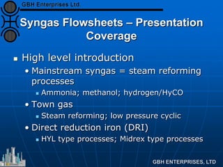
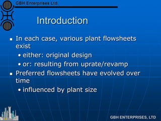
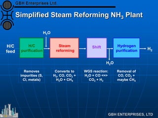
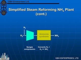
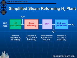
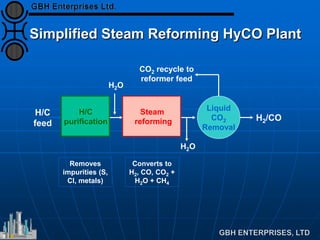
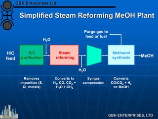
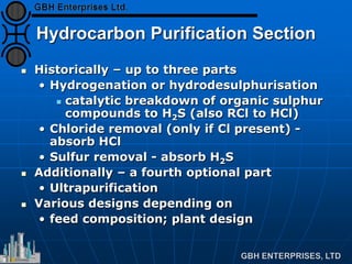
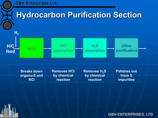
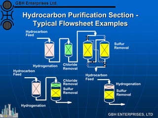
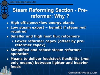
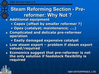
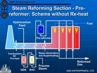
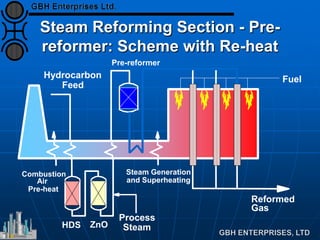


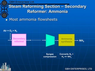
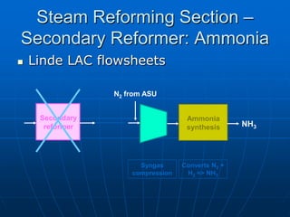
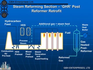
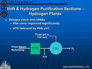
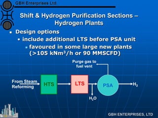
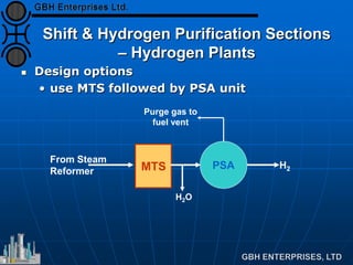


The document provides an overview of syngas plant flowsheet options, detailing various steam reforming processes used for ammonia, methanol, hydrogen, and town gas production. It discusses the evolution of preferred flowsheets, hydrocarbon purification, and the design of reformers, emphasizing key components like pre-reformers, secondary reformers, and purification techniques. The text concludes by highlighting the importance of understanding the complexities and variations in syngas flowsheet designs across different plant configurations.


