Download as PDF, PPTX
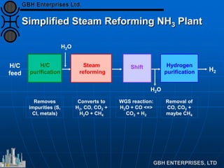
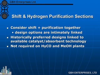
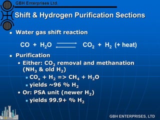
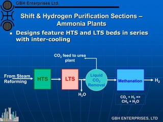
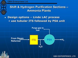
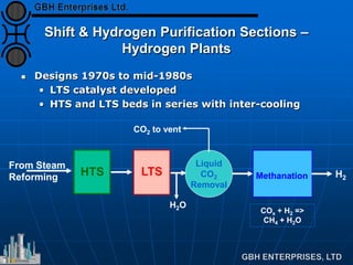
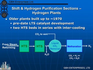
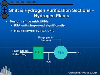
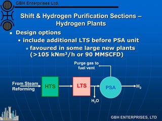
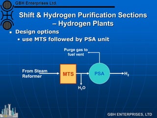


The document discusses different designs for the water gas shift and hydrogen purification sections of steam reforming plants. It describes the water gas shift reaction that converts carbon monoxide and water to carbon dioxide and hydrogen. It outlines designs using high-temperature shift catalyst followed by methanation or pressure swing adsorption to purify the hydrogen for ammonia and hydrogen plants. Newer hydrogen plant designs favor using a high-temperature shift catalyst followed directly by a pressure swing adsorption unit to produce 99.9% pure hydrogen.


![Capital Projects Assessment [Infographic]](https://cdn.slidesharecdn.com/ss_thumbnails/capitalprojectsassessment-130814143908-phpapp01-thumbnail.jpg?width=640&height=640&fit=bounds)


