Download as PDF, PPTX


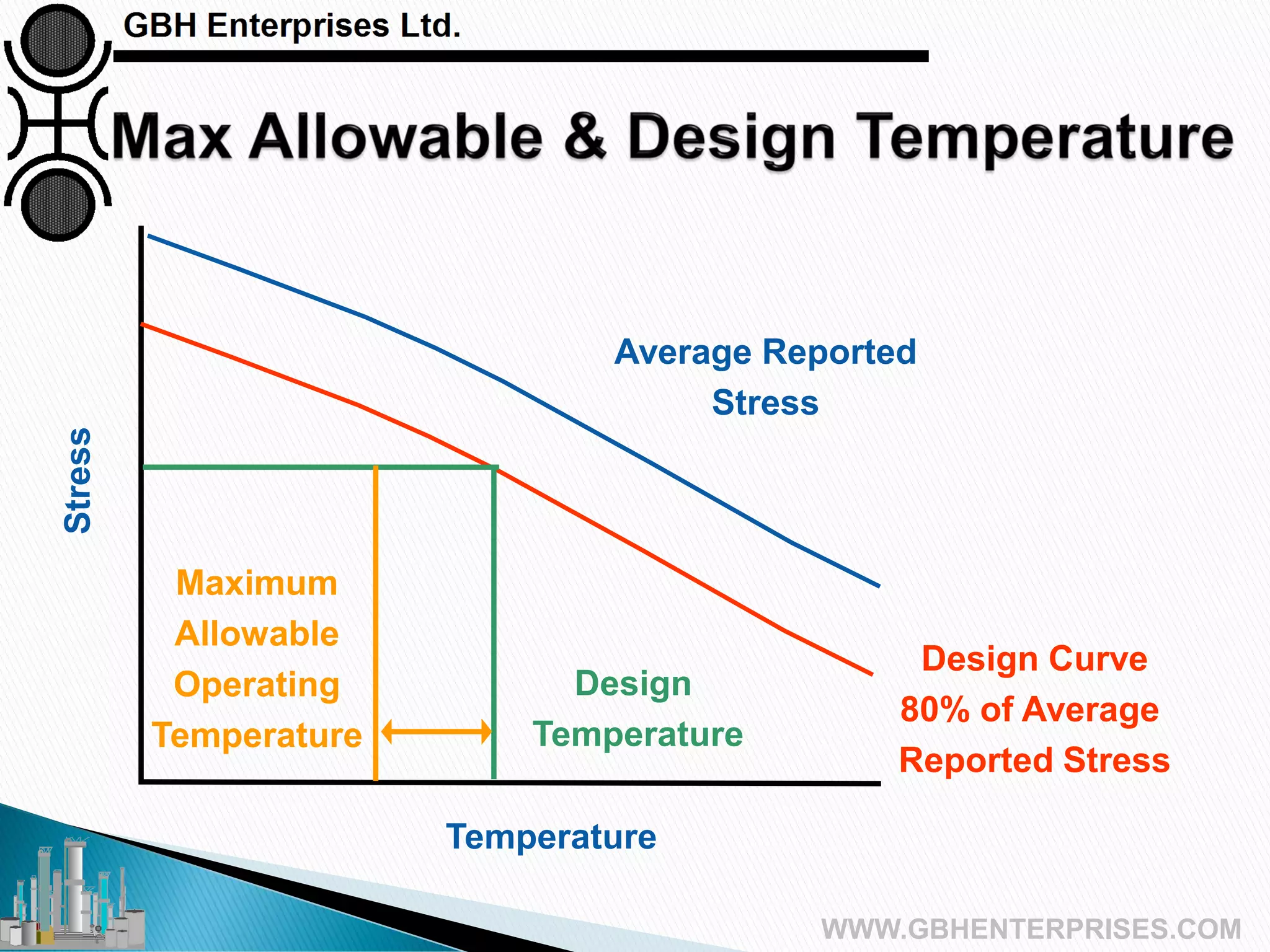


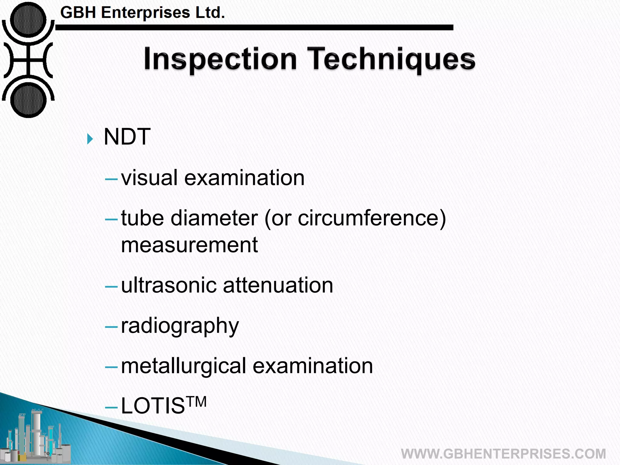


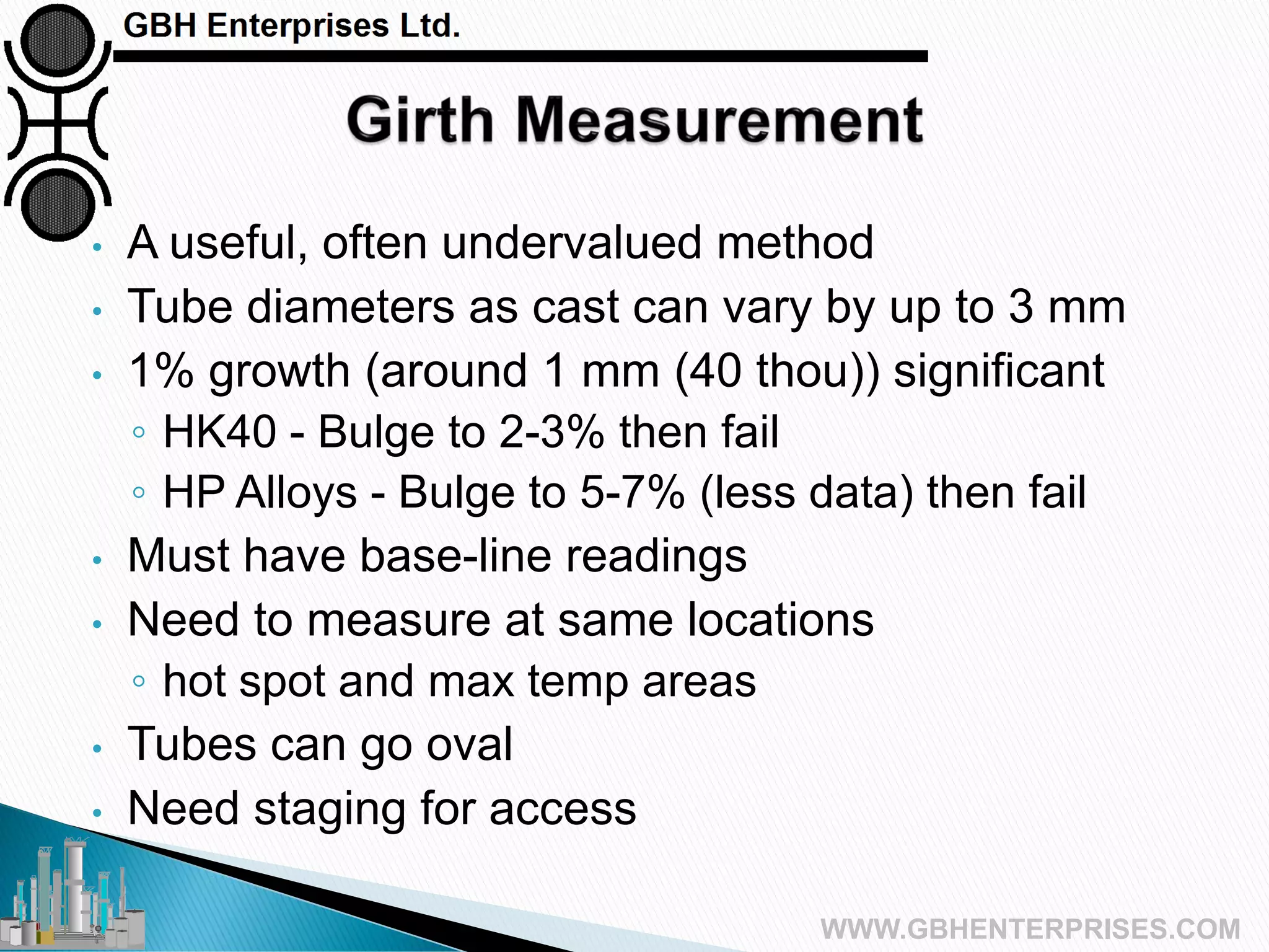


This presentation covers steam reforming tube design, focusing on principles, manufacturing, failure mechanisms, and inspection techniques. It emphasizes the importance of the Larson-Miller parameter for predicting material performance at varying temperatures and stresses, and discusses advancements in tube materials and welding techniques. Additionally, it outlines various inspection methods, including non-destructive testing, to assess tube integrity and life expectancy.


![Capital Projects Assessment [Infographic]](https://cdn.slidesharecdn.com/ss_thumbnails/capitalprojectsassessment-130814143908-phpapp01-thumbnail.jpg?width=640&height=640&fit=bounds)


