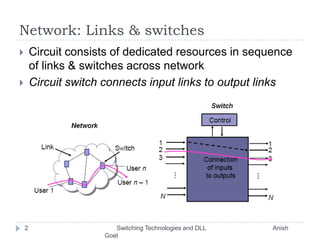
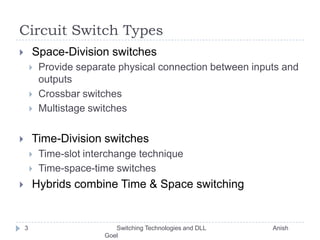
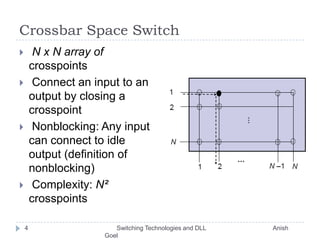
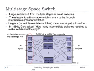
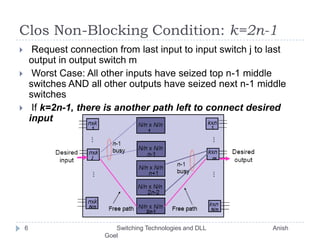
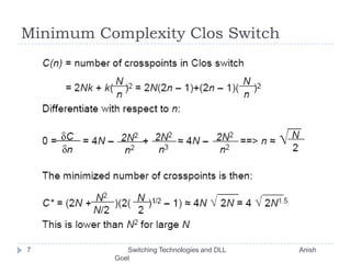
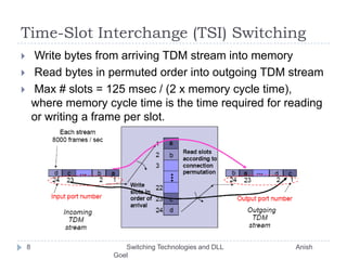
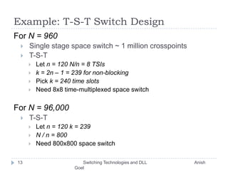
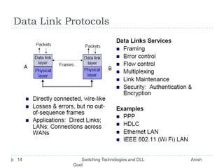
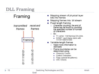
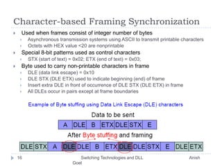
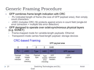
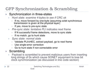
Switching Technologies					  &				Data Link LayerProf. Anish Goel
Network: Links & switchesCircuit consists of dedicated resources in sequence of links & switches across networkCircuit switch connects input links to output links2       Switching Technologies and DLL                                       Anish Goel
Circuit Switch Types Space-Division switchesProvide separate physical connection between inputs and outputsCrossbar switchesMultistage switches Time-Division switchesTime-slot interchange techniqueTime-space-time switches Hybrids combine Time & Space switching3       Switching Technologies and DLL                                       Anish Goel
Crossbar Space SwitchN x N array of crosspoints Connect an input to an output by closing a crosspointNonblocking: Any input can connect to idle output (definition of nonblocking) Complexity: N² crosspoints4       Switching Technologies and DLL                                       Anish Goel
Multistage Space Switch Large switch built from multiple stages of small switches The n inputs to a first-stage switch share k paths through intermediate crossbar switches  Larger k (more intermediate switches) means more paths to output In 1950s, Clos asked, “How many intermediate switches required to make switch nonblocking?”5       Switching Technologies and DLL                                       Anish Goel
Clos Non-Blocking Condition: k=2n-1 Request connection from last input to input switch j to last output in output switch m Worst Case: All other inputs have seized top n-1 middle switches AND all other outputs have seized next n-1 middle switches If k=2n-1, there is another path left to connect desired input to desired output6       Switching Technologies and DLL                                       Anish Goel
Minimum Complexity Clos Switch7       Switching Technologies and DLL                                       Anish Goel
Time-Slot Interchange (TSI) Switching Write bytes from arriving TDM stream into memory Read bytes in permuted order into outgoing TDM stream Max # slots = 125 msec / (2 x memory cycle time), where memory cycle time is the time required for reading or writing a frame per slot.8       Switching Technologies and DLL                                       Anish Goel
Time-Space-Time Hybrid Switch Use TSI in first & third stage; Use crossbar in middle Replace n input x k output space switch by TSI switch that takes n slot input frame and switches it to k-slot output frame9       Switching Technologies and DLL                                       Anish Goel
Flow of time slots between switches The first slot corresponds to the first output line out of each of the first stage switch. Only one space switch active in each time slot10       Switching Technologies and DLL                                       Anish Goel
Time-Share the Crossbar Switch Interconnection pattern of space switch is reconfigured every time slot Very compact design: fewer lines because of TDM & less space because of time-shared crossbar11       Switching Technologies and DLL                                       Anish Goel
Example: A->2, B->4, C->1, D->312       Switching Technologies and DLL                                       Anish Goel
Example: T-S-T Switch DesignFor N = 960 Single stage space switch ~ 1 million crosspoints T-S-T Let n = 120 N/n = 8 TSIsk = 2n – 1 = 239 for non-blocking Pick k = 240 time slots Need 8x8 time-multiplexed space switchFor N = 96,000 T-S-T Let n = 120 k = 239N / n = 800 Need 800x800 space switch13       Switching Technologies and DLL                                       Anish Goel
Data Link Protocols14       Switching Technologies and DLL                                       Anish Goel
DLL Framing15       Switching Technologies and DLL                                       Anish Goel
Character-based Framing Synchronization Used when frames consist of integer number of bytes Asynchronous transmission systems using ASCII to transmit printable characters Octets with HEX value <20 are nonprintable Special 8-bit patterns used as control characters STX (start of text) = 0x02; ETX (end of text) = 0x03; Byte used to carry non-printable characters in frame DLE (data link escape) = 0x10 DLE STX (DLE ETX) used to indicate beginning (end) of frame Insert extra DLE in front of occurrence of DLE STX (DLE ETX) in frame All DLEs occur in pairs except at frame boundaries16       Switching Technologies and DLL                                       Anish Goel
Framing & Bit Stuffing Frame delineated by flag (01111110) character HDLC uses bit stuffing to prevent occurrence of flag 01111110 inside the frame Transmitter inserts extra 0 after each consecutive five 1s inside the frame Receiver checks for five consecutive 1s17       Switching Technologies and DLL                                       Anish Goel
Example: Bit stuffing & de-stuffing18       Switching Technologies and DLL                                       Anish Goel
Frame & Byte Stuffing PPP uses similar frame structure as HDLC, except Protocol type field Payload contains an integer number of bytes PPP uses the same flag, but uses byte stuffing Problems with PPP byte stuffing Size of frame varies unpredictably due to byte insertion Malicious users can inflate bandwidth by inserting 7D & 7E19       Switching Technologies and DLL                                       Anish Goel
Byte-Stuffing in PPPPPP is character-oriented version of HDLC Flag is 0x7E (01111110) Control escape 0x7D (01111101) Any occurrence of flag or control escape inside of frame is replaced with 0x7D followed byoriginal octet exclusive-ORed with 0x20 (00100000) At the receiver, remove 7D and XOR the next character with 0x2020       Switching Technologies and DLL                                       Anish Goel
Generic Framing Procedure GFP combines frame length indication with CRC PLI indicated length of frame (the size of GFP payload area), then simply count characterscHEC (includes CRC-16) protects against errors in count field (single-bit error correction + multiple bits error detection) GFP designed to operate over octet-synchronous physical layers (e.g. SONET) Frame-mapped mode for variable-length payloads: Ethernet Transparent mode carries fixed-length payload: storage devices21       Switching Technologies and DLL                                       Anish Goel
GFP Synchronization & Scrambling Synchronization in three-statesHunt state: examine 4-bytes to see if CRC ok If no, move forward by one-byte (assuming octet synchronous transmission is given at the physical layer). If yes, move to pre-sync statePre-sync state: tentative PLI indicates next frame If N successful frame detections, move to sync state If no match, go to hunt stateSync state: normal state Validate PLI/cHEC, extract payload, go to next frame Use single-error correction Go to hunt state if non-correctable error Scrambling Payload is scrambled to prevent malicious users from inserting long strings of 0s which cause SONET equipment to lose bit clock synchronization (as discussed in line code section)22       Switching Technologies and DLL                                       Anish Goel

Switching Tech And Data Link

  • 1.
    Switching Technologies & Data Link LayerProf. Anish Goel
  • 2.
    Network: Links &switchesCircuit consists of dedicated resources in sequence of links & switches across networkCircuit switch connects input links to output links2 Switching Technologies and DLL Anish Goel
  • 3.
    Circuit Switch TypesSpace-Division switchesProvide separate physical connection between inputs and outputsCrossbar switchesMultistage switches Time-Division switchesTime-slot interchange techniqueTime-space-time switches Hybrids combine Time & Space switching3 Switching Technologies and DLL Anish Goel
  • 4.
    Crossbar Space SwitchNx N array of crosspoints Connect an input to an output by closing a crosspointNonblocking: Any input can connect to idle output (definition of nonblocking) Complexity: N² crosspoints4 Switching Technologies and DLL Anish Goel
  • 5.
    Multistage Space SwitchLarge switch built from multiple stages of small switches The n inputs to a first-stage switch share k paths through intermediate crossbar switches Larger k (more intermediate switches) means more paths to output In 1950s, Clos asked, “How many intermediate switches required to make switch nonblocking?”5 Switching Technologies and DLL Anish Goel
  • 6.
    Clos Non-Blocking Condition:k=2n-1 Request connection from last input to input switch j to last output in output switch m Worst Case: All other inputs have seized top n-1 middle switches AND all other outputs have seized next n-1 middle switches If k=2n-1, there is another path left to connect desired input to desired output6 Switching Technologies and DLL Anish Goel
  • 7.
    Minimum Complexity ClosSwitch7 Switching Technologies and DLL Anish Goel
  • 8.
    Time-Slot Interchange (TSI)Switching Write bytes from arriving TDM stream into memory Read bytes in permuted order into outgoing TDM stream Max # slots = 125 msec / (2 x memory cycle time), where memory cycle time is the time required for reading or writing a frame per slot.8 Switching Technologies and DLL Anish Goel
  • 9.
    Time-Space-Time Hybrid SwitchUse TSI in first & third stage; Use crossbar in middle Replace n input x k output space switch by TSI switch that takes n slot input frame and switches it to k-slot output frame9 Switching Technologies and DLL Anish Goel
  • 10.
    Flow of timeslots between switches The first slot corresponds to the first output line out of each of the first stage switch. Only one space switch active in each time slot10 Switching Technologies and DLL Anish Goel
  • 11.
    Time-Share the CrossbarSwitch Interconnection pattern of space switch is reconfigured every time slot Very compact design: fewer lines because of TDM & less space because of time-shared crossbar11 Switching Technologies and DLL Anish Goel
  • 12.
    Example: A->2, B->4,C->1, D->312 Switching Technologies and DLL Anish Goel
  • 13.
    Example: T-S-T SwitchDesignFor N = 960 Single stage space switch ~ 1 million crosspoints T-S-T Let n = 120 N/n = 8 TSIsk = 2n – 1 = 239 for non-blocking Pick k = 240 time slots Need 8x8 time-multiplexed space switchFor N = 96,000 T-S-T Let n = 120 k = 239N / n = 800 Need 800x800 space switch13 Switching Technologies and DLL Anish Goel
  • 14.
    Data Link Protocols14 Switching Technologies and DLL Anish Goel
  • 15.
    DLL Framing15 Switching Technologies and DLL Anish Goel
  • 16.
    Character-based Framing SynchronizationUsed when frames consist of integer number of bytes Asynchronous transmission systems using ASCII to transmit printable characters Octets with HEX value <20 are nonprintable Special 8-bit patterns used as control characters STX (start of text) = 0x02; ETX (end of text) = 0x03; Byte used to carry non-printable characters in frame DLE (data link escape) = 0x10 DLE STX (DLE ETX) used to indicate beginning (end) of frame Insert extra DLE in front of occurrence of DLE STX (DLE ETX) in frame All DLEs occur in pairs except at frame boundaries16 Switching Technologies and DLL Anish Goel
  • 17.
    Framing & BitStuffing Frame delineated by flag (01111110) character HDLC uses bit stuffing to prevent occurrence of flag 01111110 inside the frame Transmitter inserts extra 0 after each consecutive five 1s inside the frame Receiver checks for five consecutive 1s17 Switching Technologies and DLL Anish Goel
  • 18.
    Example: Bit stuffing& de-stuffing18 Switching Technologies and DLL Anish Goel
  • 19.
    Frame & ByteStuffing PPP uses similar frame structure as HDLC, except Protocol type field Payload contains an integer number of bytes PPP uses the same flag, but uses byte stuffing Problems with PPP byte stuffing Size of frame varies unpredictably due to byte insertion Malicious users can inflate bandwidth by inserting 7D & 7E19 Switching Technologies and DLL Anish Goel
  • 20.
    Byte-Stuffing in PPPPPPis character-oriented version of HDLC Flag is 0x7E (01111110) Control escape 0x7D (01111101) Any occurrence of flag or control escape inside of frame is replaced with 0x7D followed byoriginal octet exclusive-ORed with 0x20 (00100000) At the receiver, remove 7D and XOR the next character with 0x2020 Switching Technologies and DLL Anish Goel
  • 21.
    Generic Framing ProcedureGFP combines frame length indication with CRC PLI indicated length of frame (the size of GFP payload area), then simply count characterscHEC (includes CRC-16) protects against errors in count field (single-bit error correction + multiple bits error detection) GFP designed to operate over octet-synchronous physical layers (e.g. SONET) Frame-mapped mode for variable-length payloads: Ethernet Transparent mode carries fixed-length payload: storage devices21 Switching Technologies and DLL Anish Goel
  • 22.
    GFP Synchronization &Scrambling Synchronization in three-statesHunt state: examine 4-bytes to see if CRC ok If no, move forward by one-byte (assuming octet synchronous transmission is given at the physical layer). If yes, move to pre-sync statePre-sync state: tentative PLI indicates next frame If N successful frame detections, move to sync state If no match, go to hunt stateSync state: normal state Validate PLI/cHEC, extract payload, go to next frame Use single-error correction Go to hunt state if non-correctable error Scrambling Payload is scrambled to prevent malicious users from inserting long strings of 0s which cause SONET equipment to lose bit clock synchronization (as discussed in line code section)22 Switching Technologies and DLL Anish Goel