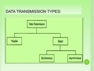
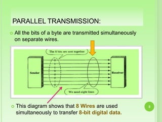
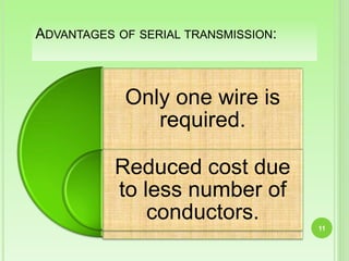
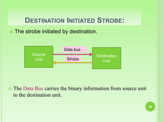
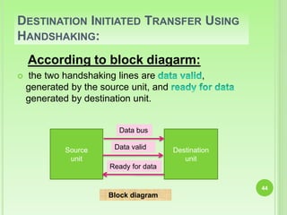
The document discusses different methods of data transmission between digital devices. It describes parallel transmission where all bits are transmitted simultaneously on separate wires, allowing for faster transmission but requiring more wires. Serial transmission transmits bits one after the other on a single wire, requiring fewer wires but slower transmission. Synchronous transmission uses a common clock while asynchronous transmission uses start and stop bits between bytes. The document also discusses transmission modes like simplex, half-duplex, and full-duplex, and methods for asynchronous transmission including strobe control and handshaking.
Synchronous and Asynchronous TransmissionAdeel Rasheed
Synchronous communication requires that the transmitting and receiving devices have synchronized clocks running at the same rate to allow data to flow continuously in blocks or frames in a full duplex mode, making it efficient and reliable for transferring large amounts of data, as is used for chat rooms, video calls, and phone conversations. In asynchronous transmission, data is sent intermittently without an external clock, flowing in a half duplex mode one byte at a time, generally with 8 data bits plus a start and stop bit, and is used for letters, emails, television, and radio.
A digital signal is a sequence of discrete, discontinuous voltage pulses. Each pulse is a signal element. Binary data '0' and '1' are transmitted over digital channel by encoding each data bit into signal elements. Encoding scheme is mapping from data bits to signal elements. Line coding is done to prevent DC wandering and loss of synchronisation on long strings of '0' and '1'. It may give some amount of error detection as in AMT.
This document discusses different types of data transfer modes between I/O devices and memory, including programmed I/O, interrupt-driven I/O, and direct memory access (DMA). It explains that DMA allows I/O devices to access memory directly without CPU intervention by using a DMA controller. The basic operations of DMA include the DMA controller gaining control of the system bus, transferring data directly between memory and I/O devices by updating address and count registers, and then relinquishing control back to the CPU. Different DMA transfer techniques like byte stealing, burst, and continuous modes are also covered.
1) Asynchronous data transfer uses control signals rather than a shared clock to communicate between devices. There are two methods: strobe signals with one control line, and handshaking with two control lines.
2) In strobe signaling, either the source or destination can initiate data transfer by activating a strobe pulse along with data on the data bus. There is no confirmation that the data was received.
3) Handshaking uses two control lines - one for data validity from source to destination, and another for data acceptance from destination to source. This allows each device to operate independently while confirming the data transfer was completed.
This document discusses line coding techniques used for digital data transmission. It begins by explaining the need for line coding due to the discrete and band-limited nature of information being transmitted. Then it covers various line coding techniques including unipolar, polar, bipolar, and Manchester coding. It discusses the properties, advantages, disadvantages and power spectral density of each technique. Finally, it provides a comparison of polar RZ, polar NRZ, AMI and Manchester coding in terms of their transmission of DC components, signaling rate, noise immunity, synchronization capability, bandwidth requirement, and crosstalk.
This document discusses signals and signal propagation in wireless communication networks. It covers several key topics:
1. Signals are the physical representation of data that is transmitted through communication systems. Signal parameters like amplitude, frequency, and phase shift encode the data.
2. Signals propagate through wireless networks differently than through wired networks due to effects like reflection, scattering, diffraction and multipath propagation. This results in delayed and attenuated signals arriving at the receiver.
3. Techniques like TDMA, CDMA and multiple access protocols are used to allow multiple users to share the same wireless medium and communicate simultaneously. Fixed and dynamic channel allocation schemes are discussed.
Cache memory is a small, fast memory located between the CPU and main memory. It stores copies of frequently used instructions and data to accelerate access and improve performance. There are different mapping techniques for cache including direct mapping, associative mapping, and set associative mapping. When the cache is full, replacement algorithms like LRU and FIFO are used to determine which content to remove. The cache can write to main memory using either a write-through or write-back policy.
Data Communication & Computer Networks : Serial and parellel transmissionDr Rajiv Srivastava
The document discusses serial and parallel transmission. It provides details on synchronous and asynchronous serial transmission. Asynchronous transmission transmits bytes individually with start and stop bits between each byte, while synchronous transmission transmits blocks of bytes continuously at high speed using synchronization patterns. Asynchronous transmission is simpler but slower, while synchronous transmission is faster but requires accurate clock synchronization between transmitter and receiver. The document compares the two serial transmission methods and also discusses their advantages and disadvantages.
The document discusses direct memory access (DMA) and DMA controllers. It explains that DMA allows hardware subsystems like disk drives and graphics cards to access main memory independently of the CPU. This is useful because it allows data transfers to occur in parallel with other CPU operations, improving overall system performance. A DMA controller generates memory addresses and initiates read/write cycles. It has registers that specify the I/O port, transfer direction, and number of bytes to transfer per burst. DMA controllers use different transfer modes like burst, cycle stealing, and transparent to move blocks of data efficiently between peripheral devices and memory.
DMA data transfer involves transferring large amounts of data between I/O devices and memory without involving the CPU. There are three types of DMA transfer techniques: burst/block transfer DMA transfers all data at once, cycle steal/single-byte transfer DMA transfers one byte at a time alternating with the CPU, and transparent/hidden DMA transfers data during times when the CPU floats the buses so it is transparent to the CPU.
UDP is a connectionless transport layer protocol that runs over IP. It provides an unreliable best-effort service where packets may be lost, delivered out of order, or duplicated. UDP has a small 8-byte header and is lightweight, with no connection establishment or guarantee of delivery. This makes it fast and low overhead, suitable for real-time applications like streaming media where resending lost packets would cause delay.
Memory mapped I/O and isolated I/O are two methods for interfacing I/O devices with the CPU. With isolated I/O, memory and I/O devices have separate address spaces and control lines, allowing special I/O instructions. With memory mapped I/O, memory and I/O share the same address space and instructions, treating I/O as memory, but reducing available memory addresses. Both methods have advantages like flexibility and speed, but also disadvantages regarding complexity and available address space.
Cache memory is a small, high-speed memory located between the CPU and main memory. It stores copies of frequently used instructions and data from main memory in order to speed up processing. There are multiple levels of cache with L1 cache being the smallest and fastest located directly on the CPU chip. Larger cache levels like L2 and L3 are further from the CPU but can still provide faster access than main memory. The main purpose of cache is to accelerate processing speed while keeping computer costs low.
Michael Flynn proposed a taxonomy in 1966 to classify computer architectures based on the number of instruction streams and data streams. The four classifications are: SISD (single instruction, single data stream), SIMD (single instruction, multiple data streams), MISD (multiple instructions, single data stream), and MIMD (multiple instructions, multiple data streams). SISD corresponds to the traditional von Neumann architecture, SIMD is used for array processing, MIMD describes most modern parallel computers, and MISD has never been implemented.
Direct Memory Access (DMA) allows certain hardware subsystems to access main system memory independently of the CPU. DMA controllers temporarily borrow the address, data, and control buses from the microprocessor to transfer data directly between an I/O port and memory locations. This allows fast transfer of data to and from devices while the CPU performs other tasks, improving overall system performance. DMA transfers can occur via block transfers where the DMA controller controls the bus for an extended period, or via cycle stealing where it uses the bus for one transfer then returns control to the CPU.
Channelization is a multiple-access method in which the available bandwidth of a link is shared in time, frequency, or through code, between different stations. The three channelization protocols are FDMA, TDMA, and CDMA
PROGRAMMABLE KEYBOARD AND DISPLAY INTERFACE(8279).pptxSanjayV73
The 8279 is a programmable keyboard/display controller chip that interfaces a keyboard and display with a microprocessor. It has sections to interface with the CPU, scan the keyboard matrix and display, and handle keyboard and display functions. The 8279 supports keyboards up to 64 keys and displays up to 16 digits. It operates in different modes and has registers to control the keyboard, display, and transfer data between the CPU and peripheral devices.
This document discusses various types of micro operations that can be performed at the digital component level in digital systems. It describes arithmetic micro operations like addition, subtraction, increment, decrement, and shift. It provides examples of how these operations are represented and implemented using registers and binary adders or subtractors. It also discusses logic micro operations and shift micro operations, providing examples of each type.
This document discusses asynchronous data transfer between independent units. It describes two methods for asynchronous transfer - strobe control and handshaking. Strobe control uses a single control line to time each transfer, while handshaking introduces a second control signal to provide confirmation between units. Specifically, it details the handshaking process, which involves control signals like "data valid" and "data accepted" or "ready for data" to coordinate placing data on the bus and accepting data between a source and destination unit.
The document discusses pipeline hazards including structural, data, and control hazards. It provides details on how each hazard can occur in a 5-stage pipeline and techniques to resolve them, including forwarding, stalling, and compiler scheduling. Data hazards are classified as RAW, WAW, and WAR. Control hazards from branches are reduced by computing the branch target and outcome earlier in the ID phase to minimize stalls.
Direct memory access (DMA) allows certain hardware subsystems to access computer memory independently of the central processing unit (CPU). During DMA transfer, the CPU is idle while an I/O device reads from or writes directly to memory using a DMA controller. This improves data transfer speeds as the CPU does not need to manage each memory access and can perform other tasks. DMA is useful when CPU cannot keep up with data transfer speeds or needs to work while waiting for a slow I/O operation to complete.
Delta modulation is an analog-to-digital conversion technique used to transfer data. It works by comparing an input signal to a reference signal and encoding the difference into a digital bitstream. A delta modulation system consists of a modulator that converts an analog signal to digital, and a demodulator that converts the digital signal back to analog. Delta modulation is simpler than pulse code modulation but can achieve high signal-to-noise ratios and variable bandwidth. However, it is limited by slope overload when signals change rapidly.
(Ref : Computer System Architecture by Morris Mano 3rd edition) : Microprogrammed Control unit, micro instructions, micro operations, symbolic and binary microprogram.
This document discusses different types of data transmission between digital devices. It describes parallel transmission, where all bits are transmitted simultaneously on separate wires, and serial transmission, where bits are transmitted sequentially on a single wire. The document also discusses synchronous transmission, which uses a common clock, and asynchronous transmission, which uses start and stop bits. Finally, it covers strobe control and handshaking methods for asynchronous transmission, where handshaking provides confirmation that data was received.
The input-output interface synchronizes the operating speed of the CPU with I/O devices, selects the appropriate device, and provides control and timing signals. It can buffer data through the data bus and contains error detectors. The interface also converts between serial and parallel data and between digital and analog signals. Asynchronous data transfer occurs between independent units like the CPU and I/O interface that use separate clocks. This requires control signals to indicate when data is sent. The strobe control method uses a single strobe line controlled by the source or destination unit. The handshaking method introduces two control lines - one for valid data from source to destination and another for acceptance from destination to source.
The document discusses input-output (I/O) interfaces in computers. It provides details on:
1. I/O interfaces act as a hardware circuit between the CPU and I/O devices to synchronize data transfer.
2. There are differences between peripheral devices and CPUs in operation, data formats, and speeds that require special hardware (I/O interfaces) to resolve.
3. I/O interfaces contain registers to buffer input and output data and status information during transfers between CPUs and peripheral devices like keyboards, printers, and monitors.
This document discusses asynchronous data transfer methods between independent units without a common clock. It describes two main methods: strobe pulse and handshaking. Strobe pulse uses a single control line to time transfers but the transmitting unit has no confirmation the data was received. Handshaking adds a second control signal so units can confirm receipt. It then discusses asynchronous serial transfer which transmits bits sequentially using start, data, and stop bits to identify characters without a shared clock. First-in first-out (FIFO) buffers are also summarized as allowing input and output of data at different rates while preserving order.
This document discusses asynchronous data transfer between a CPU and I/O device. It describes two common methods - strobe control and handshaking. Strobe control uses a single control signal to indicate when valid data is available on the data bus. This can be source-initiated, where the source activates the strobe, or destination-initiated, where the destination activates the strobe to request data. Handshaking accompanies each data transfer with control signals from both the sender and receiver to acknowledge the data.
The document discusses synchronous and asynchronous data transfer methods. Synchronous transfer uses a common clock between the CPU and I/O interface, while asynchronous transfer has independent clocks. Asynchronous methods include strobe control using a single strobe signal, and handshaking using two control signals - one from sender to receiver and one from receiver to sender to acknowledge receipt. Handshaking ensures both units know when data is available and received.
Congratulations! #You have earned 30 reward points for the first Fonepay transaction. Your balance is 30. Redeem points######################################################### have earned 30 reward points for the first Fonepay transaction. Your balance is 30. Redeem points using Fonepay app onelink.to/tn3ze7Congratulations! You have earned 30 reward points for the first Fonepay transaction. Your balance is 30. Redeem points using Fonepay app onelink.to/tn3ze7Congratulations! You have earned 30 reward points for the first Fonepay transaction. Your balance is 30. Redeem points using Fonepay app onelink.to/tn3ze7Congratulations! You have earned 30 reward points for the first Fonepay transaction. Your balance is 30. Redeem points using Fonepay app onelink.to/tn3ze7Congratulations! You have earned 30 reward points for the first Fonepay transaction. Your balance is 30. Redeem points using Fonepay app onelink.to/tn3ze7Congratulations! You have earned 30 reward points for the first Fonepay transaction. Your balance is 30. Redeem points using Fonepay app onelink.to/tn3ze7Congratulations! You have earned 30 reward points for the first Fonepay transaction. Your balance is 30. Redeem points using Fonepay app onelink.to/tn3ze7Congratulations! You have earned 30 reward points for the first Fonepay transaction. Your balance is 30. Redeem points using Fonepay app onelink.to/tn3ze7Congratulations! You have earned 30 reward points for the first Fonepay transaction. Your balance is 30. Redeem points using Fonepay app onelink.to/tn3ze7Congratulations! You have earned 30 reward points for the first Fonepay transaction. Your balance is 30. Redeem points using Fonepay app onelink.to/tn3ze7Congratulations! You have earned 30 reward points for the first Fonepay transaction. Your balance is 30. Redeem points using Fonepay app onelink.to/tn3ze7Congratulations! You have earned 30 reward points for the first Fonepay transaction. Your balance is 30. Redeem points using Fonepay app onelink.to/tn3ze7Congratulations! You have earned 30 reward points for the first Fonepay transaction. Your balance is 30. Redeem points using Fonepay app onelink.to/tn3ze7Congratulations! You have earned 30 reward points for the first Fonepay transaction. Your balance is 30. Redeem points using Fonepay app №########################################################################################################################################################################################################################№##################################№#################################################################################onelink.to/tn3ze7Congratulations! You have earned 30 reward points for the first Fonepay transaction. Your balance is 30. Redeem points using Fonepay app ######onelink.to/tn3z#####################№№#########################e7Congratulations! You have earned 30 reward points for the first Fonepay transaction. Your balance is 30. Redeem p#################################
This document discusses asynchronous and synchronous communication. Asynchronous communication transmits data intermittently without an external clock, with timing encoded in the symbols. It is used for variable bit rate applications like file transfers and email. Synchronous communication transmits data in a steady stream at a constant rate, requiring synchronized clocks, but allows more data transfer. It is used for real-time applications like telephone calls. Both methods have advantages and disadvantages related to overhead, speed and clock synchronization.
The document discusses the 8251A USART chip, which can be used for both asynchronous and synchronous serial communication. It describes the basic components and functions of the 8251A chip, including its transmitter and receiver sections that convert parallel to serial data and vice versa. The document also explains the differences between asynchronous and synchronous serial communication and covers various control signals and registers used by the 8251A for data transfer and interfacing with external devices like modems.
This document discusses different modes of data transmission between digital devices. It describes parallel transmission, which transfers all data bits simultaneously over separate lines and is faster but more costly than serial transmission. Serial transmission sends each data bit in sequence over a single line, making it less costly but slower. Transmission can be synchronous, sending multiple bytes at once without start/stop bits, or asynchronous, sending one byte at a time with start/stop bits. Modes of transmission include simplex (one-way), half duplex (one-way at a time), and full duplex (two-way simultaneous).
The document discusses input/output (I/O) organization in computers. It covers various topics related to I/O including I/O interfaces, asynchronous and synchronous data transfer, and different modes of data transfer like programmed I/O and direct memory access. It describes how I/O devices connect to the computer and how interface modules resolve differences in data formats and transfer rates between I/O devices and the CPU. It also discusses I/O buses and different methods of communication between CPU, memory, and I/O including separate I/O and memory buses, isolated I/O using separate control lines, and memory mapped I/O.
The document discusses asynchronous and synchronous data transfer using the 8251A USART chip. It describes the basics of serial communication including synchronous vs asynchronous transmission. It provides details on the sections and functioning of the 8251A chip, including its transmitter, receiver, and modem control sections. The pin diagram and functions of the pins are also explained.
The document discusses asynchronous and synchronous serial communication using the 8251A USART chip. It describes the basics of serial communication including synchronous vs asynchronous transmission. It provides details on the components and functioning of the 8251A USART chip, including its transmitter, receiver, control logic and modem control sections. The chip allows for full-duplex serial communication and can operate in both synchronous and asynchronous modes. It converts parallel data from the microprocessor to serial data for transmission and vice versa on reception.
The document discusses various aspects of I/O organization in a computer system. It describes the input-output interface that provides a method for transferring information between internal storage and external I/O devices. It discusses asynchronous data transfer techniques like strobe control and handshaking. It also covers asynchronous serial transmission, different modes of data transfer like programmed I/O, interrupt-initiated I/O, and direct memory access (DMA).
This document provides an introduction to data communication and transmission. It defines data and describes how data is communicated from a source to a receiver. It explains the components of a data communication system including the message, sender, receiver, medium, and protocols. Protocols are defined as sets of rules that govern communication and their functions like data sequencing, routing, formatting, flow control, error control, and security are described. The modes of data transmission - simplex, half-duplex, and full-duplex - are defined. Serial and parallel transmission methods are also explained along with asynchronous and synchronous serial transmission types.
Total slides: 73
Universal Asynchronous Receiver Transmitter (UART)
Introduction to Serial Communication
Types of Transmission
Simplex Communication
Duplex Communication
Half Duplex Communication
Full Duplex Communication
Methods of Serial data Transmission
Synchronous serial data transfer
Asynchronous serial data transfer
Differences Synchronous Asynchronous
Data Transfer Rate
Calculation of Baud Rate
SCON Register
SBUF Register
Writing to the Serial port
Reading the Serial port
PCON Register
Programming of transmission byte serially
Programming of reception of byte serially
Examples
This document discusses different modes of data transmission including parallel, serial, synchronous, and asynchronous transmission. It provides details on:
1) Parallel transmission involves sending multiple bits simultaneously over separate wires, while serial transmission sends one bit at a time over a single wire.
2) Asynchronous transmission uses start and stop bits to delineate individual bytes since there is no external clock synchronization.
3) Synchronous transmission frames multiple bytes together and relies on an external clock for synchronization between transmitter and receiver.
Serial transmission reduces costs compared to parallel transmission by sending data one bit at a time over a single communication channel rather than multiple bits simultaneously over multiple channels. There are two types of serial transmission: synchronous uses a common clock and eliminates wasted bits while asynchronous uses start and stop bits but is slower. Shift registers can be used to serially input and output data from a data word non-destructively using control lines to indicate writing versus reading cycles.
CS304PC:Computer Organization and Architecture Session 25 Asynchronous data t...Asst.prof M.Gokilavani
This document contains the summary of a session on computer organization and architecture. It discusses asynchronous data transfer methods like strobe control and handshaking. Strobe control uses a single strobe line to time data transfers, while handshaking uses two control signals - one from the source to indicate valid data and another from the destination to acknowledge receipt. It explains source initiated and destination initiated handshaking transfers through state diagrams. The next session will cover modes of transfer.
This document discusses two methods for asynchronous data transfer: strobe pulse and handshaking. Strobe pulse uses a single control line to time each data transfer, initiated either by the source or destination unit. Handshaking uses two control signals - one from the source to indicate valid data, and another from the destination to acknowledge receipt. It allows arbitrary delays between units operating at different rates. Asynchronous serial transfer sends each data bit sequentially over a single line, with start and stop bits framing each character.
Similar to DATA TRANSMISSION, Synchronous & Asynchronous Data Transfer (20)
ESPP presentation to EU Waste Water Network, 4th June 2024 “EU policies driving nutrient removal and recycling
and the revised UWWTD (Urban Waste Water Treatment Directive)”
Unlocking the mysteries of reproduction: Exploring fecundity and gonadosomati...AbdullaAlAsif1
The pygmy halfbeak Dermogenys colletei, is known for its viviparous nature, this presents an intriguing case of relatively low fecundity, raising questions about potential compensatory reproductive strategies employed by this species. Our study delves into the examination of fecundity and the Gonadosomatic Index (GSI) in the Pygmy Halfbeak, D. colletei (Meisner, 2001), an intriguing viviparous fish indigenous to Sarawak, Borneo. We hypothesize that the Pygmy halfbeak, D. colletei, may exhibit unique reproductive adaptations to offset its low fecundity, thus enhancing its survival and fitness. To address this, we conducted a comprehensive study utilizing 28 mature female specimens of D. colletei, carefully measuring fecundity and GSI to shed light on the reproductive adaptations of this species. Our findings reveal that D. colletei indeed exhibits low fecundity, with a mean of 16.76 ± 2.01, and a mean GSI of 12.83 ± 1.27, providing crucial insights into the reproductive mechanisms at play in this species. These results underscore the existence of unique reproductive strategies in D. colletei, enabling its adaptation and persistence in Borneo's diverse aquatic ecosystems, and call for further ecological research to elucidate these mechanisms. This study lends to a better understanding of viviparous fish in Borneo and contributes to the broader field of aquatic ecology, enhancing our knowledge of species adaptations to unique ecological challenges.
Nucleophilic Addition of carbonyl compounds.pptxSSR02
Nucleophilic addition is the most important reaction of carbonyls. Not just aldehydes and ketones, but also carboxylic acid derivatives in general.
Carbonyls undergo addition reactions with a large range of nucleophiles.
Comparing the relative basicity of the nucleophile and the product is extremely helpful in determining how reversible the addition reaction is. Reactions with Grignards and hydrides are irreversible. Reactions with weak bases like halides and carboxylates generally don’t happen.
Electronic effects (inductive effects, electron donation) have a large impact on reactivity.
Large groups adjacent to the carbonyl will slow the rate of reaction.
Neutral nucleophiles can also add to carbonyls, although their additions are generally slower and more reversible. Acid catalysis is sometimes employed to increase the rate of addition.
Current Ms word generated power point presentation covers major details about the micronuclei test. It's significance and assays to conduct it. It is used to detect the micronuclei formation inside the cells of nearly every multicellular organism. It's formation takes place during chromosomal sepration at metaphase.
The ability to recreate computational results with minimal effort and actionable metrics provides a solid foundation for scientific research and software development. When people can replicate an analysis at the touch of a button using open-source software, open data, and methods to assess and compare proposals, it significantly eases verification of results, engagement with a diverse range of contributors, and progress. However, we have yet to fully achieve this; there are still many sociotechnical frictions.
Inspired by David Donoho's vision, this talk aims to revisit the three crucial pillars of frictionless reproducibility (data sharing, code sharing, and competitive challenges) with the perspective of deep software variability.
Our observation is that multiple layers — hardware, operating systems, third-party libraries, software versions, input data, compile-time options, and parameters — are subject to variability that exacerbates frictions but is also essential for achieving robust, generalizable results and fostering innovation. I will first review the literature, providing evidence of how the complex variability interactions across these layers affect qualitative and quantitative software properties, thereby complicating the reproduction and replication of scientific studies in various fields.
I will then present some software engineering and AI techniques that can support the strategic exploration of variability spaces. These include the use of abstractions and models (e.g., feature models), sampling strategies (e.g., uniform, random), cost-effective measurements (e.g., incremental build of software configurations), and dimensionality reduction methods (e.g., transfer learning, feature selection, software debloating).
I will finally argue that deep variability is both the problem and solution of frictionless reproducibility, calling the software science community to develop new methods and tools to manage variability and foster reproducibility in software systems.
Exposé invité Journées Nationales du GDR GPL 2024
Or: Beyond linear.
Abstract: Equivariant neural networks are neural networks that incorporate symmetries. The nonlinear activation functions in these networks result in interesting nonlinear equivariant maps between simple representations, and motivate the key player of this talk: piecewise linear representation theory.
Disclaimer: No one is perfect, so please mind that there might be mistakes and typos.
dtubbenhauer@gmail.com
Corrected slides: dtubbenhauer.com/talks.html
Remote Sensing and Computational, Evolutionary, Supercomputing, and Intellige...University of Maribor
Slides from talk:
Aleš Zamuda: Remote Sensing and Computational, Evolutionary, Supercomputing, and Intelligent Systems.
11th International Conference on Electrical, Electronics and Computer Engineering (IcETRAN), Niš, 3-6 June 2024
Inter-Society Networking Panel GRSS/MTT-S/CIS Panel Session: Promoting Connection and Cooperation
https://www.etran.rs/2024/en/home-english/
ESR spectroscopy in liquid food and beverages.pptxPRIYANKA PATEL
With increasing population, people need to rely on packaged food stuffs. Packaging of food materials requires the preservation of food. There are various methods for the treatment of food to preserve them and irradiation treatment of food is one of them. It is the most common and the most harmless method for the food preservation as it does not alter the necessary micronutrients of food materials. Although irradiated food doesn’t cause any harm to the human health but still the quality assessment of food is required to provide consumers with necessary information about the food. ESR spectroscopy is the most sophisticated way to investigate the quality of the food and the free radicals induced during the processing of the food. ESR spin trapping technique is useful for the detection of highly unstable radicals in the food. The antioxidant capability of liquid food and beverages in mainly performed by spin trapping technique.
The binding of cosmological structures by massless topological defectsSérgio Sacani
Assuming spherical symmetry and weak field, it is shown that if one solves the Poisson equation or the Einstein field
equations sourced by a topological defect, i.e. a singularity of a very specific form, the result is a localized gravitational
field capable of driving flat rotation (i.e. Keplerian circular orbits at a constant speed for all radii) of test masses on a thin
spherical shell without any underlying mass. Moreover, a large-scale structure which exploits this solution by assembling
concentrically a number of such topological defects can establish a flat stellar or galactic rotation curve, and can also deflect
light in the same manner as an equipotential (isothermal) sphere. Thus, the need for dark matter or modified gravity theory is
mitigated, at least in part.
Comparing Evolved Extractive Text Summary Scores of Bidirectional Encoder Rep...University of Maribor
Slides from:
11th International Conference on Electrical, Electronics and Computer Engineering (IcETRAN), Niš, 3-6 June 2024
Track: Artificial Intelligence
https://www.etran.rs/2024/en/home-english/
5. PARALLEL TRANSMISSION:
All the bits of a byte are transmitted simultaneously
on separate wires.
5 This diagram shows that 8 Wires are used
simultaneously to transfer 8-bit digital data.
6. PARALLEL TRANSMISSION: CONT’D:
E.g. Data transmission between computer and
printer.
6
It is possible only for those device which are at less
distance from each other.
7. ADVANTAGES OF PARALLEL TRANSMISSION:
All the data bits will be
transmitted simultaneously, so
time required for transmission
of N number of bits will be
only one clock cycle.
Due to transmission in only
one clock cycle, clock
frequency can be kept low
without affecting speed of
operation.
7
8. DISADVANTAGES OF PARALLEL TRANSMISSION:
Transmission of N bits
will require N number
of wires.
With increase of users
these wires will be too
difficult to handle.
8
9. SERIAL TRANSMISSION:
All the bits of a byte are transmitted serially one
after the other on same wire.
9 This diagram shows that 1 Wire is used to
transfer 8-bit digital data.
10. SERIAL TRANSMISSION:
E.g. Data transmission between computer and
computer.
10
It is not only possible for devices at closer distances
but also for far distances.
11. ADVANTAGES OF SERIAL TRANSMISSION:
Only one wire is
required.
Reduced cost due
to less number of
conductors.
11
12. DISADVANTAGES OF SERIAL TRANSMISSION:
Speed of data transfer is
low.
To increase speed of
data transfer, clock
frequency needs to be
increased.
12
13. TYPES OF SERIAL TRANSMISSION
In data communication, Timing control of the
reception of bits is important.
There are two methods of timing control for
reception of bits.
13
15. SYNCHRONOUS DATA TRANSFER
Synchronous means “at the same time”. In this
format of data transfer transmitter and receiver
device are synchronized with the same clock pulse.
It is used in between the devices that match in
speed. It is invariably used in between memory and
microprocessor when they are compatible.
15
16. SYNCHRONOUS DATA TRANSFER :
CONT’D
In synchronous transmission, data transmission is
carried out under the control of a common master
clock.
Bytes are transmitted as a block in a continuous
stream of bits.
Transmitter and Receiver operate at synchronised
clock frequencies.
No ‘start’ and ‘stop’ bits are used.
No need of ideal time between data bytes.
In synchronous transmission timing of signal is
important. 16
18. NOTE:
18
In synchronous transmission,
we send bits one after another without
start/stop bits or gaps.
It is the responsibility of the receiver to
group the bits.
19. ASYNCHRONOUS DATA TRANSFER:
Asynchronous means “at a regular interval”.
In this method data transfer is not based on
predetermined timing pattern in this technique the
status of the IO device is checked by the
microprocessor before the data is transferred.
It is used in between the devices that are not match
in speed. Invariably used in between
microprocessor and IO devices.
19
20. ASYNCHRONOUS DATA TRANSFER :
CONT’D
In asynchronous transmission, the transmitter
transmits data bytes at any instant of time .
Only one byte is sent at a time. There is ideal time
between two data bytes.
Transmitter and Receiver operate at different clock
frequencies.
To help receiver ‘start’ and ‘stop’ bits are used along
with data in middle.
Ideal time between byte is not constant. They are
also known as gaps.
In asynchronous transmission timing of signal is not
important.
20
22. NOTE:
22
In asynchronous transmission, we
send 1 start bit (0) at the beginning
and 1 stop bits (1s) at the end of each
byte. There may be a gap between each
byte.
23. TRANSMISSION MODE:
The term transmission mode defines the direction
of the flow of information between two
communication devices.
It tells the direction of signal flow between the two
devices.
23
25. SIMPLEX MODE
In simplex mode transmission information sent in
only one direction.
Device connected in simplex mode is either sent
only or received only that is one device can only
send, other device can only receive.
Communication is unidirectional.
Example:
Television ,
Radio,
Keyboard,
Monitors etc. 25
26. HALF DUPLEX
26
In half duplex transmission data can be sent in both
the directions, but only in one direction at a time.
Both the connected device can transmit and receive
but not simultaneously.
When one device is sending the other can only
receive and vice-versa.
Example:
Walkie talkie,
Weireless systems
etc.
27. FULL DUPLEX
In full duplex transmission, data can be sent in both
the directions simultaneously.
Both the connected devices can transmit and
receive at the same time.
Therefore it represents truly bi-directional system.
Example:
Telephone.
27
28. METHODS USED IN ASYNCHRONOUS
DATA TRANSFER:
Two types of techniques are used BASED ON SIGNALS
before data transfer.
1. Strobe Control
2. Handshaking
28
29. STROBE CONTROL:
Strobe control method of data transfer uses a single
control signal for each transfer.
The strobe may be
Source Initiated Strobe
Destination Initiated Strobe
29
30. SOURCE INITIATED STROBE:
The Data Bus carries the binary information from source unit
to the destination unit.
30
The Strobe Pulse informs the destination unit when a
valid data word is available in the bus.
Block diagram
Source
Unit
Destination
Unit
Data bus
Strobe
Typically, the bus has multiple lines to transfer an
entire byte or word.
31. SOURCE INITIATED STROBE:
According to timing diagram:
The information of the data bus and the strobe
signal remain in the active state for a sufficient time
period to allow the destination unit to receive the
data.
The destination unit, uses a falling edge of strobe
control to transfer the contents of data bus to one of
its internal registers.
The source removes the data from the bus for a
brief period of time after it disables its strobe pulse.
New valid data will be available only after the strobe
is enabled again. 31
32. SOURCE INITIATED STROBE:
According to timing diagram:
The source unit first places the data on the bus.
32
After a brief delay to ensure that the data settle to a
steady value, the source activities the strobe pulse.
Valid
data
Data
Strobe
33. REAL LIFE EXAMPLE:
This is analogous to having a teacher (the source)
write an assignment on the blackboard (the data)
and the students (the destination) read the
blackboard without letting the teacher know if they
understood what the teacher wrote.
33
34. DESTINATION INITIATED STROBE:
The Data Bus carries the binary information from source unit
to the destination unit.
34
Source
Unit
Destination
Unit
Data bus
Strobe
The strobe initiated by destination.
35. DESTINATION INITIATED STROBE:
The data is made available for enough period to allow the
destination unit to receive it.
The destination receive the data in destination register.
The destination unit then disables the strobe. The source
removes the data from the bus after a brief
time interval.
35
36. DESTINATION INITIATED STROBE:
According to timing diagram:
First, the destination unit activates the strobe pulse,
informing the source to provide the data.
36
The source unit response to strobe pulse by placing the valid
data on data bus.
Strobe
Valid
data
Data
37. DISADVANTAGE OF STROBE SIGNAL
In SOURCE INITIATED DATA TRANSFER the source unit
has no way of knowing whether destination unit has
received the data or not.
Similarly, DESTINATION INITIATED TRANSFER has no
way of knowing whether the source unit has placed
the data on the data bus.
The Handshaking method solves this problem.
37
38. REAL LIFE EXAMPLE:
This is similar to having a student (the destination)
ask a teacher (the source) a question. The teacher
gives the student an answer (the data) and then
continues lecturing without confirming whether or
not the student heard the answer.
38
39. HANDSHAKING
Handshaking mechanism solves the problem of
strobe method by introducing a second control
signal that provides a reply to the unit that initiate
the transfer.
The handshaking may be:
Source to destination unit
Destination to source unit
39
40. SOURCE INITIATED TRANSFER USING
HANDSHAKING:
Handshaking signals are used to synchronize the
bus activities.
According to block diagram:
The two handshaking lines (Control Lines) are
40
Source
Unit
Destination
Unit
Data valid
Data accepted
Data bus
, which is generated by the source unit
2) , generated by the destination unit.
41. SOURCE INITIATED TRANSFER USING
HANDSHAKING:
Place data on bus.
Enable data valid
Accept data from bus. Enable
data accepted
Disable data valid.
Invalidate data on bus. Disable data accepted.
Ready to accept data.
Destination Unit
Source Unit
Sequence of events
41
42. REAL LIFE EXAMPLE:
This is analogous to having a teacher write
something on a blackboard and then waits for the
students to say that they have copied down what he
has written. After the students confirm that they
have copied down everything, the teacher erases
the information on the blackboard and continues
lecturing.
42
43. DESTINATION INITIATED TRANSFER USING
HANDSHAKING:
In this case the name of the signal generated by the
destination unit is READY FOR DATA.
The source unit does not place the data on the bus
until it receives the READY FOR DATA signal from
the destination unit.
43
44. DESTINATION INITIATED TRANSFER USING
HANDSHAKING:
According to block diagarm:
the two handshaking lines are ,
generated by the source unit, and
generated by destination unit.
44
Block diagram
Source
unit
Destination
unit
Data bus
Data valid
Ready for data
45. DESTINATION INITIATED TRANSFER USING
HANDSHAKING:
45
The sequence of events:
This handshaking procedure follows the same
pattern as in source initiated case.
The sequence of events in both the cases is almost
same
except the has been
converted from in case of
source initiated.
46. DESTINATION INITIATED TRANSFER USING
HANDSHAKING
Place data on bus. Enable
data valid.
Ready to accept data. Enable
ready for data
Disable data valid. Invalidate
data on bus.
Accept data from bus.
Disable ready for data.
Destination Unit
Source Unit
46
Sequence of events
47. ADVANTAGE OF THE HANDSHAKING
METHOD:
The Handshaking scheme provides Degree Of
Flexibility and Reliability because the successful
completion of data transfer relies on active participation
by both units.
If any of one unit is faulty, the data transfer will not be
completed. Such an error can be detected by means of a
Timeout Mechanism which provides an alarm if the
data is not completed within time. 47
48. REAL LIFE EXAMPLE:
This is similar to having the students ask the
teacher a question. The teacher answers the
question by writing the answer on the blackboard.
The students copy the answer in their notes and let
the teacher know that they are done writing it down.
The teacher then erases the blackboard and
continues the lecture.
48