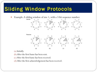
![Error detection and error correction (7) Error detection (4) CRC benefits: Detection of any single error: If G(x) contain two or more terms Detection of any double error: If G(x) dose not divide the poly. [x k +1] for all [k< frame length] Detection of any odd number error: If G(x) has the poly. [x+1] as a factor Detection of all burst errors of length<= r Standard CRC G(x)= x 32 +x 26 +x 23 +x 22 +x 16 +x 12 +x 11 +x 10 +x 8 +x 7 +x 5 +x 4 +x 2 +x 1 + 1 CRC implementation Shift register circuit](https://image.slidesharecdn.com/jaimin-chp-3-data-linklayer-2011batch-110406053224-phpapp02/85/Jaimin-chp-3-data-link-layer-2011-batch-136-320.jpg)
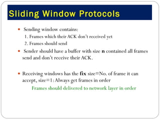
![Data Link Layer protocols (1) Definitions #define MAX PKT 1024 /* determines packet size in bytes */ typedef enum {false, true} boolean; /* boolean type */ typedef unsigned int seq_nr; /* sequence or ack numbers */ typedef struct { unsigned char data[MAX PKT]; } packet; /* packet definition */ typedef enum {data, ack, nak} frame_kind; /* frame kind definition */ typedef struct { /* frames are transported in this layer */ frame_kind kind; /* what kind of a frame is it? */ seq_nr seq; /* sequence number */ seq_nr ack; /* acknowledgement number */ packet info; /* the network layer packet */ } frame;](https://image.slidesharecdn.com/jaimin-chp-3-data-linklayer-2011batch-110406053224-phpapp02/85/Jaimin-chp-3-data-link-layer-2011-batch-160-320.jpg)

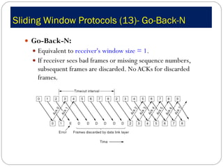
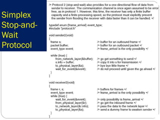
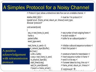
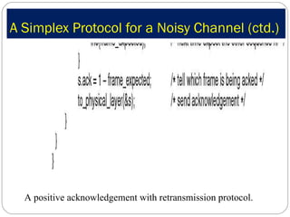
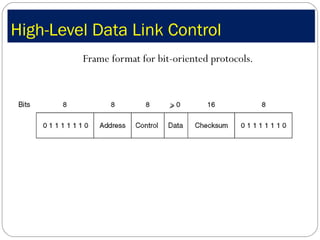
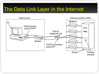
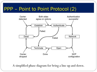

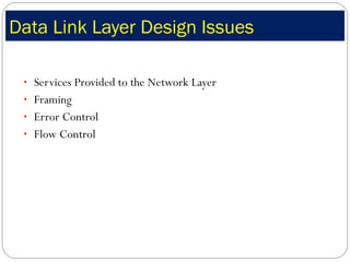
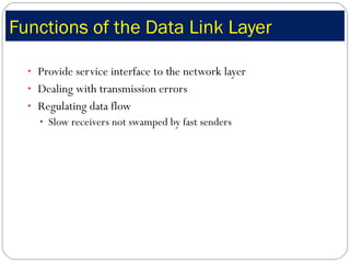
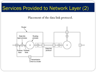
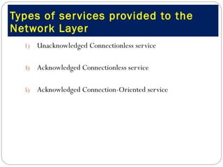
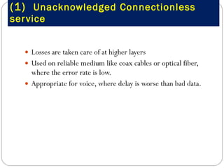
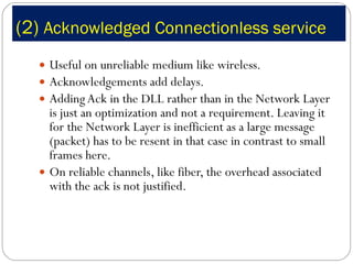
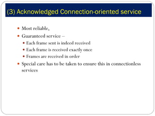
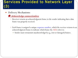
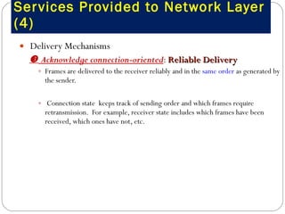
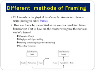
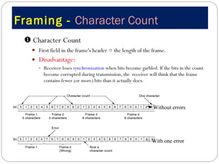
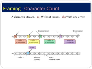
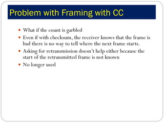
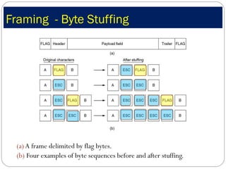
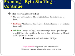
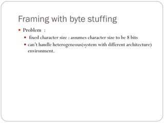
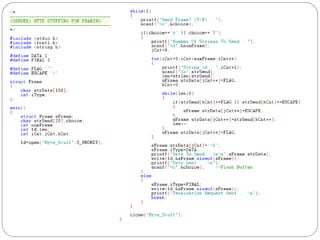
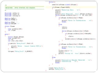
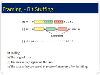
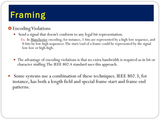
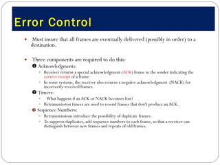
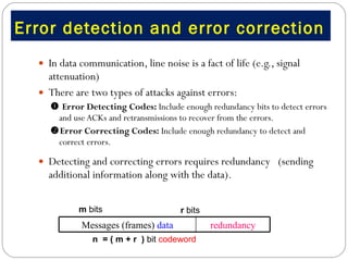
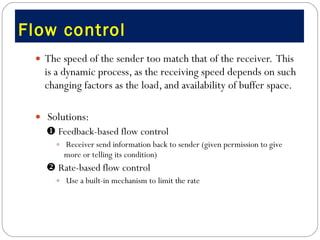
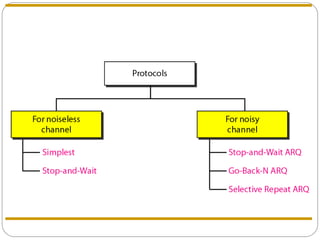
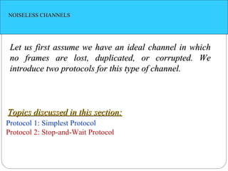
The document discusses data link layer services and functions including: 1. Providing interfaces between network layers and framing/error control/flow control. 2. Types of services include unacknowledged/acknowledged connectionless and connection-oriented. 3. Framing methods like character count, flag bytes, and encoding violations are used to delineate frames. Error control uses acknowledgments, timers, and sequence numbers.