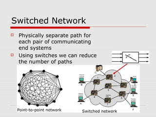
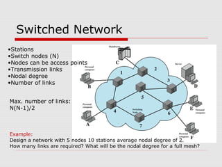
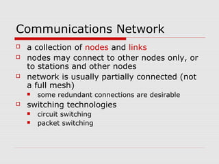
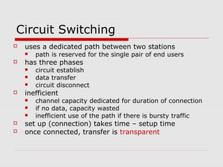
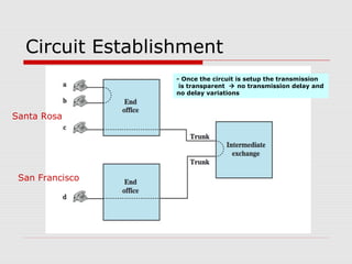
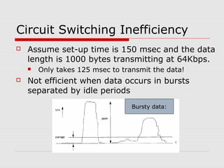
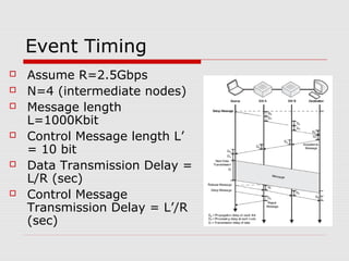
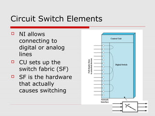
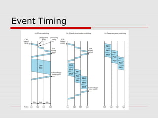
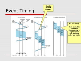
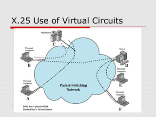
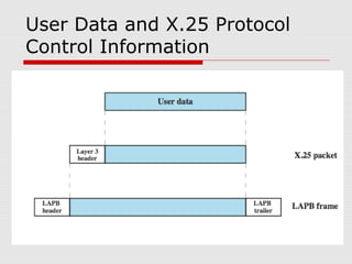
Chapter 10 
CCiirrccuuiitt SSwwiittcchhiinngg aanndd PPaacckkeett 
SSwwiittcchhiinngg
Switched Network 
 Physically separate path for 
each pair of communicating 
end systems 
 Using switches we can reduce 
the number of paths 
Point-to-point network Switched network
Switched Network 
•Stations 
•Switch nodes (N) 
•Nodes can be access points 
•Transmission links 
•Nodal degree 
•Number of links 
Max. number of links: 
N(N-1)/2 
Example: 
Design a network with 5 nodes 10 stations average nodal degree of 2. 
How many links are required? What will be the nodal degree for a full mesh?
Example 
1 
2 
5 
3 
4
Communications Network 
 a collection of nodes and links 
 nodes may connect to other nodes only, or 
to stations and other nodes 
 network is usually partially connected (not 
a full mesh) 
 some redundant connections are desirable 
 switching technologies 
 circuit switching 
 packet switching
Circuit Switching 
 uses a dedicated path between two stations 
 path is reserved for the single pair of end users 
 has three phases 
 circuit establish 
 data transfer 
 circuit disconnect 
 inefficient 
 channel capacity dedicated for duration of connection 
 if no data, capacity wasted 
 inefficient use of the path if there is bursty traffic 
 set up (connection) takes time – setup time 
 once connected, transfer is transparent
Public Circuit 
Switched Network 
Thousands of used 
May be connected 
directly to the end-office 
Dallas, TX Rohnert Park, CA 
Direct link to the 
subscriber 
caller number: 
214-403-2211 
Called user number: 
707-663-2211 
214 707 
663-xxxx 
403-xxxx 
Exchange Code 
NPA – NXX - XXXX 
Area Code 
Subscriber 
Line Number 
 North American Numbering Plan (NPAN) 
 International Direct Distance Dialing (IDDD) 
 Each country has a country code 
 To access the country code you need a notification code (0 
or 011) 
22xx
Circuit Establishment 
Santa Rosa 
San Francisco 
- Once the circuit is setup the transmission 
is transparent  no transmission delay and 
no delay variations
Circuit Switching Inefficiency 
 Assume set-up time is 150 msec and the data 
length is 1000 bytes transmitting at 64Kbps. 
 Only takes 125 msec to transmit the data! 
 Not efficient when data occurs in bursts 
separated by idle periods 
Bursty data:
Event Timing 
 Assume R=2.5Gbps 
 N=4 (intermediate nodes) 
 Message length 
L=1000Kbit 
 Control Message length L’ 
= 10 bit 
 Data Transmission Delay = 
L/R (sec) 
 Control Message 
Transmission Delay = L’/R 
(sec)
Circuit Switch Elements 
 NI allows 
connecting to 
digital or analog 
lines 
 CU sets up the 
switch fabric (SF) 
 SF is the hardware 
that actually 
causes switching
Switch Fabric using Crosspoints
Blocking or Non-blocking 
 non-blocking network 
 permits all stations to connect at once 
 used for some data connections 
 blocking network 
 may be unable to connect stations because all 
paths are in use 
 used on voice systems 
 Blocking is cheaper – hoping that not 
everyone make a call at the same time 
 Switching technologies 
 Space Division Switching 
 Time Division Switching
Space Division Switch 
 NxN crosspoints 
 For 10^6 users, a crossbar would 
require 10^12 crosspoints
Multiple Stage Space Switch 
n x k 
n x k 
n x k 
n x k 
k x n 
k x n 
k x n 
k x n 
N x N 
n n 
N x N 
n n 
N = 16 
n = 4 
k = 2 
k (N/n x N/n) 
second stages! 
16x16 Rectangular Array: 256 crosspoints 
Three Stage Switch: 96 crosspoints
Blocked Calls are possible... 
n x k 
n x k 
n x k 
n x k 
k x n 
k x n 
k x n 
k x n 
N x N 
n n 
N x N 
n n 
N = 16 
n = 4 
k = 2 
2 lines blocked. 
k (N/n x N/n) 
second stages!
3 Stage Space Division Switch 
N = 10 
n = 5 
k = 2 
3 lines 
blocked.
… also called Clos Network 
 if k = 2n-1 or greater nonblocking switch 
 If k < 2n-1, blocking can occur 
 ….. the higher k value the more crosspoints 
are required for the crossbar switch! 
 Example: suppose that 1000 users using 10 
input per input module. How many second 
stages in order to have a non-blocking 
switch?
Example - Solution 
 N=1000, n=10; 
 There are N/n = 1000/10 
= 100 switches at the 
first and third stages. 
 At the first stage, there 
are 10 x k and at the third 
stage they are k x 10 
switches. The second 
stage will have k switches 
of size 100 x 100. 
 If k = 2n-1=19, then the 
resulting switch will be 
nonblocking. 
 If k < 19, then blocking 
can occur. 
 In the case of a full 1000 x 1000 
crossbar switch, no blocking 
occurs but 1,000,000 (a million) 
crosspoints are required. 
 For n=10 and k=19, each switch 
at the first stage is a 10 x 19 
crossbar which requires 190 
crosspoints and there are 100 
such switches. 
 Same for the third stage. 
 So the first and third stages use 
2x190x100=38,000 crosspoints 
altogether. 
 The second stage consists of 
k=19 crossbars each of size 100 x 
100 because N/n=1000/10 = 
100. 
 So the second stage uses 190,000 
crosspoints. 
 Altogether, the Clos construction 
uses 228,000 crosspoints 
http://people.seas.harvard.edu/~jones/cscie129/nu_lectures/lecture11/switching/clos_network/clos_network.html
Time Division Switching 
 modern digital systems use 
intelligent control of space 
& time division elements 
 use digital time division 
techniques to set up and 
maintain virtual circuits 
 partition low speed bit 
stream into pieces that 
share higher speed stream 
 individual pieces 
manipulated by control 
logic to flow from input to 
output
http://archvlsi.ics.forth.gr/~kateveni/534/04a/s21_ts.html
Packet Switching 
 circuit switching was designed for voice 
 packet switching was designed for data 
 transmitted in small packets 
 packets contains user data and control info 
 user data may be part of a larger message 
 control info includes routing (addressing) info 
 packets are received, stored briefly 
(buffered) and past on to the next node 
 packets are queued
Packet Switching
Advantages 
 line efficiency 
 single link shared by many packets over time 
 packets queued and transmitted as fast as 
possible 
 data rate conversion 
 stations connect to local nodes at their own speed 
 nodes buffer data if required to equalize rates 
 packets accepted even when network is busy 
 priorities can be used
Data Rate Conversion 
eecs122, walrand
Switching Techniques 
 The station breaks long message into 
packets 
 Packets are sent one at a time to the 
network 
 Packets can be handled in two ways 
 datagram 
 virtual circuit
Datagram 
Diagram 
 Call setup is 
required 
 Each packet can 
pass through a 
separate path 
 Reassembly is 
required 
 Packets may 
experience jitter 
(delay variation) 
 Network can 
provide error 
control
Virtual Circuit 
Diagram 
 no call setup 
phase 
 more flexible 
 more reliable
Packet Size and 
Delay 
K Message length bit 
_ ( ) 
P Packet length bit 
_ ( ) 
R Line transmission rate bps 
_ _ ( ) 
N # switch _ nodes _ in _ the _ 
path 
D = 
K R 
N K P 
R 
= + + - 
( 1) 
( 1) 
/ 
circuit switch 
packet switch 
D K 
_ 
_ 
_ 
= + 
= 
= 
= 
= 
N 
R 
R 
D P 
message switch 
The transmission delay 
for the first packet 
N=2 
X 
a b 
Y 
Note: we are ignoring the overhead 
and setup delay and propagation delay
Example: 
 Assume the message 
is 10^6 bits long 
 Transmission rate is 
50Kbps 
 Four switches in the 
path 
 Packet size is 2000bit 
 Calculate the delay for 
packet switched 
network and circuit 
switched network 
 Neglect call setup and 
overhead 
K bit 
P bit 
R bps 
D K / 
R 
1000000 
2000 
50000 
4 
circuit _ 
switch 
= 
= 
= 
= 
= 
= = 
1000000 / 50000 20sec 
K 
D P 
N K P 
R 
= + + - = + 
PN 
( 1) (1 ) 
_ 
K 
R 
R 
= + - = 
2000(5) / 50000 (1000000 2000) / 50000 20.16sec 
N 
packet switch 
Note if P<<K then delay 
will be the same!
Circuit vs. Packet Switching 
 performance depends on various 
delays 
 propagation delay 
 transmission time 
 node delay 
 range of other characteristics, 
including: 
 transparency 
 amount of overhead
Event Timing
Event Timing 
Due to 
packet 
queue! 
No call setup 
Each packet is 
routed in 
dependently  
higher jitter 
and possibly 
delay per node
X.25 
 ITU-T standard for interface between 
host and packet switched network 
 almost universal on packet switched 
networks and packet switching in 
ISDN 
 defines three layers 
 Physical 
 Link 
 Packet
X.25 - Physical 
 interface between station node link 
 two ends are distinct 
 Data Terminal Equipment DTE (user 
equipment) 
 Data Circuit-terminating Equipment DCE 
(node) 
 physical layer specification is X.21 
 can substitute alternative such as EIA- 
232
X.25 - Link 
 Link Access Protocol Balanced (LAPB) 
 Subset of HDLC 
 see chapter 7 
 provides reliable transfer of data over 
link 
 sending as a sequence of frames
X.25 - Packet 
 provides a logical connections (virtual 
circuit) between subscribers 
 all data in this connection form a 
single stream between the end 
stations 
 established on demand 
 termed external virtual circuits
X.25 Use of Virtual Circuits
User Data and X.25 Protocol 
Control Information
Issues with X.25 
 key features include: 
 call control packets, in band signaling 
 multiplexing of virtual circuits at layer 3 
 layers 2 and 3 include flow and error 
control 
 hence have considerable overhead 
 not appropriate for modern digital 
systems with high reliability
Frame Relay 
 designed to eliminate most X.25 overhead 
 has large installed base 
 key differences: 
 call control carried in separate logical connection 
 multiplexing and switching at layer 2 
 no hop by hop error or flow control 
 hence end to end flow and error control (if used) 
are done by higher layer 
 a single user data frame is sent from source 
to destination and higher layer ACK sent 
back
Advantages and Disadvantages 
 lost link by link error and flow control 
 increased reliability means less an 
issue 
 streamlined communications process 
 lower delay 
 higher throughput 
 frame relay can be used for access 
speeds up to and over 2Mbps
Protocol Architecture
LAPF Functionality 
 LAPF (Link Access Procedure for Frame Mode 
Bearer Services) defined in Q.922 
 only core functionality used: 
 frame delimiting, alignment and transparency 
 frame mux and demux using addressing field 
 ensure frame is integral number of octets 
 ensure frame is neither too long nor short 
 detection of transmission errors 
 congestion control functions 
 form sub-layer of data link layer 
 data transfer between subscribers only
Frame Relay Data Link 
Connections 
 logical connection between 
subscribers 
 data transferred over them 
 not protected by flow or error control 
 uses separate connection for call 
control 
 overall results in significantly less 
work in network
User Data Transfer 
 only have one frame type which 
 carries user data 
 no control frames means 
 no inband signaling 
 no sequence numbers 
 flag and FCS function as in HDLC 
 address field carries DLCI 
 DLCI (Data Link Connection Identifier) 
has local significance only
Summary 
 circuit verses packet switching 
network approaches 
 X.25 
 frame relay
 http://people.seas.harvard.edu/~jones/cscie129/ Switch design 
http://www2.cs.uh.edu/~johnsson/cosc6365_08/ Circuit-Switched Coherence 
www.eecg.toronto.edu/~enright/circuit-switched- 
coherence.ppt

Chapter10 switching

  • 1.
    Chapter 10 CCiirrccuuiittSSwwiittcchhiinngg aanndd PPaacckkeett SSwwiittcchhiinngg
  • 2.
    Switched Network Physically separate path for each pair of communicating end systems  Using switches we can reduce the number of paths Point-to-point network Switched network
  • 3.
    Switched Network •Stations •Switch nodes (N) •Nodes can be access points •Transmission links •Nodal degree •Number of links Max. number of links: N(N-1)/2 Example: Design a network with 5 nodes 10 stations average nodal degree of 2. How many links are required? What will be the nodal degree for a full mesh?
  • 4.
  • 5.
    Communications Network a collection of nodes and links  nodes may connect to other nodes only, or to stations and other nodes  network is usually partially connected (not a full mesh)  some redundant connections are desirable  switching technologies  circuit switching  packet switching
  • 6.
    Circuit Switching uses a dedicated path between two stations  path is reserved for the single pair of end users  has three phases  circuit establish  data transfer  circuit disconnect  inefficient  channel capacity dedicated for duration of connection  if no data, capacity wasted  inefficient use of the path if there is bursty traffic  set up (connection) takes time – setup time  once connected, transfer is transparent
  • 7.
    Public Circuit SwitchedNetwork Thousands of used May be connected directly to the end-office Dallas, TX Rohnert Park, CA Direct link to the subscriber caller number: 214-403-2211 Called user number: 707-663-2211 214 707 663-xxxx 403-xxxx Exchange Code NPA – NXX - XXXX Area Code Subscriber Line Number  North American Numbering Plan (NPAN)  International Direct Distance Dialing (IDDD)  Each country has a country code  To access the country code you need a notification code (0 or 011) 22xx
  • 8.
    Circuit Establishment SantaRosa San Francisco - Once the circuit is setup the transmission is transparent  no transmission delay and no delay variations
  • 9.
    Circuit Switching Inefficiency  Assume set-up time is 150 msec and the data length is 1000 bytes transmitting at 64Kbps.  Only takes 125 msec to transmit the data!  Not efficient when data occurs in bursts separated by idle periods Bursty data:
  • 10.
    Event Timing Assume R=2.5Gbps  N=4 (intermediate nodes)  Message length L=1000Kbit  Control Message length L’ = 10 bit  Data Transmission Delay = L/R (sec)  Control Message Transmission Delay = L’/R (sec)
  • 11.
    Circuit Switch Elements  NI allows connecting to digital or analog lines  CU sets up the switch fabric (SF)  SF is the hardware that actually causes switching
  • 12.
  • 13.
    Blocking or Non-blocking  non-blocking network  permits all stations to connect at once  used for some data connections  blocking network  may be unable to connect stations because all paths are in use  used on voice systems  Blocking is cheaper – hoping that not everyone make a call at the same time  Switching technologies  Space Division Switching  Time Division Switching
  • 14.
    Space Division Switch  NxN crosspoints  For 10^6 users, a crossbar would require 10^12 crosspoints
  • 15.
    Multiple Stage SpaceSwitch n x k n x k n x k n x k k x n k x n k x n k x n N x N n n N x N n n N = 16 n = 4 k = 2 k (N/n x N/n) second stages! 16x16 Rectangular Array: 256 crosspoints Three Stage Switch: 96 crosspoints
  • 16.
    Blocked Calls arepossible... n x k n x k n x k n x k k x n k x n k x n k x n N x N n n N x N n n N = 16 n = 4 k = 2 2 lines blocked. k (N/n x N/n) second stages!
  • 17.
    3 Stage SpaceDivision Switch N = 10 n = 5 k = 2 3 lines blocked.
  • 18.
    … also calledClos Network  if k = 2n-1 or greater nonblocking switch  If k < 2n-1, blocking can occur  ….. the higher k value the more crosspoints are required for the crossbar switch!  Example: suppose that 1000 users using 10 input per input module. How many second stages in order to have a non-blocking switch?
  • 19.
    Example - Solution  N=1000, n=10;  There are N/n = 1000/10 = 100 switches at the first and third stages.  At the first stage, there are 10 x k and at the third stage they are k x 10 switches. The second stage will have k switches of size 100 x 100.  If k = 2n-1=19, then the resulting switch will be nonblocking.  If k < 19, then blocking can occur.  In the case of a full 1000 x 1000 crossbar switch, no blocking occurs but 1,000,000 (a million) crosspoints are required.  For n=10 and k=19, each switch at the first stage is a 10 x 19 crossbar which requires 190 crosspoints and there are 100 such switches.  Same for the third stage.  So the first and third stages use 2x190x100=38,000 crosspoints altogether.  The second stage consists of k=19 crossbars each of size 100 x 100 because N/n=1000/10 = 100.  So the second stage uses 190,000 crosspoints.  Altogether, the Clos construction uses 228,000 crosspoints http://people.seas.harvard.edu/~jones/cscie129/nu_lectures/lecture11/switching/clos_network/clos_network.html
  • 20.
    Time Division Switching  modern digital systems use intelligent control of space & time division elements  use digital time division techniques to set up and maintain virtual circuits  partition low speed bit stream into pieces that share higher speed stream  individual pieces manipulated by control logic to flow from input to output
  • 21.
  • 22.
    Packet Switching circuit switching was designed for voice  packet switching was designed for data  transmitted in small packets  packets contains user data and control info  user data may be part of a larger message  control info includes routing (addressing) info  packets are received, stored briefly (buffered) and past on to the next node  packets are queued
  • 23.
  • 24.
    Advantages  lineefficiency  single link shared by many packets over time  packets queued and transmitted as fast as possible  data rate conversion  stations connect to local nodes at their own speed  nodes buffer data if required to equalize rates  packets accepted even when network is busy  priorities can be used
  • 25.
    Data Rate Conversion eecs122, walrand
  • 26.
    Switching Techniques The station breaks long message into packets  Packets are sent one at a time to the network  Packets can be handled in two ways  datagram  virtual circuit
  • 27.
    Datagram Diagram Call setup is required  Each packet can pass through a separate path  Reassembly is required  Packets may experience jitter (delay variation)  Network can provide error control
  • 28.
    Virtual Circuit Diagram  no call setup phase  more flexible  more reliable
  • 29.
    Packet Size and Delay K Message length bit _ ( ) P Packet length bit _ ( ) R Line transmission rate bps _ _ ( ) N # switch _ nodes _ in _ the _ path D = K R N K P R = + + - ( 1) ( 1) / circuit switch packet switch D K _ _ _ = + = = = = N R R D P message switch The transmission delay for the first packet N=2 X a b Y Note: we are ignoring the overhead and setup delay and propagation delay
  • 30.
    Example:  Assumethe message is 10^6 bits long  Transmission rate is 50Kbps  Four switches in the path  Packet size is 2000bit  Calculate the delay for packet switched network and circuit switched network  Neglect call setup and overhead K bit P bit R bps D K / R 1000000 2000 50000 4 circuit _ switch = = = = = = = 1000000 / 50000 20sec K D P N K P R = + + - = + PN ( 1) (1 ) _ K R R = + - = 2000(5) / 50000 (1000000 2000) / 50000 20.16sec N packet switch Note if P<<K then delay will be the same!
  • 31.
    Circuit vs. PacketSwitching  performance depends on various delays  propagation delay  transmission time  node delay  range of other characteristics, including:  transparency  amount of overhead
  • 32.
  • 33.
    Event Timing Dueto packet queue! No call setup Each packet is routed in dependently  higher jitter and possibly delay per node
  • 34.
    X.25  ITU-Tstandard for interface between host and packet switched network  almost universal on packet switched networks and packet switching in ISDN  defines three layers  Physical  Link  Packet
  • 35.
    X.25 - Physical  interface between station node link  two ends are distinct  Data Terminal Equipment DTE (user equipment)  Data Circuit-terminating Equipment DCE (node)  physical layer specification is X.21  can substitute alternative such as EIA- 232
  • 36.
    X.25 - Link  Link Access Protocol Balanced (LAPB)  Subset of HDLC  see chapter 7  provides reliable transfer of data over link  sending as a sequence of frames
  • 37.
    X.25 - Packet  provides a logical connections (virtual circuit) between subscribers  all data in this connection form a single stream between the end stations  established on demand  termed external virtual circuits
  • 38.
    X.25 Use ofVirtual Circuits
  • 39.
    User Data andX.25 Protocol Control Information
  • 40.
    Issues with X.25  key features include:  call control packets, in band signaling  multiplexing of virtual circuits at layer 3  layers 2 and 3 include flow and error control  hence have considerable overhead  not appropriate for modern digital systems with high reliability
  • 41.
    Frame Relay designed to eliminate most X.25 overhead  has large installed base  key differences:  call control carried in separate logical connection  multiplexing and switching at layer 2  no hop by hop error or flow control  hence end to end flow and error control (if used) are done by higher layer  a single user data frame is sent from source to destination and higher layer ACK sent back
  • 42.
    Advantages and Disadvantages  lost link by link error and flow control  increased reliability means less an issue  streamlined communications process  lower delay  higher throughput  frame relay can be used for access speeds up to and over 2Mbps
  • 43.
  • 44.
    LAPF Functionality LAPF (Link Access Procedure for Frame Mode Bearer Services) defined in Q.922  only core functionality used:  frame delimiting, alignment and transparency  frame mux and demux using addressing field  ensure frame is integral number of octets  ensure frame is neither too long nor short  detection of transmission errors  congestion control functions  form sub-layer of data link layer  data transfer between subscribers only
  • 45.
    Frame Relay DataLink Connections  logical connection between subscribers  data transferred over them  not protected by flow or error control  uses separate connection for call control  overall results in significantly less work in network
  • 46.
    User Data Transfer  only have one frame type which  carries user data  no control frames means  no inband signaling  no sequence numbers  flag and FCS function as in HDLC  address field carries DLCI  DLCI (Data Link Connection Identifier) has local significance only
  • 47.
    Summary  circuitverses packet switching network approaches  X.25  frame relay
  • 48.
     http://people.seas.harvard.edu/~jones/cscie129/ Switchdesign http://www2.cs.uh.edu/~johnsson/cosc6365_08/ Circuit-Switched Coherence www.eecg.toronto.edu/~enright/circuit-switched- coherence.ppt

Editor's Notes

  • #16 &amp;lt;number&amp;gt;
  • #17 &amp;lt;number&amp;gt;
  • #48 &amp;lt;number&amp;gt;