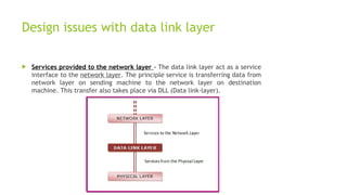
Unit-3:
Data link Layer
Outline
 Data Link layer Design Issues,
 Link layer services,
 Framing,
 Error control and Flow control,
 DLL protocols: Elementary Data Link Protocols,
 Sliding Window protocols: Protocols Verification models
Data Link layer
 Data-link layer is the second layer after the physical layer. The data link
layer is responsible for maintaining the data link between two hosts or
nodes.
 The data link layer is divided into two sub-layers :
1. Logical Link Control Sub-layer (LLC)
2. Media Access Control Sub-layer (MAC)
Data Link layer
1. Logical Link Control Sub-layer (LLC) – Provides the logic for the data link, Thus it controls
the synchronization, flow control, and error checking functions of the data link layer.
Functions are –
(i) Error Recovery.
(ii) It performs the flow control operations.
(iii) User addressing.
2. Media Access Control Sub-layer (MAC) – It is the second sub-layer of data-link layer. It
controls the flow and multiplexing for transmission medium. Transmission of data packets is
controlled by this layer. This layer is responsible for sending the data over the network
interface card. Functions are –
(i) To perform the control of access to media.
(ii) It performs the unique addressing to stations directly connected to LAN.
(iii) Detection of errors.
Design issues with data link layer
 Services provided to the network layer – The data link layer act as a service
interface to the network layer. The principle service is transferring data from
network layer on sending machine to the network layer on destination
machine. This transfer also takes place via DLL (Data link-layer).
Design issues with data link layer
 Frame synchronization – The source machine sends data in the form of
blocks called frames to the destination machine. The starting and ending of
each frame should be identified so that the frame can be recognized by the
destination machine.
Design issues with data link layer
 Flow control – Flow control is done to prevent the flow of data frame at the
receiver end. The source machine must not send data frames at a rate faster
than the capacity of destination machine to accept them.
 Error control – Error control is done to prevent duplication of frames. The
errors introduced during transmission from source to destination machines
must be detected and corrected at the destination machine.
Link layer services
 Following services are provided by the Data Link Layer:
Link layer services
 Framing & Link access: Data Link Layer protocols encapsulate each network frame
within a Link layer frame before the transmission across the link. A frame consists of
a data field in which network layer datagram is inserted and a number of data
fields. It specifies the structure of the frame as well as a channel access protocol by
which frame is to be transmitted over the link.
 Reliable delivery: Data Link Layer provides a reliable delivery service, i.e.,
transmits the network layer datagram without any error. A reliable delivery service is
accomplished with transmissions and acknowledgements. A data link layer mainly
provides the reliable delivery service over the links as they have higher error rates
and they can be corrected locally, link at which an error occurs rather than forcing
to retransmit the data.
 Flow control: A receiving node can receive the frames at a faster rate than it can
process the frame. Without flow control, the receiver's buffer can overflow, and
frames can get lost. To overcome this problem, the data link layer uses the flow
control to prevent the sending node on one side of the link from overwhelming the
receiving node on another side of the link.
Link layer services
 Error detection: Errors can be introduced by signal attenuation and noise.
Data Link Layer protocol provides a mechanism to detect one or more errors.
This is achieved by adding error detection bits in the frame and then
receiving node can perform an error check.
 Error correction: Error correction is similar to the Error detection, except
that receiving node not only detect the errors but also determine where the
errors have occurred in the frame.
 Half-Duplex & Full-Duplex: In a Full-Duplex mode, both the nodes can
transmit the data at the same time. In a Half-Duplex mode, only one node
can transmit the data at the same time.
Framing in Data Link Layer
 In the physical layer, data transmission involves synchronised transmission of
bits from the source to the destination. The data link layer packs these bits
into frames.
 Data-link layer takes the packets from the Network Layer and encapsulates
them into frames. If the frame size becomes too large, then the packet may
be divided into small sized frames. Smaller sized frames makes flow control
and error control more efficient.
 Then, it sends each frame bit-by-bit on the hardware. At receiver’s end, data
link layer picks up signals from hardware and assembles them into frames.
Parts of a Frame
 A frame has the following parts −
1. Frame Header − It contains the source and the destination addresses of the
frame.
2. Payload field − It contains the message to be delivered.
3. Trailer − It contains the error detection and error correction bits.
4. Flag − It marks the beginning and end of the frame.
Types of Framing
1. Fixed-size: The frame is of fixed size and there is no need to provide
boundaries to the frame, the length of the frame itself acts as a delimiter.
 Drawback: It suffers from internal fragmentation if the data size is less than
the frame size
 Solution: Padding
2. Variable size: In this, there is a need to define the end of the frame as well
as the beginning of the next frame to distinguish. This can be done in two
ways:
i. Length field – We can introduce a length field in the frame to indicate the
length of the frame. Used in Ethernet(802.3). The problem with this is that
sometimes the length field might get corrupted.
Types of Framing
ii. End Delimiter (ED) – We can introduce an ED(pattern) to indicate the end of
the frame. Used in Token Ring. The problem with this is that ED can occur in
the data. This can be solved by: 1. Character/Byte Stuffing: Used when
frames consist of characters. If data contains ED then, a byte is stuffed into
data to differentiate it from ED.
 Let ED = “$” –> if data contains ‘$’ anywhere, it can be escaped using ‘O’
character.
–> if data contains ‘O$’ then, use ‘OOO$'($ is escaped using O and O is
escaped using O).
Types of Framing
ii. Bit Stuffing: Let ED = 01111 and if data = 01111
–> Sender stuffs a bit to break the pattern i.e. here appends a 0 in data =
011101.
–>Receiver receives the frame.
–> If data contains 011101, receiver removes the 0 and reads the data.
FRAMING METHODS
1.Byte count
2.Flag bytes with byte stuffing
3.Flag bits with bit stuffing
4.Physical layer coding violations
16
1 FRAMING – BYTE COUNT
 Frame begins with a count of the number of bytes in it Simple, but difficult to
resynchronize after an error
17
2 FRAMING – BYTE STUFFING
•Special flag bytes delimit frames; occurrences of flags in the data must be stuffed (escaped)
•Longer, but easy to resynchronize after error
Need to escape
extra ESCAPE bytes
too!
Frame
format
Stuffin
g
example
s
18
3 FRAMING – BIT STUFFING
 Stuffing done at the bit level:
▪Frame flag has six consecutive 1s (not shown)
▪On transmit, after five 1s in the data, a 0 is added
▪On receive, a 0 after five 1s is deleted
Data
bits
Transmitted bits with
stuffing
19
Data Link Controls
 Data Link Control is the service provided by the Data Link Layer to provide
reliable data transfer over the physical medium. For example, In the half-
duplex transmission mode, one device can only transmit the data at a time. If
both the devices at the end of the links transmit the data simultaneously,
they will collide and leads to the loss of the information. The Data link layer
provides the coordination among the devices so that no collision occurs.
 The Data link layer provides three functions:
1. Line discipline
2. Flow Control
3. Error Control
Flow Control
 When a data frame (Layer-2 data) is sent from one host to another over a
single medium, it is required that the sender and receiver should work at
the same speed. That is, sender sends at a speed on which the receiver
can process and accept the data. What if the speed (hardware/software)
of the sender or receiver differs? If sender is sending too fast the receiver
may be overloaded, (swamped) and data may be lost.
 Two types of mechanisms can be deployed to control the flow:
1. Stop and Wait
 This flow control mechanism forces the sender after transmitting a data
frame to stop and wait until the acknowledgement of the data-frame sent
is received.
Flow Control
2. Sliding Window
 The Sliding Window is a method of flow control in which a sender can transmit the several frames
before getting an acknowledgement.
 In Sliding Window Control, multiple frames can be sent one after the another due to which capacity
of the communication channel can be utilized efficiently.
 A single ACK acknowledge multiple frames.
 Sliding Window refers to imaginary boxes at both the sender and receiver end.
 The window can hold the frames at either end, and it provides the upper limit on the number of
frames that can be transmitted before the acknowledgement.
 Frames can be acknowledged even when the window is not completely filled.
 The window has a specific size in which they are numbered as modulo-n means that they are
numbered from 0 to n-1. For example, if n = 8, the frames are numbered from
0,1,2,3,4,5,6,7,0,1,2,3,4,5,6,7,0,1........
 The size of the window is represented as n-1. Therefore, maximum n-1 frames can be sent before
acknowledgement.
 When the receiver sends the ACK, it includes the number of the next frame that it wants to receive.
For example, to acknowledge the string of frames ending with frame number 4, the receiver will
send the ACK containing the number 5. When the sender sees the ACK with the number 5, it got to
know that the frames from 0 through 4 have been received.
Sender Window Receiver Window
ERROR CONTROL
 The data link layer ensures error free link for data transmission. The issues it caters to with
respect to error control are −
•Dealing with transmission errors
•Sending acknowledgement frames in reliable connections
•Retransmitting lost frames
•Identifying duplicate frames and deleting them
•Controlling access to shared channels in case of broadcasting
24
ERROR CONTROL
•Data can be corrupted during transmission. For reliable communication, errors must be
detected and corrected. Signals flows from one point to another.
•This is subjected to unpredictable interferences from heat, magnetism and other forms of
electricity.
• Any reliable system must have a mechanism for detecting and correcting such errors. Error
detection and correction occur at both the transport layer and the data link layer.
•Here we will talk about the data link layer and check bit by bit that if there is any error or
not.
25
ERROR CONTROL
 TYPES OF ERRORS:
1.Single bit Error:
 The term single bit error means that only one bit of a given data unit is changed
 from 1 to 0 or 0 to 1. 010101 is changed to 110101 here only one bit is changed
 by single bit error.
 Example: If the sender sends 101(5) to the receiver but the receiver receives 100(4) then it is a single bit
error.
 101(sent bits) 100(received bits)
→
2. Burst Error:
 When there is a change in two or more bits of the sender’s data then it is called a burst error.
 Example: If the sender sends 1011(11) to the sender but the receiver receives 1000(8) then it is a burst error.
 1011(sent bits) 1000(received bits)
→
26
PHASES IN ERROR CONTROL
The error control mechanism in data link layer involves the following phases −
1. Detection of Error − Transmission error, if any, is detected by either the sender or the
receiver.
2. Acknowledgment − acknowledgment may be positive or negative.
1. Positive ACK − On receiving a correct frame, the receiver sends a positive acknowledge.
2. Negative ACK − On receiving a damaged frame or a duplicate frame, the receiver sends a negative
acknowledgment back to the sender.
3. Retransmission − The sender maintains a clock and sets a timeout period. If an
acknowledgment of a data-frame previously transmitted does not arrive before the
timeout, or a negative acknowledgment is received, the sender retransmits the frame.
27
ERROR CONTROL
28
ERROR CORRECTION :
 Error correction, as name suggests, simply means correction or solving or fixing of errors.
 It simply means reconstruction and rehabilitation of original data that is error-free. But
error correction method is very costly and is very hard.
29
ERROR CORRECTION :HAMMING
 Hamming distance is the number of bit positions by which two codewords differ.
 If codewords are a Hamming distance of d apart, it will require d single-bit errors to
convert one to the other
 Example of a universe comprising 4 valid codewords of 10 bits (m=2, r=8):
 0000000000, 0000011111, 1111100000, and 1111111111
 Hamming distance of this example is 5
 Error-detecting and error-correcting properties of a block code depend upon its Hamming
Distance (d = bit error difference between two codes)
30
ERROR CORRECTION :HAMMING
It is a single bit error correction method using redundant bits.
In this method redundant bits are included with the original data. Now, the bits are arranged such that different
incorrect bits produce different error results and the corrupt bit can be identified. Once the bit is identified,
the receiver can reverse its value and correct the error. Hamming code can be applied to any length of data unit
and uses the relationships between the data and the redundancy bits.
• Algorithm:
• Parity bits are positions at the power of two (2 r).
• Rest of the positions is filled by original data.
• Each parity bit will take care of its bits in the code.
• Final code will sends to the receiver.
In the above example we calculates the even parities for the various bit combinations. the value for the each
combination is the value for the corresponding r(redundancy)bit. r1 will take care of bit 1,3,5,7,9,11. and it is
set based on the sum of even parity bit. the same method for rest of the parity bits.
If the error occurred at bit 7 which is changed from 1 to 0, then receiver recalculates the same sets of bits used
by the sender. By this we can identify the perfect location of error occurrence. once the bit is identified the
receiver can reverse its value and correct the error.
31
ERROR DETECTION
 Error detection is the process of detecting the error during the transmission between the
sender and the receiver.
 Types of error detection-
1. Parity checking
2. Cyclic Redundancy Check (CRC)
3. Checksum
32
ERROR DETECTING TECHNIQUES:
1. The most popular Error Detecting Techniques are:
2. Single parity check
3. Two-dimensional parity check
4. Checksum
5. Cyclic redundancy check
33
ERROR DETECTION-SINGLE PARITY CHECK
1. Simple Parity check
Blocks of data from the source are subjected to a check bit or parity bit generator form,
where a parity of :
 1 is added to the block if it contains odd number of 1’s, and
 0 is added if it contains even number of 1’s
 This scheme makes the total number of 1’s even, that is why it is called even parity
checking.
34
ERROR DETECTION-SINGLE PARITY CHECK
 Single Parity checking is the simple mechanism and inexpensive to detect the errors.
 In this technique, a redundant bit is also known as a parity bit which is appended at the
end of the data unit so that the number of 1s becomes even. Therefore, the total number
of transmitted bits would be 9 bits.
 If the number of 1s bits is odd, then parity bit 1 is appended and if the number of 1s bits is
even, then parity bit 0 is appended at the end of the data unit.
 At the receiving end, the parity bit is calculated from the received data bits and compared
with the received parity bit.
 This technique generates the total number of 1s even, so it is known as even-parity
checking.
35
ERROR DETECTION-SINGLE PARITY CHECK
36
2. TWO-DIMENSIONAL PARITY CHECK:
For each row, parity check bits are calculated, which is identical to a basic parity check bit.
For each column, parity check bits are computed and transmitted together with the
data.These are compared with the parity bits calculated on the received data at the
receiving end.
37
3. CHECKSUM:
 The data is split into k segments of m bits each in the checksum error detection
technique.
 To get the total, the segments are summed at the sender’s end using 1’s complement
arithmetic. To obtain the checksum, a complement of the sum is taken.
 The checksum segment is sent with the data segments.
 To obtain the total, all received segments are summed using 1’s complement arithmetic at
the receiver’s end. The sum is then calculated.
 If the result is 0, the data is accepted; otherwise, it is rejected.
38
3. CHECKSUM:
In checksum error detection scheme, the data is divided into k segments each of m bits.
In the sender’s end the segments are added using 1’s complement arithmetic to get the
sum. The sum is complemented to get the checksum.
The checksum segment is sent along with the data segments.
At the receiver’s end, all received segments are added using 1’s complement arithmetic to
get the sum. The sum is complemented.
If the result is zero, the received data is accepted; otherwise discarded.
39
3. CHECKSUM:
40
4. CYCLIC REDUNDANCY CHECK:
The Cyclic Redundancy Checks (CRC) is the most powerful method for Error-Detection and
Correction.
It is given as a kbit message and the transmitter creates an (n – k) bit sequence called
frame check sequence.
The out coming frame, including n bits, is precisely divisible by some fixed number. Modulo
2 Arithmetic is used in this binary addition with no carries, just like the XOR operation.
Redundancy means duplicity. The redundancy bits used by CRC are changed by splitting the
data unit by a fixed divisor. The remainder is CRC.
41
4. CYCLIC REDUNDANCY CHECK:
 Qualities of CRC
It should have accurately one less bit than the divisor.
Joining it to the end of the data unit should create the resulting bit sequence precisely
divisible by the divisor.
42
4. CYCLIC REDUNDANCY CHECK:
CRC generator and checker
43
4. CYCLIC REDUNDANCY CHECK:EXAMPLE
44
4. CYCLIC REDUNDANCY CHECK:
 CRC is an alternative method for determining whether or not a received frame includes valid
data. The binary division of the data bits being delivered is used in this approach.
Polynomials are used to generate the divisor.
 The sender divides the bits that are being transferred and calculates the remainder.
 The sender inserts the remainder at the end of the original bits before sending the actual
bits. A codeword is made up of the actual data bits plus the remainder.
 The transmitter sends data bits in the form of codewords.
 The receiver, on the other hand, divides the codewords using the same CRC divisor.
 If the remainder consists entirely of zeros, the data bits are validated; otherwise, it is
assumed that some data corruption happened during transmission.
45
DLL protocols: Elementary Data Link
Protocols
 Elementary Data Link protocols are classified into three categories, as given
below −
1. Protocol 1 − Unrestricted simplex protocol
2. Protocol 2 − Simplex stop and wait protocol
3. Protocol 3 − Simplex protocol for noisy channels.
Unrestricted Simplex Protocol
 Data transmitting is carried out in one direction
only. The transmission (Tx) and receiving (Rx) are
always ready and the processing time can be
ignored. In this protocol, infinite buffer space is
available, and no errors are occurring that is no
damage frames and no lost frames.
Simplex Stop and Wait protocol
 In this protocol we assume that data is transmitted in one direction
only. No error occurs; the receiver can only process the received
information at finite rate. These assumptions imply that the
transmitter cannot send frames at rate faster than the receiver can
process them.
 The main problem here is how to prevent the sender from flooding the
receiver. The general solution for this problem is to have the receiver
send some sort of feedback to sender, the process is as follows −
 Step1 − The receiver send the acknowledgement frame back to the
sender telling the sender that the last received frame has been
processed and passed to the host.
 Step 2 − Permission to send the next frame is granted.
 Step 3 − The sender after sending the sent frame has to wait for an
acknowledge frame from the receiver before sending another frame.
 This protocol is called Simplex Stop and wait protocol, the sender
sends one frame and waits for feedback from the receiver. When the
ACK arrives, the sender sends the next frame.
Simplex Protocol for Noisy Channel
 Data transfer is only in one direction, consider
separate sender and receiver, finite processing
capacity and speed at the receiver, since it is a
noisy channel, errors in data frames or
acknowledgement frames are expected. Every
frame has a unique sequence number.
 After a frame has been transmitted, the timer is
started for a finite time. Before the timer
expires, if the acknowledgement is not received ,
the frame gets retransmitted, when the
acknowledgement gets corrupted or sent data
frames gets damaged, how long the sender should
wait to transmit the next frame is infinite.
Sliding Window protocols: Protocols
Verification models
 The sliding window is a technique for sending multiple frames at a time. It
controls the data packets between the two devices where reliable and
gradual delivery of data frames is needed. It is also used in TCP (Transmission
Control Protocol).
 In this technique, each frame has sent from the sequence number. The
sequence numbers are used to find the missing data in the receiver end. The
purpose of the sliding window technique is to avoid duplicate data, so it uses
the sequence number.
 Sliding window protocol has two types:
1. Go-Back-N ARQ
2. Selective Repeat ARQ
Go-Back-N ARQ
 Go-Back-N ARQ protocol is also known as Go-Back-N Automatic Repeat
Request. It is a data link layer protocol that uses a sliding window method. In
this, if any frame is corrupted or lost, all subsequent frames have to be sent
again.
 The size of the sender window is N in this protocol. For example, Go-Back-8,
the size of the sender window, will be 8. The receiver window size is always
1.
 If the receiver receives a corrupted frame, it cancels it. The receiver does not
accept a corrupted frame. When the timer expires, the sender sends the
correct frame again. The design of the Go-Back-N ARQ protocol is shown
below.
The example of Go-Back-N ARQ is shown
below in the figure.
Selective Repeat ARQ
 Selective Repeat ARQ is also known as the Selective Repeat Automatic Repeat
Request. It is a data link layer protocol that uses a sliding window method.
The Go-back-N ARQ protocol works well if it has fewer errors. But if there is a
lot of error in the frame, lots of bandwidth loss in sending the frames again.
So, we use the Selective Repeat ARQ protocol. In this protocol, the size of the
sender window is always equal to the size of the receiver window. The size of
the sliding window is always greater than 1.
 If the receiver receives a corrupt frame, it does not directly discard it. It
sends a negative acknowledgment to the sender. The sender sends that frame
again as soon as on the receiving negative acknowledgment. There is no
waiting for any time-out to send that frame. The design of the Selective
Repeat ARQ protocol is shown below.
The example of the Selective Repeat ARQ
protocol is shown below in the figure.
Difference between the Go-Back-N ARQ and Selective
Repeat ARQ
Go-Back-N ARQ Selective Repeat ARQ
If a frame is corrupted or lost in it,all subsequent
frames have to be sent again.
In this, only the frame is sent again, which is
corrupted or lost.
If it has a high error rate,it wastes a lot of bandwidth. There is a loss of low bandwidth.
It is less complex. It is more complex because it has to do sorting and
searching as well. And it also requires more storage.
It does not require sorting. In this, sorting is done to get the frames in the
correct order.
It does not require searching. The search operation is performed in it.
It is used more. It is used less because it is more complex.
THANK YOU….

Computer Networks (Computer Engineering) Unit-3 Data Link Layer & its Protocols..pptx

  • 1.
  • 2.
    Outline  Data Linklayer Design Issues,  Link layer services,  Framing,  Error control and Flow control,  DLL protocols: Elementary Data Link Protocols,  Sliding Window protocols: Protocols Verification models
  • 3.
    Data Link layer Data-link layer is the second layer after the physical layer. The data link layer is responsible for maintaining the data link between two hosts or nodes.  The data link layer is divided into two sub-layers : 1. Logical Link Control Sub-layer (LLC) 2. Media Access Control Sub-layer (MAC)
  • 4.
    Data Link layer 1.Logical Link Control Sub-layer (LLC) – Provides the logic for the data link, Thus it controls the synchronization, flow control, and error checking functions of the data link layer. Functions are – (i) Error Recovery. (ii) It performs the flow control operations. (iii) User addressing. 2. Media Access Control Sub-layer (MAC) – It is the second sub-layer of data-link layer. It controls the flow and multiplexing for transmission medium. Transmission of data packets is controlled by this layer. This layer is responsible for sending the data over the network interface card. Functions are – (i) To perform the control of access to media. (ii) It performs the unique addressing to stations directly connected to LAN. (iii) Detection of errors.
  • 5.
    Design issues withdata link layer  Services provided to the network layer – The data link layer act as a service interface to the network layer. The principle service is transferring data from network layer on sending machine to the network layer on destination machine. This transfer also takes place via DLL (Data link-layer).
  • 6.
    Design issues withdata link layer  Frame synchronization – The source machine sends data in the form of blocks called frames to the destination machine. The starting and ending of each frame should be identified so that the frame can be recognized by the destination machine.
  • 7.
    Design issues withdata link layer  Flow control – Flow control is done to prevent the flow of data frame at the receiver end. The source machine must not send data frames at a rate faster than the capacity of destination machine to accept them.  Error control – Error control is done to prevent duplication of frames. The errors introduced during transmission from source to destination machines must be detected and corrected at the destination machine.
  • 8.
    Link layer services Following services are provided by the Data Link Layer:
  • 9.
    Link layer services Framing & Link access: Data Link Layer protocols encapsulate each network frame within a Link layer frame before the transmission across the link. A frame consists of a data field in which network layer datagram is inserted and a number of data fields. It specifies the structure of the frame as well as a channel access protocol by which frame is to be transmitted over the link.  Reliable delivery: Data Link Layer provides a reliable delivery service, i.e., transmits the network layer datagram without any error. A reliable delivery service is accomplished with transmissions and acknowledgements. A data link layer mainly provides the reliable delivery service over the links as they have higher error rates and they can be corrected locally, link at which an error occurs rather than forcing to retransmit the data.  Flow control: A receiving node can receive the frames at a faster rate than it can process the frame. Without flow control, the receiver's buffer can overflow, and frames can get lost. To overcome this problem, the data link layer uses the flow control to prevent the sending node on one side of the link from overwhelming the receiving node on another side of the link.
  • 10.
    Link layer services Error detection: Errors can be introduced by signal attenuation and noise. Data Link Layer protocol provides a mechanism to detect one or more errors. This is achieved by adding error detection bits in the frame and then receiving node can perform an error check.  Error correction: Error correction is similar to the Error detection, except that receiving node not only detect the errors but also determine where the errors have occurred in the frame.  Half-Duplex & Full-Duplex: In a Full-Duplex mode, both the nodes can transmit the data at the same time. In a Half-Duplex mode, only one node can transmit the data at the same time.
  • 11.
    Framing in DataLink Layer  In the physical layer, data transmission involves synchronised transmission of bits from the source to the destination. The data link layer packs these bits into frames.  Data-link layer takes the packets from the Network Layer and encapsulates them into frames. If the frame size becomes too large, then the packet may be divided into small sized frames. Smaller sized frames makes flow control and error control more efficient.  Then, it sends each frame bit-by-bit on the hardware. At receiver’s end, data link layer picks up signals from hardware and assembles them into frames.
  • 12.
    Parts of aFrame  A frame has the following parts − 1. Frame Header − It contains the source and the destination addresses of the frame. 2. Payload field − It contains the message to be delivered. 3. Trailer − It contains the error detection and error correction bits. 4. Flag − It marks the beginning and end of the frame.
  • 13.
    Types of Framing 1.Fixed-size: The frame is of fixed size and there is no need to provide boundaries to the frame, the length of the frame itself acts as a delimiter.  Drawback: It suffers from internal fragmentation if the data size is less than the frame size  Solution: Padding 2. Variable size: In this, there is a need to define the end of the frame as well as the beginning of the next frame to distinguish. This can be done in two ways: i. Length field – We can introduce a length field in the frame to indicate the length of the frame. Used in Ethernet(802.3). The problem with this is that sometimes the length field might get corrupted.
  • 14.
    Types of Framing ii.End Delimiter (ED) – We can introduce an ED(pattern) to indicate the end of the frame. Used in Token Ring. The problem with this is that ED can occur in the data. This can be solved by: 1. Character/Byte Stuffing: Used when frames consist of characters. If data contains ED then, a byte is stuffed into data to differentiate it from ED.  Let ED = “$” –> if data contains ‘$’ anywhere, it can be escaped using ‘O’ character. –> if data contains ‘O$’ then, use ‘OOO$'($ is escaped using O and O is escaped using O).
  • 15.
    Types of Framing ii.Bit Stuffing: Let ED = 01111 and if data = 01111 –> Sender stuffs a bit to break the pattern i.e. here appends a 0 in data = 011101. –>Receiver receives the frame. –> If data contains 011101, receiver removes the 0 and reads the data.
  • 16.
    FRAMING METHODS 1.Byte count 2.Flagbytes with byte stuffing 3.Flag bits with bit stuffing 4.Physical layer coding violations 16
  • 17.
    1 FRAMING –BYTE COUNT  Frame begins with a count of the number of bytes in it Simple, but difficult to resynchronize after an error 17
  • 18.
    2 FRAMING –BYTE STUFFING •Special flag bytes delimit frames; occurrences of flags in the data must be stuffed (escaped) •Longer, but easy to resynchronize after error Need to escape extra ESCAPE bytes too! Frame format Stuffin g example s 18
  • 19.
    3 FRAMING –BIT STUFFING  Stuffing done at the bit level: ▪Frame flag has six consecutive 1s (not shown) ▪On transmit, after five 1s in the data, a 0 is added ▪On receive, a 0 after five 1s is deleted Data bits Transmitted bits with stuffing 19
  • 20.
    Data Link Controls Data Link Control is the service provided by the Data Link Layer to provide reliable data transfer over the physical medium. For example, In the half- duplex transmission mode, one device can only transmit the data at a time. If both the devices at the end of the links transmit the data simultaneously, they will collide and leads to the loss of the information. The Data link layer provides the coordination among the devices so that no collision occurs.  The Data link layer provides three functions: 1. Line discipline 2. Flow Control 3. Error Control
  • 21.
    Flow Control  Whena data frame (Layer-2 data) is sent from one host to another over a single medium, it is required that the sender and receiver should work at the same speed. That is, sender sends at a speed on which the receiver can process and accept the data. What if the speed (hardware/software) of the sender or receiver differs? If sender is sending too fast the receiver may be overloaded, (swamped) and data may be lost.  Two types of mechanisms can be deployed to control the flow: 1. Stop and Wait  This flow control mechanism forces the sender after transmitting a data frame to stop and wait until the acknowledgement of the data-frame sent is received.
  • 22.
    Flow Control 2. SlidingWindow  The Sliding Window is a method of flow control in which a sender can transmit the several frames before getting an acknowledgement.  In Sliding Window Control, multiple frames can be sent one after the another due to which capacity of the communication channel can be utilized efficiently.  A single ACK acknowledge multiple frames.  Sliding Window refers to imaginary boxes at both the sender and receiver end.  The window can hold the frames at either end, and it provides the upper limit on the number of frames that can be transmitted before the acknowledgement.  Frames can be acknowledged even when the window is not completely filled.  The window has a specific size in which they are numbered as modulo-n means that they are numbered from 0 to n-1. For example, if n = 8, the frames are numbered from 0,1,2,3,4,5,6,7,0,1,2,3,4,5,6,7,0,1........  The size of the window is represented as n-1. Therefore, maximum n-1 frames can be sent before acknowledgement.  When the receiver sends the ACK, it includes the number of the next frame that it wants to receive. For example, to acknowledge the string of frames ending with frame number 4, the receiver will send the ACK containing the number 5. When the sender sees the ACK with the number 5, it got to know that the frames from 0 through 4 have been received.
  • 23.
  • 24.
    ERROR CONTROL  Thedata link layer ensures error free link for data transmission. The issues it caters to with respect to error control are − •Dealing with transmission errors •Sending acknowledgement frames in reliable connections •Retransmitting lost frames •Identifying duplicate frames and deleting them •Controlling access to shared channels in case of broadcasting 24
  • 25.
    ERROR CONTROL •Data canbe corrupted during transmission. For reliable communication, errors must be detected and corrected. Signals flows from one point to another. •This is subjected to unpredictable interferences from heat, magnetism and other forms of electricity. • Any reliable system must have a mechanism for detecting and correcting such errors. Error detection and correction occur at both the transport layer and the data link layer. •Here we will talk about the data link layer and check bit by bit that if there is any error or not. 25
  • 26.
    ERROR CONTROL  TYPESOF ERRORS: 1.Single bit Error:  The term single bit error means that only one bit of a given data unit is changed  from 1 to 0 or 0 to 1. 010101 is changed to 110101 here only one bit is changed  by single bit error.  Example: If the sender sends 101(5) to the receiver but the receiver receives 100(4) then it is a single bit error.  101(sent bits) 100(received bits) → 2. Burst Error:  When there is a change in two or more bits of the sender’s data then it is called a burst error.  Example: If the sender sends 1011(11) to the sender but the receiver receives 1000(8) then it is a burst error.  1011(sent bits) 1000(received bits) → 26
  • 27.
    PHASES IN ERRORCONTROL The error control mechanism in data link layer involves the following phases − 1. Detection of Error − Transmission error, if any, is detected by either the sender or the receiver. 2. Acknowledgment − acknowledgment may be positive or negative. 1. Positive ACK − On receiving a correct frame, the receiver sends a positive acknowledge. 2. Negative ACK − On receiving a damaged frame or a duplicate frame, the receiver sends a negative acknowledgment back to the sender. 3. Retransmission − The sender maintains a clock and sets a timeout period. If an acknowledgment of a data-frame previously transmitted does not arrive before the timeout, or a negative acknowledgment is received, the sender retransmits the frame. 27
  • 28.
  • 29.
    ERROR CORRECTION : Error correction, as name suggests, simply means correction or solving or fixing of errors.  It simply means reconstruction and rehabilitation of original data that is error-free. But error correction method is very costly and is very hard. 29
  • 30.
    ERROR CORRECTION :HAMMING Hamming distance is the number of bit positions by which two codewords differ.  If codewords are a Hamming distance of d apart, it will require d single-bit errors to convert one to the other  Example of a universe comprising 4 valid codewords of 10 bits (m=2, r=8):  0000000000, 0000011111, 1111100000, and 1111111111  Hamming distance of this example is 5  Error-detecting and error-correcting properties of a block code depend upon its Hamming Distance (d = bit error difference between two codes) 30
  • 31.
    ERROR CORRECTION :HAMMING Itis a single bit error correction method using redundant bits. In this method redundant bits are included with the original data. Now, the bits are arranged such that different incorrect bits produce different error results and the corrupt bit can be identified. Once the bit is identified, the receiver can reverse its value and correct the error. Hamming code can be applied to any length of data unit and uses the relationships between the data and the redundancy bits. • Algorithm: • Parity bits are positions at the power of two (2 r). • Rest of the positions is filled by original data. • Each parity bit will take care of its bits in the code. • Final code will sends to the receiver. In the above example we calculates the even parities for the various bit combinations. the value for the each combination is the value for the corresponding r(redundancy)bit. r1 will take care of bit 1,3,5,7,9,11. and it is set based on the sum of even parity bit. the same method for rest of the parity bits. If the error occurred at bit 7 which is changed from 1 to 0, then receiver recalculates the same sets of bits used by the sender. By this we can identify the perfect location of error occurrence. once the bit is identified the receiver can reverse its value and correct the error. 31
  • 32.
    ERROR DETECTION  Errordetection is the process of detecting the error during the transmission between the sender and the receiver.  Types of error detection- 1. Parity checking 2. Cyclic Redundancy Check (CRC) 3. Checksum 32
  • 33.
    ERROR DETECTING TECHNIQUES: 1.The most popular Error Detecting Techniques are: 2. Single parity check 3. Two-dimensional parity check 4. Checksum 5. Cyclic redundancy check 33
  • 34.
    ERROR DETECTION-SINGLE PARITYCHECK 1. Simple Parity check Blocks of data from the source are subjected to a check bit or parity bit generator form, where a parity of :  1 is added to the block if it contains odd number of 1’s, and  0 is added if it contains even number of 1’s  This scheme makes the total number of 1’s even, that is why it is called even parity checking. 34
  • 35.
    ERROR DETECTION-SINGLE PARITYCHECK  Single Parity checking is the simple mechanism and inexpensive to detect the errors.  In this technique, a redundant bit is also known as a parity bit which is appended at the end of the data unit so that the number of 1s becomes even. Therefore, the total number of transmitted bits would be 9 bits.  If the number of 1s bits is odd, then parity bit 1 is appended and if the number of 1s bits is even, then parity bit 0 is appended at the end of the data unit.  At the receiving end, the parity bit is calculated from the received data bits and compared with the received parity bit.  This technique generates the total number of 1s even, so it is known as even-parity checking. 35
  • 36.
  • 37.
    2. TWO-DIMENSIONAL PARITYCHECK: For each row, parity check bits are calculated, which is identical to a basic parity check bit. For each column, parity check bits are computed and transmitted together with the data.These are compared with the parity bits calculated on the received data at the receiving end. 37
  • 38.
    3. CHECKSUM:  Thedata is split into k segments of m bits each in the checksum error detection technique.  To get the total, the segments are summed at the sender’s end using 1’s complement arithmetic. To obtain the checksum, a complement of the sum is taken.  The checksum segment is sent with the data segments.  To obtain the total, all received segments are summed using 1’s complement arithmetic at the receiver’s end. The sum is then calculated.  If the result is 0, the data is accepted; otherwise, it is rejected. 38
  • 39.
    3. CHECKSUM: In checksumerror detection scheme, the data is divided into k segments each of m bits. In the sender’s end the segments are added using 1’s complement arithmetic to get the sum. The sum is complemented to get the checksum. The checksum segment is sent along with the data segments. At the receiver’s end, all received segments are added using 1’s complement arithmetic to get the sum. The sum is complemented. If the result is zero, the received data is accepted; otherwise discarded. 39
  • 40.
  • 41.
    4. CYCLIC REDUNDANCYCHECK: The Cyclic Redundancy Checks (CRC) is the most powerful method for Error-Detection and Correction. It is given as a kbit message and the transmitter creates an (n – k) bit sequence called frame check sequence. The out coming frame, including n bits, is precisely divisible by some fixed number. Modulo 2 Arithmetic is used in this binary addition with no carries, just like the XOR operation. Redundancy means duplicity. The redundancy bits used by CRC are changed by splitting the data unit by a fixed divisor. The remainder is CRC. 41
  • 42.
    4. CYCLIC REDUNDANCYCHECK:  Qualities of CRC It should have accurately one less bit than the divisor. Joining it to the end of the data unit should create the resulting bit sequence precisely divisible by the divisor. 42
  • 43.
    4. CYCLIC REDUNDANCYCHECK: CRC generator and checker 43
  • 44.
    4. CYCLIC REDUNDANCYCHECK:EXAMPLE 44
  • 45.
    4. CYCLIC REDUNDANCYCHECK:  CRC is an alternative method for determining whether or not a received frame includes valid data. The binary division of the data bits being delivered is used in this approach. Polynomials are used to generate the divisor.  The sender divides the bits that are being transferred and calculates the remainder.  The sender inserts the remainder at the end of the original bits before sending the actual bits. A codeword is made up of the actual data bits plus the remainder.  The transmitter sends data bits in the form of codewords.  The receiver, on the other hand, divides the codewords using the same CRC divisor.  If the remainder consists entirely of zeros, the data bits are validated; otherwise, it is assumed that some data corruption happened during transmission. 45
  • 46.
    DLL protocols: ElementaryData Link Protocols  Elementary Data Link protocols are classified into three categories, as given below − 1. Protocol 1 − Unrestricted simplex protocol 2. Protocol 2 − Simplex stop and wait protocol 3. Protocol 3 − Simplex protocol for noisy channels.
  • 47.
    Unrestricted Simplex Protocol Data transmitting is carried out in one direction only. The transmission (Tx) and receiving (Rx) are always ready and the processing time can be ignored. In this protocol, infinite buffer space is available, and no errors are occurring that is no damage frames and no lost frames.
  • 48.
    Simplex Stop andWait protocol  In this protocol we assume that data is transmitted in one direction only. No error occurs; the receiver can only process the received information at finite rate. These assumptions imply that the transmitter cannot send frames at rate faster than the receiver can process them.  The main problem here is how to prevent the sender from flooding the receiver. The general solution for this problem is to have the receiver send some sort of feedback to sender, the process is as follows −  Step1 − The receiver send the acknowledgement frame back to the sender telling the sender that the last received frame has been processed and passed to the host.  Step 2 − Permission to send the next frame is granted.  Step 3 − The sender after sending the sent frame has to wait for an acknowledge frame from the receiver before sending another frame.  This protocol is called Simplex Stop and wait protocol, the sender sends one frame and waits for feedback from the receiver. When the ACK arrives, the sender sends the next frame.
  • 49.
    Simplex Protocol forNoisy Channel  Data transfer is only in one direction, consider separate sender and receiver, finite processing capacity and speed at the receiver, since it is a noisy channel, errors in data frames or acknowledgement frames are expected. Every frame has a unique sequence number.  After a frame has been transmitted, the timer is started for a finite time. Before the timer expires, if the acknowledgement is not received , the frame gets retransmitted, when the acknowledgement gets corrupted or sent data frames gets damaged, how long the sender should wait to transmit the next frame is infinite.
  • 50.
    Sliding Window protocols:Protocols Verification models  The sliding window is a technique for sending multiple frames at a time. It controls the data packets between the two devices where reliable and gradual delivery of data frames is needed. It is also used in TCP (Transmission Control Protocol).  In this technique, each frame has sent from the sequence number. The sequence numbers are used to find the missing data in the receiver end. The purpose of the sliding window technique is to avoid duplicate data, so it uses the sequence number.  Sliding window protocol has two types: 1. Go-Back-N ARQ 2. Selective Repeat ARQ
  • 51.
    Go-Back-N ARQ  Go-Back-NARQ protocol is also known as Go-Back-N Automatic Repeat Request. It is a data link layer protocol that uses a sliding window method. In this, if any frame is corrupted or lost, all subsequent frames have to be sent again.  The size of the sender window is N in this protocol. For example, Go-Back-8, the size of the sender window, will be 8. The receiver window size is always 1.  If the receiver receives a corrupted frame, it cancels it. The receiver does not accept a corrupted frame. When the timer expires, the sender sends the correct frame again. The design of the Go-Back-N ARQ protocol is shown below.
  • 53.
    The example ofGo-Back-N ARQ is shown below in the figure.
  • 54.
    Selective Repeat ARQ Selective Repeat ARQ is also known as the Selective Repeat Automatic Repeat Request. It is a data link layer protocol that uses a sliding window method. The Go-back-N ARQ protocol works well if it has fewer errors. But if there is a lot of error in the frame, lots of bandwidth loss in sending the frames again. So, we use the Selective Repeat ARQ protocol. In this protocol, the size of the sender window is always equal to the size of the receiver window. The size of the sliding window is always greater than 1.  If the receiver receives a corrupt frame, it does not directly discard it. It sends a negative acknowledgment to the sender. The sender sends that frame again as soon as on the receiving negative acknowledgment. There is no waiting for any time-out to send that frame. The design of the Selective Repeat ARQ protocol is shown below.
  • 56.
    The example ofthe Selective Repeat ARQ protocol is shown below in the figure.
  • 57.
    Difference between theGo-Back-N ARQ and Selective Repeat ARQ Go-Back-N ARQ Selective Repeat ARQ If a frame is corrupted or lost in it,all subsequent frames have to be sent again. In this, only the frame is sent again, which is corrupted or lost. If it has a high error rate,it wastes a lot of bandwidth. There is a loss of low bandwidth. It is less complex. It is more complex because it has to do sorting and searching as well. And it also requires more storage. It does not require sorting. In this, sorting is done to get the frames in the correct order. It does not require searching. The search operation is performed in it. It is used more. It is used less because it is more complex.
  • 58.