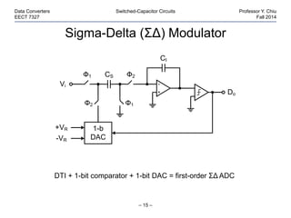
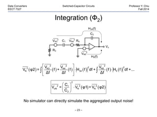
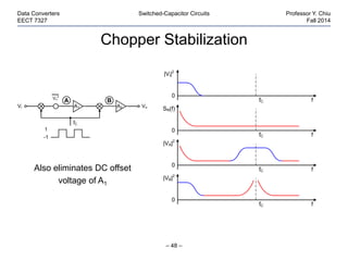
– 1 –
Data Converters Switched-Capacitor Circuits Professor Y. Chiu
EECT 7327 Fall 2014
Switched-Capacitor Circuits
Continuous-Time Integrator
– 2 –
Data Converters Switched-Capacitor Circuits Professor Y. Chiu
EECT 7327 Fall 2014
Goal:
C2
Vi
Vo
R1
C2
Vi
Vo
SC
   
   
 
 
 

t
o in
1 2 -∞
o
i 1 2
1
v t = - v ξ dξ
R C
V 1 1
H s = s = -
V R C s
Approach: emulating resistors with switched capacitors
 1 2=R C
Concept of Switched Capacitor
– 3 –
Data Converters Switched-Capacitor Circuits Professor Y. Chiu
EECT 7327 Fall 2014
 A B
q C
i = = V - V
T T

 A B
1
i = V - V
R
Ф2
Ф1
eq
T
R =
C
• A switched capacitor is a discrete-time “resistor”
• RC time constant set by capacitor ratio C2/C1 (match considerably better
than R and C) and clock period T (flexibility)
R
VA VB
i
C Ф2Ф2
Ф1Ф1
VA VB
<i>
so,
 
    
 
2
eq,1 2 2
1 1
CT
=R C = C = T
C C
Non-overlapping
two-phase clock
Switched Capacitors
– 4 –
Data Converters Switched-Capacitor Circuits Professor Y. Chiu
EECT 7327 Fall 2014
Ф1 Ф2 Ф1 Ф2 Ф1 Ф2
• Shunt- and series-type SCs are simple and cheap to implement
• Stray-insensitive SC requires 2 more switches, what’s the advantage
besides being more flexible (i.e., w/ or w/o the T/2 delay)?
2-phase clock
Ф2Ф1
VA VB
CФ1
VA VB
C Ф2
Series-typeShunt-type
C Ф2Ф2(Ф1)
Ф1Ф1(Ф2)
VA VB
Stray-insensitive
Discrete-Time Integrator (DTI)
– 5 –
Data Converters Switched-Capacitor Circuits Professor Y. Chiu
EECT 7327 Fall 2014
2-phase clock
C2
Vi
Vo
Ф2Ф1
C1
Series-typeShunt-type
Ф1 Ф2 Ф1 Ф2 Ф1 Ф2
What are the VTFs (z-domain) of these DTIs, assuming no parasitic
capacitance is present?
C2
Vi
Vo
C1Ф1
Ф2
Shunt-Type DTI
– 6 –
Data Converters Switched-Capacitor Circuits Professor Y. Chiu
EECT 7327 Fall 2014
Ф1
(sample)
Charge conservation law (ideal):
Total charge on C1 and C2 during Ф1→ Ф2 transition must remain unchanged!
C2
Vi
Vo
C1
C2
Vo
C1
Vi
Ф2
(update)

Ф1 Ф2 Ф1 Ф2 Ф1 Ф2
T
vi(t)
0 t
vo(t)
0 t
(n-1)
(n)
(n+1)
(n-1)
(n)
(n+1)
Shunt-Type DTI
– 7 –
Data Converters Switched-Capacitor Circuits Professor Y. Chiu
EECT 7327 Fall 2014
Ф1
(sample)
Ф2
(update)
C2
Vi
Vo
C1
C2
Vo
C1
Vi
      1 i 1 o 2Q φ = V n C - V n C     2 1 o 2Q φ = 0 C - V n+1 C

          1 2 i 1 o 2 1 o 2Q φ = Q φ ⇒ V n C - V n C = 0 C - V n+1 C
     i 1 o 2 o 2V z C - V z C = -z V z C
 
 
 
-1 -1/2
o 1 1
-1 -1
i 2 2
V z C Cz z
H z = = - or -
V z C 1- z C 1- z
Series-Type DTI
– 8 –
Data Converters Switched-Capacitor Circuits Professor Y. Chiu
EECT 7327 Fall 2014
Ф1
(sample/update)
Ф2
(reset C1)
C2
Vi
Vo
C1Ф1
Ф2
 
 
 
o 1
-1
i 2
V z C 1
H z = = -
V z C 1- z
VTF:
Ф1 Ф2 Ф1 Ф2 Ф1 Ф2
T
vi(t)
0 t
vo(t)
0 t
(n-1)
(n)
(n+1)
(n-1)
(n)
(n+1)
Stray Capacitance
– 9 –
Data Converters Switched-Capacitor Circuits Professor Y. Chiu
EECT 7327 Fall 2014
Series-typeShunt-type
Cu
Cu Cu
Cu Cu
C1 C2
• Strays derive from D/S diodes and
wiring capacitance
• VTF is modified due to strays
• Strays at the summing node is of no
significance (virtual ground)
2
1
C
= 4
C
C2
Vi
Vo
C1
Ф1 Ф2
A
C2
Vi
Vo
C1
Ф1
Ф2
A
Stray-Insensitive SC Integrator
– 10 –
Data Converters Switched-Capacitor Circuits Professor Y. Chiu
EECT 7327 Fall 2014
  1
-1
2
C 1
H z = -
C 1- z
VTF:
 
-1
1
-1
2
C z
H z = +
C 1- z
• Capacitors can be significantly sized down to save power/area
• Sizes are eventually limited by kT/C noise, mismatch, etc.
C1 Ф2Ф2(Ф1)
Ф1Ф1(Ф2)
C2
Vi
Vo
A B
“Inverting” “Non-inverting”
VTF:
SC Amplifier
– 11 –
Data Converters Switched-Capacitor Circuits Professor Y. Chiu
EECT 7327 Fall 2014
   -11
2
C
H z = + z
C
• Non-integrating, memoryless (less the delay)
• Used in many applications of parametric amplification
VTF:
Vi
C2
C1Ф1
Ф2
Ф1
Vo
– 12 –
Data Converters Switched-Capacitor Circuits Professor Y. Chiu
EECT 7327 Fall 2014
SC Applications
CT Filter
– 13 –
Data Converters Switched-Capacitor Circuits Professor Y. Chiu
EECT 7327 Fall 2014
R
CVi Vo
L
R1
CA
R
R
R3
R4
CB
R2
Vi
Vo
RLC prototype
Active-RC
Tow-Thomas
CT biquad

SC DT Filter
– 14 –
Data Converters Switched-Capacitor Circuits Professor Y. Chiu
EECT 7327 Fall 2014
SC DT
biquad
CA CB
Vi
Vo
C1 Ф2Ф2
Ф1Ф1
C2
C4 Ф2
Ф1
C3 Ф2Ф1
Ф1Ф2
Ф2
R1
CA
R
R
R3
R4
CB
R2
Vi
Vo
Active-RC
Tow-Thomas
CT biquad

Sigma-Delta (ΣΔ) Modulator
– 15 –
Data Converters Switched-Capacitor Circuits Professor Y. Chiu
EECT 7327 Fall 2014
CI
Ф2Ф1
Ф1Ф2
Vi
Do
+VR 1-b
DAC-VR
CS
DTI + 1-bit comparator + 1-bit DAC = first-order ΣΔ ADC
Pipelined ADC
– 16 –
Data Converters Switched-Capacitor Circuits Professor Y. Chiu
EECT 7327 Fall 2014
SC amplifier + 2 comparators + 3-level DAC = 1.5-bit pipelined ADC
Vo
Vi
0
-VR
VR
1.5-b
DAC
Φ1 C1
Φ1 C2
Φ2
Φ1
Φ2
-VR/4
VR/4
SC Common-Mode Feedback
– 17 –
Data Converters Switched-Capacitor Circuits Professor Y. Chiu
EECT 7327 Fall 2014
Vo
+
Vo
-
R
A
R
VBias Vcm
Vcmc
Vo
+
Vo
-
R
A
R
Vcmc
Vcm-VBias

CM sense amp can be replaced by a floating voltage source since the gain
through the main op-amp is high enough.
SC Common-Mode Feedback
– 18 –
Data Converters Switched-Capacitor Circuits Professor Y. Chiu
EECT 7327 Fall 2014

Vo
+
Vo
-
A
Vcmc
C
C
0.2C
0.2C
Ф2
Ф2
Ф2
Ф1
Ф1
Ф1
Vcm
Vcm
VBias
Vo
+
Vo
-
A
Vcmc
Vcm-VBias
Vcm-VBias
Ф2
Ф1
– 19 –
Data Converters Switched-Capacitor Circuits Professor Y. Chiu
EECT 7327 Fall 2014
Noise in SC Circuits
Noise of CT Integrator
– 20 –
Data Converters Switched-Capacitor Circuits Professor Y. Chiu
EECT 7327 Fall 2014
Noise in CT circuits can be simulated with SPICE (.noise)
R
C
Vi
Vo
R
C
Vo
VN1
2
VN2
2
H1(f)
H2(f)
         
2 2
2 22 N1 N2
oN 1 2
V V
V = f H f df + f H f df +...
Δf Δf
Noise of SC Integrator
– 21 –
Data Converters Switched-Capacitor Circuits Professor Y. Chiu
EECT 7327 Fall 2014
SC circuits are NOT noise-free! Switches and op-amps introduce noise.
Ф1 Ф2 Ф1 Ф2 Ф1 Ф2
C2
C1 Ф2Ф1
Ф1Ф2
Vi
Vo
Sampling (Ф1) Ideal Voltage Source
– 22 –
Data Converters Switched-Capacitor Circuits Professor Y. Chiu
EECT 7327 Fall 2014
• Noise is indistinguishable from signal after sampling
• The noise acquired by C1 will be amplified in Ф2 just like signal
       
 
 
 
 
  



2 2
∞ 22 N1 N2
N 10
2
∞
1 20
1 2
V V
V φ1 = f + f H f df
Δf Δf
1
= 4kTR +4kTR df
1+ j2πf R +R C
kT
=
C
C1
Vi
R1
R2
VN1
2
VN2
2
Integration (Ф2)
– 23 –
Data Converters Switched-Capacitor Circuits Professor Y. Chiu
EECT 7327 Fall 2014
No simulator can directly simulate the aggregated output noise!
           
 
  
  
 
2 22
2 22 N3 N5N4
N 34 5
V VV
V φ2 = f + f H f df + f H f df +...
Δf Δf Δf
   
 
 
 
2
2 2 21
oN N N
2
C
V = V φ1 + V φ2
C
Vo
VN3
2
VN5
2
H34(f)
H5(f)
C1
C2
R4VN4
2
R3
Sampling (Ф1) Noise – Cascaded Stages
– 24 –
Data Converters Switched-Capacitor Circuits Professor Y. Chiu
EECT 7327 Fall 2014
C1'R1
R2
VN3
2
VN5
2
VN1
2
VN2
2
C1
C2
R4VN4
2
R3
• Finite op-amp BW limits the noise bandwidth, resulting in less overall kT/C noise
(noise filtering).
• But parasitic loop delay may introduce peaking in freq. response, resulting in more
integrated noise (noise peaking).
C2 C2'
Vi
Vo
C1 Ф1Ф2
Ф2Ф1
C1' Ф2Ф1
Ф1Ф2
Ф2

Sampled Noise Spectrum
– 25 –
Data Converters Switched-Capacitor Circuits Professor Y. Chiu
EECT 7327 Fall 2014
• Total integrated noise power remains constant
• SNR remains constant
CT
DT
PSD
fs/2 fs 3/2fs
0
PSD
fs 2fs
0
Alias
– 26 –
Data Converters Switched-Capacitor Circuits Professor Y. Chiu
EECT 7327 Fall 2014
Non-ideal Effects in
SC Circuits
Non-ideal Effects in SC Circuits
– 27 –
Data Converters Switched-Capacitor Circuits Professor Y. Chiu
EECT 7327 Fall 2014
• Capacitors (poly-poly, metal-metal, MIM, MOM, sandwich, gate cap,
accumulation-mode gate cap, etc.)
– PP, MIM, and MOM are linear up to 14-16 bits (nonlinear voltage
coefficients negligible for most applications)
– Gate caps are typically good for up to 8-10 bits
• Switches (MOS transistors)
– Nonzero on-resistance (voltage dependent)
– (Nonlinear) stray capacitance added (Cgs, Cgd, Cgb, Cdb, Csb)
– Switch-induced sampling errors (charge injection, clock feedthrough,
junction leakage, drain-source leakage, and gate leakage)
• Operational amplifiers
– Offset
– Finite-gain effects (voltage dependent)
– Finite bandwidth and slew rate (measured by settling speed)
– 28 –
Data Converters Switched-Capacitor Circuits Professor Y. Chiu
EECT 7327 Fall 2014
Non-ideal Effects of
Switches
Nonzero On-Resistance
– 29 –
Data Converters Switched-Capacitor Circuits Professor Y. Chiu
EECT 7327 Fall 2014
• FET channel resistance (thus tracking bandwidth) depends on signal level
• Usually (RonCS)-1 ≥ (3-5)·ω-3dB of closed-loop op-amp for settling purpose
VGS
Vout
C
…
Ф
CS
Ф
Ф
CS
…
Ron
0 VDDVout
VTnVTp
PMOS
NMOS
CMOS
 -1
on ox DD th out
W
R = μC V - V - V
L
Clock Bootstrapping
– 30 –
Data Converters Switched-Capacitor Circuits Professor Y. Chiu
EECT 7327 Fall 2014
• Small on-resistance leads to large switches → large parasitic caps and
large clock buffers
• Clock bootstrapping keeps VGS of the switch constant → constant on-
resistance (body effect?) and less parasitics w/o the PMOS
Ф
Ф
CS
…
OutIn
M1
VDD
Ф1 Ф2
CMOS Bootstrapped NMOS
Simplified Clock Bootstrapper
– 31 –
Data Converters Switched-Capacitor Circuits Professor Y. Chiu
EECT 7327 Fall 2014
Pros
• Linearity
• Bandwidth
Cons
• Device reliability
• Complexity
Out
C
In
M2
M1
VDD
VSS
OutIn
M1
VDD
Ф1 Ф2
Ф1
Ф1
Ф2
Ф2
Ф2
Ф2
Switch-Induced Errors
– 32 –
Data Converters Switched-Capacitor Circuits Professor Y. Chiu
EECT 7327 Fall 2014
Channel charge injection and clock feedthrough (on drain side) result in
charge trapped on CS after switch is turned off.
Vout
Ф
CS
Zi
Vin
CgdCgs
Qch
• Clock feedthrough
• Charge injection
Clock Feedthrough and Charge Injection
– 33 –
Data Converters Switched-Capacitor Circuits Professor Y. Chiu
EECT 7327 Fall 2014
• Both phenomena sensitive to Zi, CS, and clock rise/fall time
• Offset, gain error, and nonlinearity introduced to the sampling
• Clock feedthrough can be simulated by SPICE, but charge injection
cannot be simulated with lumped transistor models
Ф
VDD
0
Vin+Vth
Switch on Switch off
Vout
Ф
CS
Zi
Vin
CgdCgs
Qch
Clock Rise/Fall-Time Dependence
– 34 –
Data Converters Switched-Capacitor Circuits Professor Y. Chiu
EECT 7327 Fall 2014
Ф
VDD
0
Vin+Vth
Switch on Switch off
Vout
Ф
CS
Zi
Vin
CgdCgs
Qch
Clock feedthrough Charge injection
Fast turn-off
Slow turn-off
gs
DD
gs S
C
ΔV = - V
C +C
 
 
ox DD th in
gs S
C WL V - V - V
ΔV = -
2 C +C
 gs
in th
gs S
C
ΔV = - V + V
C +C
ΔV = 0
Dummy Switch
– 35 –
Data Converters Switched-Capacitor Circuits Professor Y. Chiu
EECT 7327 Fall 2014
• Difficult to achieve precise cancellation due to the nonlinear
dependence of ΔV on Zi, CS, and clock rise/fall time
• Sensitive to the phase alignment between Ф and Ф_
Vout
Ф
W
L CS
W
2L
Ф
Vin
CMOS Switch
– 36 –
Data Converters Switched-Capacitor Circuits Professor Y. Chiu
EECT 7327 Fall 2014
• Very sensitive to phase alignment between Ф and Ф_
• Subject to threshold mismatch between PMOS and NMOS
• Exact cancellation occurs only for one specific Vin (which one?)
Vout
CS
Vin
Ф
Ф
Same size for
P and N FETs
Differential Signaling
– 37 –
Data Converters Switched-Capacitor Circuits Professor Y. Chiu
EECT 7327 Fall 2014
• Signal-independent errors (offset) and even-order distortions cancelled
• Gain error and odd-order nonlinearities remain
Balanced diff. input
Vop
CSp
Vip
M1
Von
CSn
Vin
M2
Ф
Ф
Switch Performance
– 38 –
Data Converters Switched-Capacitor Circuits Professor Y. Chiu
EECT 7327 Fall 2014
    ch
2
ithDDox
2
ithDDox
on
μQ
L
VVVWLμC
L
VVV
L
W
μC
1
R 




S
ch
C
Q
2
1
ΔV Charge injection:
Bandwidth:
S
2
ch
Son CL
μQ
CR
1
BW 

2 2
ch S
S ch
Q L CΔV 1 L
≈ =
BW 2 C μQ 2μ
Performance FoM:
Technology scaling improves switch performance!
On-resistance:
Leakage in SC Circuits
– 39 –
Data Converters Switched-Capacitor Circuits Professor Y. Chiu
EECT 7327 Fall 2014
• I1 – diode leakage (existing in the old days too)
• I2 – sub-threshold drain-source leakage of summing-node switch
• I3 – gate leakage (FN tunneling) of amplifier input transistors
• Leakage currents are highly temperature- and process-dependent; the
lower limit of clock frequency is often determined by leakage
Vo(t)
0 t
Ф1 Ф1Ф2 Ф2
Φ1 = “high”, Φ2 = “low”
Vi
Vo
C2
C1
A0
Vx
Ф2 Ф2
Ф1 Ф1
VB
I2 I1
I3
DS Leakage
– 40 –
Data Converters Switched-Capacitor Circuits Professor Y. Chiu
EECT 7327 Fall 2014
M1
+
Vi
+
Vo
+
Vo
-
Vi
-
CS
+
CS
-
VDD
M1
-
VDD
Ф1
Ф1e
Ф1 Ф1e
Ф2
Ф2
CS
+
CS
-
Ф2e
Ф2e
• 0.13-μm CMOS
• A0 = Gm·Ro = 90dB
• Ro ≈ 2MΩ
• Rleak ≈ 0.6V/3μA
≈ 0.2MΩ
• A0 = Gm·(Rleak//Ro)
≈ 70dB
OutIn
M1
VDD
Φ Φ
Φ
Out
Φ
Φ
Φ
Φ
Φ
Φ
Φ
In
M3 M4
M2
M1
Ileak
VDD = 1.2V
VSS = 0V
Gate Leakage
– 41 –
Data Converters Switched-Capacitor Circuits Professor Y. Chiu
EECT 7327 Fall 2014
• Direct tunneling through the thin gate oxide
• Short-channel MOSFET behaves increasingly like BJT’s
• Violates the high-impedance assumption of the summing node
    GS ox GSI ∝ WL exp -t exp V
Switch Size Optimization
– 42 –
Data Converters Switched-Capacitor Circuits Professor Y. Chiu
EECT 7327 Fall 2014
• To minimize switch-induced error voltages, small transistor size,
slow turn-off, low source impedance should be used.
• For fast settling (high-speed design), large W/L should be used, and
errors will be inevitably large as well.
Guidelines
• Always use minimum channel length for switches as long as
leakage allows.
• For a given speed, switch sizes can be optimized w/ simulation.
• Be aware of the limitations of simulators (SPICE etc.) using lumped
device models.
– 43 –
Data Converters Switched-Capacitor Circuits Professor Y. Chiu
EECT 7327 Fall 2014
Non-ideal Effects of
Op-Amps
Non-ideal Effects of Op-Amps
– 44 –
Data Converters Switched-Capacitor Circuits Professor Y. Chiu
EECT 7327 Fall 2014
• Offset
• Finite-gain effects (voltage dependent)
• Finite bandwidth and slew rate (measured by settling
speed)
Offset Voltage
– 45 –
Data Converters Switched-Capacitor Circuits Professor Y. Chiu
EECT 7327 Fall 2014
        1 i 1 o os 2Q φ = V n C + V n - V C
      2 os 1 o os 2Q φ = -V C + V n+1 - V C
   
-1
1
o i-1
2
C z
V z = V z
C 1- z
Vi
Vo
C2
C1Ф1
Ф2
Ф2
Ф1 Vos
Vo(t)
0 t
Ф1 Ф1Ф2 Ф2
Vi = 0
   
 
 
 
1
i o o os
2
C
V = 0 ⇒ V n+1 - V n = V
C
Autozeroing
– 46 –
Data Converters Switched-Capacitor Circuits Professor Y. Chiu
EECT 7327 Fall 2014
      1 i os 1 os 2Q φ = V n - V C - V C
      2 os 1 o os 2Q φ = -V C + V n - V C
 
 
 
o 1
i 2
V z C
H z = =
V z C
Vi
Vo
C2
C1Ф1
Ф2
Ф2
Ф1
Vos
Ф1
• Also eliminates low-frequency noise, e.g., 1/f noise
• A.k.a. correlated double sampling (CDS)
Chopper Stabilization
– 47 –
Data Converters Switched-Capacitor Circuits Professor Y. Chiu
EECT 7327 Fall 2014
Ref: K. C. Hsieh, P. R. Gray, D. Senderowicz, and D. G. Messerschmitt, “A low-noise
chopper-stabilized differential switched-capacitor filtering technique,” IEEE Journal of
Solid-State Circuits, vol. 16, issue 6, pp. 708-715, 1981.
Vi VoA1
Vn
2
A2
fC
1
-1
A B
Chopper Stabilization
– 48 –
Data Converters Switched-Capacitor Circuits Professor Y. Chiu
EECT 7327 Fall 2014
Also eliminates DC offset
voltage of A1
Vi VoA1
Vn
2
A2
fC
1
-1
A B
|Vi|2
f
0
SN(f)
f
0
f
0
|VA|2
|VB|2
f
0
fC
fC
fC
fC
Chopper-Stabilized Differential Op-Amp
– 49 –
Data Converters Switched-Capacitor Circuits Professor Y. Chiu
EECT 7327 Fall 2014
Vi+
Vi-
Vo-
Vo+
Ф
Ф
Ф
Ф
Ф
Ф
Ф
Ф
• Integrators/amplifiers can be built using these op-amps
• Some oversampling is useful to facilitate the implementation
Ideal SC Amplifier
– 50 –
Data Converters Switched-Capacitor Circuits Professor Y. Chiu
EECT 7327 Fall 2014
1
CL
2
C
A =
C
• Closed-loop gain is determined by the capacitor ratio by design
• But this is assuming X is an ideal summing node (the op-amp is ideal)
Vi
∞
C2
C1Ф1
Ф2
Ф1
VoX
Finite-Gain Effect in SC Amplifier
– 51 –
Data Converters Switched-Capacitor Circuits Professor Y. Chiu
EECT 7327 Fall 2014
 
  
 
o 1 1 1 2
CL
1 2i 2 2 2
2
V C C C +C1
A = = ≈ 1-
C +CV C C C A1+
C A
Vi
A
C2
C1Ф1
Ф2
Ф1
VoX
     
     
   

 1 i 1 x 1 1 2
x 1 o 1 x 1
Q φ = V φ - V φ C +0 C
V φ = V φ = -V φ A
        1 2 i 1 x 1 o x 2Q φ = Q φ ⇒ V C = -V C + V - V C
       
   
   

 2 x 2 1 o 2 x 2 2
o 2 x 2
Q φ = -V φ C + V φ - V φ C
V φ = -V φ A
o xV = -V A
– 52 –
Data Converters Switched-Capacitor Circuits Professor Y. Chiu
EECT 7327 Fall 2014
Practical Issues
Analog vs. Digital Supply Lines
– 53 –
Data Converters Switched-Capacitor Circuits Professor Y. Chiu
EECT 7327 Fall 2014
Sharing sensitive analog supplies with digital ones is a very bad idea.
Analog
circuits
Digital
circuits
Pad
Pad
VDD CBP
id=
d
L
di
ΔV =L
dt
R dΔV =i R
A DD L RV = V - ΔV - ΔV
Analog vs. Digital Supply Lines
– 54 –
Data Converters Switched-Capacitor Circuits Professor Y. Chiu
EECT 7327 Fall 2014
• Dedicated pads
for analog and
digital supplies
• On-chip bypass
capacitors help
(watch ringing)
• Off-chip chokes
(large inductors)
can stop noise
propagation at
board level
Analog
circuits
Digital
circuits
Pad
Pad
VDD CBP
Pad
Pad
id=
“Supply” Capacitance
– 55 –
Data Converters Switched-Capacitor Circuits Professor Y. Chiu
EECT 7327 Fall 2014
• Any summing-node stray capacitance can be a potential coupling path.
• VDD, VSS, substrate, clock line, and digital noises, body effect, etc.
• Fully differential circuits help to reject common-mode noise and coupling.
Cp
…
VDD
VSS
M2
M5
M3 M4
M7
M6
Vo
CC
Vi
C2
C1Ф1
Ф2
Ф2
Ф1
M1
S
Y
X
Cgs
Cgd
 stray
o
2
C
ΔV = ΔV
C
“Supply” Capacitance
– 56 –
Data Converters Switched-Capacitor Circuits Professor Y. Chiu
EECT 7327 Fall 2014
• Avoid connecting bottom-plate parasitics to the summing node
• Avoid crossing other signal lines with the summing node
• Shielding can mitigate substrate noise coupling
n substrate
p+
p well
Cbot
C2
Clock Generation
– 57 –
Data Converters Switched-Capacitor Circuits Professor Y. Chiu
EECT 7327 Fall 2014
• Clock-gated ring structure
• Non-overlapping time determined by inverter delays, sensitive to process,
voltage, and temperature (PVT) variations
• DLL is an alternative, often used in high-speed designs
CLK Ф2
Ф1
Ф2
Ф1

Switched capacitor

  • 1.
    – 1 – DataConverters Switched-Capacitor Circuits Professor Y. Chiu EECT 7327 Fall 2014 Switched-Capacitor Circuits
  • 2.
    Continuous-Time Integrator – 2– Data Converters Switched-Capacitor Circuits Professor Y. Chiu EECT 7327 Fall 2014 Goal: C2 Vi Vo R1 C2 Vi Vo SC                t o in 1 2 -∞ o i 1 2 1 v t = - v ξ dξ R C V 1 1 H s = s = - V R C s Approach: emulating resistors with switched capacitors  1 2=R C
  • 3.
    Concept of SwitchedCapacitor – 3 – Data Converters Switched-Capacitor Circuits Professor Y. Chiu EECT 7327 Fall 2014  A B q C i = = V - V T T   A B 1 i = V - V R Ф2 Ф1 eq T R = C • A switched capacitor is a discrete-time “resistor” • RC time constant set by capacitor ratio C2/C1 (match considerably better than R and C) and clock period T (flexibility) R VA VB i C Ф2Ф2 Ф1Ф1 VA VB <i> so,          2 eq,1 2 2 1 1 CT =R C = C = T C C Non-overlapping two-phase clock
  • 4.
    Switched Capacitors – 4– Data Converters Switched-Capacitor Circuits Professor Y. Chiu EECT 7327 Fall 2014 Ф1 Ф2 Ф1 Ф2 Ф1 Ф2 • Shunt- and series-type SCs are simple and cheap to implement • Stray-insensitive SC requires 2 more switches, what’s the advantage besides being more flexible (i.e., w/ or w/o the T/2 delay)? 2-phase clock Ф2Ф1 VA VB CФ1 VA VB C Ф2 Series-typeShunt-type C Ф2Ф2(Ф1) Ф1Ф1(Ф2) VA VB Stray-insensitive
  • 5.
    Discrete-Time Integrator (DTI) –5 – Data Converters Switched-Capacitor Circuits Professor Y. Chiu EECT 7327 Fall 2014 2-phase clock C2 Vi Vo Ф2Ф1 C1 Series-typeShunt-type Ф1 Ф2 Ф1 Ф2 Ф1 Ф2 What are the VTFs (z-domain) of these DTIs, assuming no parasitic capacitance is present? C2 Vi Vo C1Ф1 Ф2
  • 6.
    Shunt-Type DTI – 6– Data Converters Switched-Capacitor Circuits Professor Y. Chiu EECT 7327 Fall 2014 Ф1 (sample) Charge conservation law (ideal): Total charge on C1 and C2 during Ф1→ Ф2 transition must remain unchanged! C2 Vi Vo C1 C2 Vo C1 Vi Ф2 (update)  Ф1 Ф2 Ф1 Ф2 Ф1 Ф2 T vi(t) 0 t vo(t) 0 t (n-1) (n) (n+1) (n-1) (n) (n+1)
  • 7.
    Shunt-Type DTI – 7– Data Converters Switched-Capacitor Circuits Professor Y. Chiu EECT 7327 Fall 2014 Ф1 (sample) Ф2 (update) C2 Vi Vo C1 C2 Vo C1 Vi       1 i 1 o 2Q φ = V n C - V n C     2 1 o 2Q φ = 0 C - V n+1 C            1 2 i 1 o 2 1 o 2Q φ = Q φ ⇒ V n C - V n C = 0 C - V n+1 C      i 1 o 2 o 2V z C - V z C = -z V z C       -1 -1/2 o 1 1 -1 -1 i 2 2 V z C Cz z H z = = - or - V z C 1- z C 1- z
  • 8.
    Series-Type DTI – 8– Data Converters Switched-Capacitor Circuits Professor Y. Chiu EECT 7327 Fall 2014 Ф1 (sample/update) Ф2 (reset C1) C2 Vi Vo C1Ф1 Ф2       o 1 -1 i 2 V z C 1 H z = = - V z C 1- z VTF: Ф1 Ф2 Ф1 Ф2 Ф1 Ф2 T vi(t) 0 t vo(t) 0 t (n-1) (n) (n+1) (n-1) (n) (n+1)
  • 9.
    Stray Capacitance – 9– Data Converters Switched-Capacitor Circuits Professor Y. Chiu EECT 7327 Fall 2014 Series-typeShunt-type Cu Cu Cu Cu Cu C1 C2 • Strays derive from D/S diodes and wiring capacitance • VTF is modified due to strays • Strays at the summing node is of no significance (virtual ground) 2 1 C = 4 C C2 Vi Vo C1 Ф1 Ф2 A C2 Vi Vo C1 Ф1 Ф2 A
  • 10.
    Stray-Insensitive SC Integrator –10 – Data Converters Switched-Capacitor Circuits Professor Y. Chiu EECT 7327 Fall 2014   1 -1 2 C 1 H z = - C 1- z VTF:   -1 1 -1 2 C z H z = + C 1- z • Capacitors can be significantly sized down to save power/area • Sizes are eventually limited by kT/C noise, mismatch, etc. C1 Ф2Ф2(Ф1) Ф1Ф1(Ф2) C2 Vi Vo A B “Inverting” “Non-inverting” VTF:
  • 11.
    SC Amplifier – 11– Data Converters Switched-Capacitor Circuits Professor Y. Chiu EECT 7327 Fall 2014    -11 2 C H z = + z C • Non-integrating, memoryless (less the delay) • Used in many applications of parametric amplification VTF: Vi C2 C1Ф1 Ф2 Ф1 Vo
  • 12.
    – 12 – DataConverters Switched-Capacitor Circuits Professor Y. Chiu EECT 7327 Fall 2014 SC Applications
  • 13.
    CT Filter – 13– Data Converters Switched-Capacitor Circuits Professor Y. Chiu EECT 7327 Fall 2014 R CVi Vo L R1 CA R R R3 R4 CB R2 Vi Vo RLC prototype Active-RC Tow-Thomas CT biquad 
  • 14.
    SC DT Filter –14 – Data Converters Switched-Capacitor Circuits Professor Y. Chiu EECT 7327 Fall 2014 SC DT biquad CA CB Vi Vo C1 Ф2Ф2 Ф1Ф1 C2 C4 Ф2 Ф1 C3 Ф2Ф1 Ф1Ф2 Ф2 R1 CA R R R3 R4 CB R2 Vi Vo Active-RC Tow-Thomas CT biquad 
  • 15.
    Sigma-Delta (ΣΔ) Modulator –15 – Data Converters Switched-Capacitor Circuits Professor Y. Chiu EECT 7327 Fall 2014 CI Ф2Ф1 Ф1Ф2 Vi Do +VR 1-b DAC-VR CS DTI + 1-bit comparator + 1-bit DAC = first-order ΣΔ ADC
  • 16.
    Pipelined ADC – 16– Data Converters Switched-Capacitor Circuits Professor Y. Chiu EECT 7327 Fall 2014 SC amplifier + 2 comparators + 3-level DAC = 1.5-bit pipelined ADC Vo Vi 0 -VR VR 1.5-b DAC Φ1 C1 Φ1 C2 Φ2 Φ1 Φ2 -VR/4 VR/4
  • 17.
    SC Common-Mode Feedback –17 – Data Converters Switched-Capacitor Circuits Professor Y. Chiu EECT 7327 Fall 2014 Vo + Vo - R A R VBias Vcm Vcmc Vo + Vo - R A R Vcmc Vcm-VBias  CM sense amp can be replaced by a floating voltage source since the gain through the main op-amp is high enough.
  • 18.
    SC Common-Mode Feedback –18 – Data Converters Switched-Capacitor Circuits Professor Y. Chiu EECT 7327 Fall 2014  Vo + Vo - A Vcmc C C 0.2C 0.2C Ф2 Ф2 Ф2 Ф1 Ф1 Ф1 Vcm Vcm VBias Vo + Vo - A Vcmc Vcm-VBias Vcm-VBias Ф2 Ф1
  • 19.
    – 19 – DataConverters Switched-Capacitor Circuits Professor Y. Chiu EECT 7327 Fall 2014 Noise in SC Circuits
  • 20.
    Noise of CTIntegrator – 20 – Data Converters Switched-Capacitor Circuits Professor Y. Chiu EECT 7327 Fall 2014 Noise in CT circuits can be simulated with SPICE (.noise) R C Vi Vo R C Vo VN1 2 VN2 2 H1(f) H2(f)           2 2 2 22 N1 N2 oN 1 2 V V V = f H f df + f H f df +... Δf Δf
  • 21.
    Noise of SCIntegrator – 21 – Data Converters Switched-Capacitor Circuits Professor Y. Chiu EECT 7327 Fall 2014 SC circuits are NOT noise-free! Switches and op-amps introduce noise. Ф1 Ф2 Ф1 Ф2 Ф1 Ф2 C2 C1 Ф2Ф1 Ф1Ф2 Vi Vo
  • 22.
    Sampling (Ф1) IdealVoltage Source – 22 – Data Converters Switched-Capacitor Circuits Professor Y. Chiu EECT 7327 Fall 2014 • Noise is indistinguishable from signal after sampling • The noise acquired by C1 will be amplified in Ф2 just like signal                       2 2 ∞ 22 N1 N2 N 10 2 ∞ 1 20 1 2 V V V φ1 = f + f H f df Δf Δf 1 = 4kTR +4kTR df 1+ j2πf R +R C kT = C C1 Vi R1 R2 VN1 2 VN2 2
  • 23.
    Integration (Ф2) – 23– Data Converters Switched-Capacitor Circuits Professor Y. Chiu EECT 7327 Fall 2014 No simulator can directly simulate the aggregated output noise!                       2 22 2 22 N3 N5N4 N 34 5 V VV V φ2 = f + f H f df + f H f df +... Δf Δf Δf           2 2 2 21 oN N N 2 C V = V φ1 + V φ2 C Vo VN3 2 VN5 2 H34(f) H5(f) C1 C2 R4VN4 2 R3
  • 24.
    Sampling (Ф1) Noise– Cascaded Stages – 24 – Data Converters Switched-Capacitor Circuits Professor Y. Chiu EECT 7327 Fall 2014 C1'R1 R2 VN3 2 VN5 2 VN1 2 VN2 2 C1 C2 R4VN4 2 R3 • Finite op-amp BW limits the noise bandwidth, resulting in less overall kT/C noise (noise filtering). • But parasitic loop delay may introduce peaking in freq. response, resulting in more integrated noise (noise peaking). C2 C2' Vi Vo C1 Ф1Ф2 Ф2Ф1 C1' Ф2Ф1 Ф1Ф2 Ф2 
  • 25.
    Sampled Noise Spectrum –25 – Data Converters Switched-Capacitor Circuits Professor Y. Chiu EECT 7327 Fall 2014 • Total integrated noise power remains constant • SNR remains constant CT DT PSD fs/2 fs 3/2fs 0 PSD fs 2fs 0 Alias
  • 26.
    – 26 – DataConverters Switched-Capacitor Circuits Professor Y. Chiu EECT 7327 Fall 2014 Non-ideal Effects in SC Circuits
  • 27.
    Non-ideal Effects inSC Circuits – 27 – Data Converters Switched-Capacitor Circuits Professor Y. Chiu EECT 7327 Fall 2014 • Capacitors (poly-poly, metal-metal, MIM, MOM, sandwich, gate cap, accumulation-mode gate cap, etc.) – PP, MIM, and MOM are linear up to 14-16 bits (nonlinear voltage coefficients negligible for most applications) – Gate caps are typically good for up to 8-10 bits • Switches (MOS transistors) – Nonzero on-resistance (voltage dependent) – (Nonlinear) stray capacitance added (Cgs, Cgd, Cgb, Cdb, Csb) – Switch-induced sampling errors (charge injection, clock feedthrough, junction leakage, drain-source leakage, and gate leakage) • Operational amplifiers – Offset – Finite-gain effects (voltage dependent) – Finite bandwidth and slew rate (measured by settling speed)
  • 28.
    – 28 – DataConverters Switched-Capacitor Circuits Professor Y. Chiu EECT 7327 Fall 2014 Non-ideal Effects of Switches
  • 29.
    Nonzero On-Resistance – 29– Data Converters Switched-Capacitor Circuits Professor Y. Chiu EECT 7327 Fall 2014 • FET channel resistance (thus tracking bandwidth) depends on signal level • Usually (RonCS)-1 ≥ (3-5)·ω-3dB of closed-loop op-amp for settling purpose VGS Vout C … Ф CS Ф Ф CS … Ron 0 VDDVout VTnVTp PMOS NMOS CMOS  -1 on ox DD th out W R = μC V - V - V L
  • 30.
    Clock Bootstrapping – 30– Data Converters Switched-Capacitor Circuits Professor Y. Chiu EECT 7327 Fall 2014 • Small on-resistance leads to large switches → large parasitic caps and large clock buffers • Clock bootstrapping keeps VGS of the switch constant → constant on- resistance (body effect?) and less parasitics w/o the PMOS Ф Ф CS … OutIn M1 VDD Ф1 Ф2 CMOS Bootstrapped NMOS
  • 31.
    Simplified Clock Bootstrapper –31 – Data Converters Switched-Capacitor Circuits Professor Y. Chiu EECT 7327 Fall 2014 Pros • Linearity • Bandwidth Cons • Device reliability • Complexity Out C In M2 M1 VDD VSS OutIn M1 VDD Ф1 Ф2 Ф1 Ф1 Ф2 Ф2 Ф2 Ф2
  • 32.
    Switch-Induced Errors – 32– Data Converters Switched-Capacitor Circuits Professor Y. Chiu EECT 7327 Fall 2014 Channel charge injection and clock feedthrough (on drain side) result in charge trapped on CS after switch is turned off. Vout Ф CS Zi Vin CgdCgs Qch • Clock feedthrough • Charge injection
  • 33.
    Clock Feedthrough andCharge Injection – 33 – Data Converters Switched-Capacitor Circuits Professor Y. Chiu EECT 7327 Fall 2014 • Both phenomena sensitive to Zi, CS, and clock rise/fall time • Offset, gain error, and nonlinearity introduced to the sampling • Clock feedthrough can be simulated by SPICE, but charge injection cannot be simulated with lumped transistor models Ф VDD 0 Vin+Vth Switch on Switch off Vout Ф CS Zi Vin CgdCgs Qch
  • 34.
    Clock Rise/Fall-Time Dependence –34 – Data Converters Switched-Capacitor Circuits Professor Y. Chiu EECT 7327 Fall 2014 Ф VDD 0 Vin+Vth Switch on Switch off Vout Ф CS Zi Vin CgdCgs Qch Clock feedthrough Charge injection Fast turn-off Slow turn-off gs DD gs S C ΔV = - V C +C     ox DD th in gs S C WL V - V - V ΔV = - 2 C +C  gs in th gs S C ΔV = - V + V C +C ΔV = 0
  • 35.
    Dummy Switch – 35– Data Converters Switched-Capacitor Circuits Professor Y. Chiu EECT 7327 Fall 2014 • Difficult to achieve precise cancellation due to the nonlinear dependence of ΔV on Zi, CS, and clock rise/fall time • Sensitive to the phase alignment between Ф and Ф_ Vout Ф W L CS W 2L Ф Vin
  • 36.
    CMOS Switch – 36– Data Converters Switched-Capacitor Circuits Professor Y. Chiu EECT 7327 Fall 2014 • Very sensitive to phase alignment between Ф and Ф_ • Subject to threshold mismatch between PMOS and NMOS • Exact cancellation occurs only for one specific Vin (which one?) Vout CS Vin Ф Ф Same size for P and N FETs
  • 37.
    Differential Signaling – 37– Data Converters Switched-Capacitor Circuits Professor Y. Chiu EECT 7327 Fall 2014 • Signal-independent errors (offset) and even-order distortions cancelled • Gain error and odd-order nonlinearities remain Balanced diff. input Vop CSp Vip M1 Von CSn Vin M2 Ф Ф
  • 38.
    Switch Performance – 38– Data Converters Switched-Capacitor Circuits Professor Y. Chiu EECT 7327 Fall 2014     ch 2 ithDDox 2 ithDDox on μQ L VVVWLμC L VVV L W μC 1 R      S ch C Q 2 1 ΔV Charge injection: Bandwidth: S 2 ch Son CL μQ CR 1 BW   2 2 ch S S ch Q L CΔV 1 L ≈ = BW 2 C μQ 2μ Performance FoM: Technology scaling improves switch performance! On-resistance:
  • 39.
    Leakage in SCCircuits – 39 – Data Converters Switched-Capacitor Circuits Professor Y. Chiu EECT 7327 Fall 2014 • I1 – diode leakage (existing in the old days too) • I2 – sub-threshold drain-source leakage of summing-node switch • I3 – gate leakage (FN tunneling) of amplifier input transistors • Leakage currents are highly temperature- and process-dependent; the lower limit of clock frequency is often determined by leakage Vo(t) 0 t Ф1 Ф1Ф2 Ф2 Φ1 = “high”, Φ2 = “low” Vi Vo C2 C1 A0 Vx Ф2 Ф2 Ф1 Ф1 VB I2 I1 I3
  • 40.
    DS Leakage – 40– Data Converters Switched-Capacitor Circuits Professor Y. Chiu EECT 7327 Fall 2014 M1 + Vi + Vo + Vo - Vi - CS + CS - VDD M1 - VDD Ф1 Ф1e Ф1 Ф1e Ф2 Ф2 CS + CS - Ф2e Ф2e • 0.13-μm CMOS • A0 = Gm·Ro = 90dB • Ro ≈ 2MΩ • Rleak ≈ 0.6V/3μA ≈ 0.2MΩ • A0 = Gm·(Rleak//Ro) ≈ 70dB OutIn M1 VDD Φ Φ Φ Out Φ Φ Φ Φ Φ Φ Φ In M3 M4 M2 M1 Ileak VDD = 1.2V VSS = 0V
  • 41.
    Gate Leakage – 41– Data Converters Switched-Capacitor Circuits Professor Y. Chiu EECT 7327 Fall 2014 • Direct tunneling through the thin gate oxide • Short-channel MOSFET behaves increasingly like BJT’s • Violates the high-impedance assumption of the summing node     GS ox GSI ∝ WL exp -t exp V
  • 42.
    Switch Size Optimization –42 – Data Converters Switched-Capacitor Circuits Professor Y. Chiu EECT 7327 Fall 2014 • To minimize switch-induced error voltages, small transistor size, slow turn-off, low source impedance should be used. • For fast settling (high-speed design), large W/L should be used, and errors will be inevitably large as well. Guidelines • Always use minimum channel length for switches as long as leakage allows. • For a given speed, switch sizes can be optimized w/ simulation. • Be aware of the limitations of simulators (SPICE etc.) using lumped device models.
  • 43.
    – 43 – DataConverters Switched-Capacitor Circuits Professor Y. Chiu EECT 7327 Fall 2014 Non-ideal Effects of Op-Amps
  • 44.
    Non-ideal Effects ofOp-Amps – 44 – Data Converters Switched-Capacitor Circuits Professor Y. Chiu EECT 7327 Fall 2014 • Offset • Finite-gain effects (voltage dependent) • Finite bandwidth and slew rate (measured by settling speed)
  • 45.
    Offset Voltage – 45– Data Converters Switched-Capacitor Circuits Professor Y. Chiu EECT 7327 Fall 2014         1 i 1 o os 2Q φ = V n C + V n - V C       2 os 1 o os 2Q φ = -V C + V n+1 - V C     -1 1 o i-1 2 C z V z = V z C 1- z Vi Vo C2 C1Ф1 Ф2 Ф2 Ф1 Vos Vo(t) 0 t Ф1 Ф1Ф2 Ф2 Vi = 0           1 i o o os 2 C V = 0 ⇒ V n+1 - V n = V C
  • 46.
    Autozeroing – 46 – DataConverters Switched-Capacitor Circuits Professor Y. Chiu EECT 7327 Fall 2014       1 i os 1 os 2Q φ = V n - V C - V C       2 os 1 o os 2Q φ = -V C + V n - V C       o 1 i 2 V z C H z = = V z C Vi Vo C2 C1Ф1 Ф2 Ф2 Ф1 Vos Ф1 • Also eliminates low-frequency noise, e.g., 1/f noise • A.k.a. correlated double sampling (CDS)
  • 47.
    Chopper Stabilization – 47– Data Converters Switched-Capacitor Circuits Professor Y. Chiu EECT 7327 Fall 2014 Ref: K. C. Hsieh, P. R. Gray, D. Senderowicz, and D. G. Messerschmitt, “A low-noise chopper-stabilized differential switched-capacitor filtering technique,” IEEE Journal of Solid-State Circuits, vol. 16, issue 6, pp. 708-715, 1981. Vi VoA1 Vn 2 A2 fC 1 -1 A B
  • 48.
    Chopper Stabilization – 48– Data Converters Switched-Capacitor Circuits Professor Y. Chiu EECT 7327 Fall 2014 Also eliminates DC offset voltage of A1 Vi VoA1 Vn 2 A2 fC 1 -1 A B |Vi|2 f 0 SN(f) f 0 f 0 |VA|2 |VB|2 f 0 fC fC fC fC
  • 49.
    Chopper-Stabilized Differential Op-Amp –49 – Data Converters Switched-Capacitor Circuits Professor Y. Chiu EECT 7327 Fall 2014 Vi+ Vi- Vo- Vo+ Ф Ф Ф Ф Ф Ф Ф Ф • Integrators/amplifiers can be built using these op-amps • Some oversampling is useful to facilitate the implementation
  • 50.
    Ideal SC Amplifier –50 – Data Converters Switched-Capacitor Circuits Professor Y. Chiu EECT 7327 Fall 2014 1 CL 2 C A = C • Closed-loop gain is determined by the capacitor ratio by design • But this is assuming X is an ideal summing node (the op-amp is ideal) Vi ∞ C2 C1Ф1 Ф2 Ф1 VoX
  • 51.
    Finite-Gain Effect inSC Amplifier – 51 – Data Converters Switched-Capacitor Circuits Professor Y. Chiu EECT 7327 Fall 2014        o 1 1 1 2 CL 1 2i 2 2 2 2 V C C C +C1 A = = ≈ 1- C +CV C C C A1+ C A Vi A C2 C1Ф1 Ф2 Ф1 VoX                   1 i 1 x 1 1 2 x 1 o 1 x 1 Q φ = V φ - V φ C +0 C V φ = V φ = -V φ A         1 2 i 1 x 1 o x 2Q φ = Q φ ⇒ V C = -V C + V - V C                   2 x 2 1 o 2 x 2 2 o 2 x 2 Q φ = -V φ C + V φ - V φ C V φ = -V φ A o xV = -V A
  • 52.
    – 52 – DataConverters Switched-Capacitor Circuits Professor Y. Chiu EECT 7327 Fall 2014 Practical Issues
  • 53.
    Analog vs. DigitalSupply Lines – 53 – Data Converters Switched-Capacitor Circuits Professor Y. Chiu EECT 7327 Fall 2014 Sharing sensitive analog supplies with digital ones is a very bad idea. Analog circuits Digital circuits Pad Pad VDD CBP id= d L di ΔV =L dt R dΔV =i R A DD L RV = V - ΔV - ΔV
  • 54.
    Analog vs. DigitalSupply Lines – 54 – Data Converters Switched-Capacitor Circuits Professor Y. Chiu EECT 7327 Fall 2014 • Dedicated pads for analog and digital supplies • On-chip bypass capacitors help (watch ringing) • Off-chip chokes (large inductors) can stop noise propagation at board level Analog circuits Digital circuits Pad Pad VDD CBP Pad Pad id=
  • 55.
    “Supply” Capacitance – 55– Data Converters Switched-Capacitor Circuits Professor Y. Chiu EECT 7327 Fall 2014 • Any summing-node stray capacitance can be a potential coupling path. • VDD, VSS, substrate, clock line, and digital noises, body effect, etc. • Fully differential circuits help to reject common-mode noise and coupling. Cp … VDD VSS M2 M5 M3 M4 M7 M6 Vo CC Vi C2 C1Ф1 Ф2 Ф2 Ф1 M1 S Y X Cgs Cgd  stray o 2 C ΔV = ΔV C
  • 56.
    “Supply” Capacitance – 56– Data Converters Switched-Capacitor Circuits Professor Y. Chiu EECT 7327 Fall 2014 • Avoid connecting bottom-plate parasitics to the summing node • Avoid crossing other signal lines with the summing node • Shielding can mitigate substrate noise coupling n substrate p+ p well Cbot C2
  • 57.
    Clock Generation – 57– Data Converters Switched-Capacitor Circuits Professor Y. Chiu EECT 7327 Fall 2014 • Clock-gated ring structure • Non-overlapping time determined by inverter delays, sensitive to process, voltage, and temperature (PVT) variations • DLL is an alternative, often used in high-speed designs CLK Ф2 Ф1 Ф2 Ф1