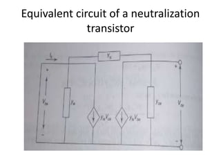
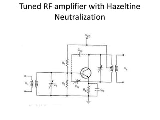
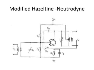
Neutralization
• Technique used for the elimination of
potential oscillation is called neutralization
• BJT and FET are potentially unstable over
some frequency range due to feedback
parameter(YN ) present in them.
• Feedback can be cancelled by an additional
feedback signal
• That is equal in amplitude and opposite in
sign.
Equivalent circuit of a neutralization
transistor
• Yre
‘ = Ib / Vce by making Vbe = 0
• Ib = Yre Vce- YN Vce
• Yre
‘= Yre - YN
• For perfect neutralization, Yre
‘ = 0
• Therefore Yre = YN
• desired component used for neutralization is
Negative capacitor
Tuned RF amplifier with Hazeltine
Neutralization
• Hazeltine technique is used to maintain
Stability
• Undesire effect of collector to base
capacitance is neutralize by introducing a
signal which cancels the signal.
• CN - Variable capacitor
• CN - connected from bottom of the coil
• It introduces a signal to base of transistor
such that it cancels the signal Cbc.
Modified Hazeltine -Neutrodyne
• Modified version of hazeltine
neutralization called Neutrodyne
neutralization technique.
• CN is connected to the lower end of
secondary coil of next stage.
• Hence it is connected with VCC, It is
insesitive to any variation in supply
voltage
• It provides higher stabilization for the
tuned amplifier
Advantages
• Amplify defined frequencies
• Signal to noise at output is good
• Suited for radio transmitter and receiver
Disadvantages
• Circuit is bulky because of inductors and
capacitors
• Circuit is Costly
• Design become complex if band frequency
increases
• Not suitable to amplify audio frequency

Neutralization Technique in EDC

  • 1.
  • 2.
    • Technique usedfor the elimination of potential oscillation is called neutralization • BJT and FET are potentially unstable over some frequency range due to feedback parameter(YN ) present in them. • Feedback can be cancelled by an additional feedback signal • That is equal in amplitude and opposite in sign.
  • 3.
    Equivalent circuit ofa neutralization transistor
  • 4.
    • Yre ‘ =Ib / Vce by making Vbe = 0 • Ib = Yre Vce- YN Vce • Yre ‘= Yre - YN • For perfect neutralization, Yre ‘ = 0 • Therefore Yre = YN • desired component used for neutralization is Negative capacitor
  • 5.
    Tuned RF amplifierwith Hazeltine Neutralization
  • 6.
    • Hazeltine techniqueis used to maintain Stability • Undesire effect of collector to base capacitance is neutralize by introducing a signal which cancels the signal. • CN - Variable capacitor • CN - connected from bottom of the coil • It introduces a signal to base of transistor such that it cancels the signal Cbc.
  • 7.
  • 8.
    • Modified versionof hazeltine neutralization called Neutrodyne neutralization technique. • CN is connected to the lower end of secondary coil of next stage. • Hence it is connected with VCC, It is insesitive to any variation in supply voltage • It provides higher stabilization for the tuned amplifier
  • 9.
    Advantages • Amplify definedfrequencies • Signal to noise at output is good • Suited for radio transmitter and receiver
  • 10.
    Disadvantages • Circuit isbulky because of inductors and capacitors • Circuit is Costly • Design become complex if band frequency increases • Not suitable to amplify audio frequency