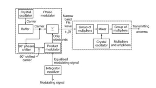
9. Armstrong Method for the Generation
of FM
• In the direct methods of generation of FM, LC oscillators are to
be used. The crystal oscillator cannot be used. The LC
oscillators are not stable enough for the communication or
broadcast purpose. Thus, the direct methods cannot be used
for the broadcast applications.
• The alternative method is to use the indirect method called as
the Armstrong method of FM generation.
• In this method, the FM is obtained through phase modulation.
• A crystal oscillator can be used hence the frequency stability is
very high and this method is widely used in practice.
10.
11. • The Armstrong method uses the phase modulator to generate a
frequency modulated wave.
• Working Principle
• The working operation of this system can be divided into two
parts as follows:
• Part I: Generate a narrow band FM wave using a phase
modulator.
• Part II: Use the frequency multipliers and mixer to obtain
the required values of frequency deviation, carrier and
modulation index.
12. Part I: Generate a narrow band FM using
Phase Modulator
• As discussed carrier, we can generate FM using a phase
modulator.
• The modulating signal x(t) is passed through an integrator
before applying it to the phase modulator as shown in figure
• Let the narrow band FM wave produced at the output of the
phase modulator be represented by s1(t) i.e.,
13. • where Vc1 is the amplitude and f1 is the frequency of the carrier
produced by the crystal oscillator.
• The phase angle Φ1(t) of s1(t) is related to x(t) as follows:
• where k1 represents the frequency sensitivity of the modulator.
• If Φ1(t) is very small then,
16. Working Principle
• The crystal oscillator produces a stable unmodulated carrier
which is applied to the 90° phase shifter as well as the
combining network through a buffer.
• The 90° phase shifter produces a 90° phase shifted carrier. It is
applied to the balanced modulator along with the modulating
signal.
• Thus, the carrier used for modulation is 90° shifted with respect
to the original carrier.
• At the output of the product modulator, we get DSB SC signal
i.e., AM signal without carrier.
17. • This signal consists of only two sidebands with their resultant in
phase with the 90° shifted carrier .
• The two sidebands and the original carrier without any phase
shift are applied to a combining network (∑). At the output of the
combining network, we get the resultant of vector addition of the
carrier and two sidebands as shown in figure
18. • Now, as the modulation index is increased, the amplitude of
sidebands will also increase. Hence, the amplitude of their
resultant increases. This will increase the angle Φ made by the
resultant with unmodulated carrier.
• The angle Φ decreases with reduction in modulation index as
shown in figure
19. • Thus, the resultant at the output of the combining network is
phase modulated. Hence, the block diagram of figure.1
operates as a phase modulator.
• Part III: Use of Frequency Multipliers Mixer and Amplifier
• The FM signal produced at the output of phase modulator has a
low carrier frequency and low modulation index. They are
increased to an adequately high value with the help of
frequency multipliers and mixer.