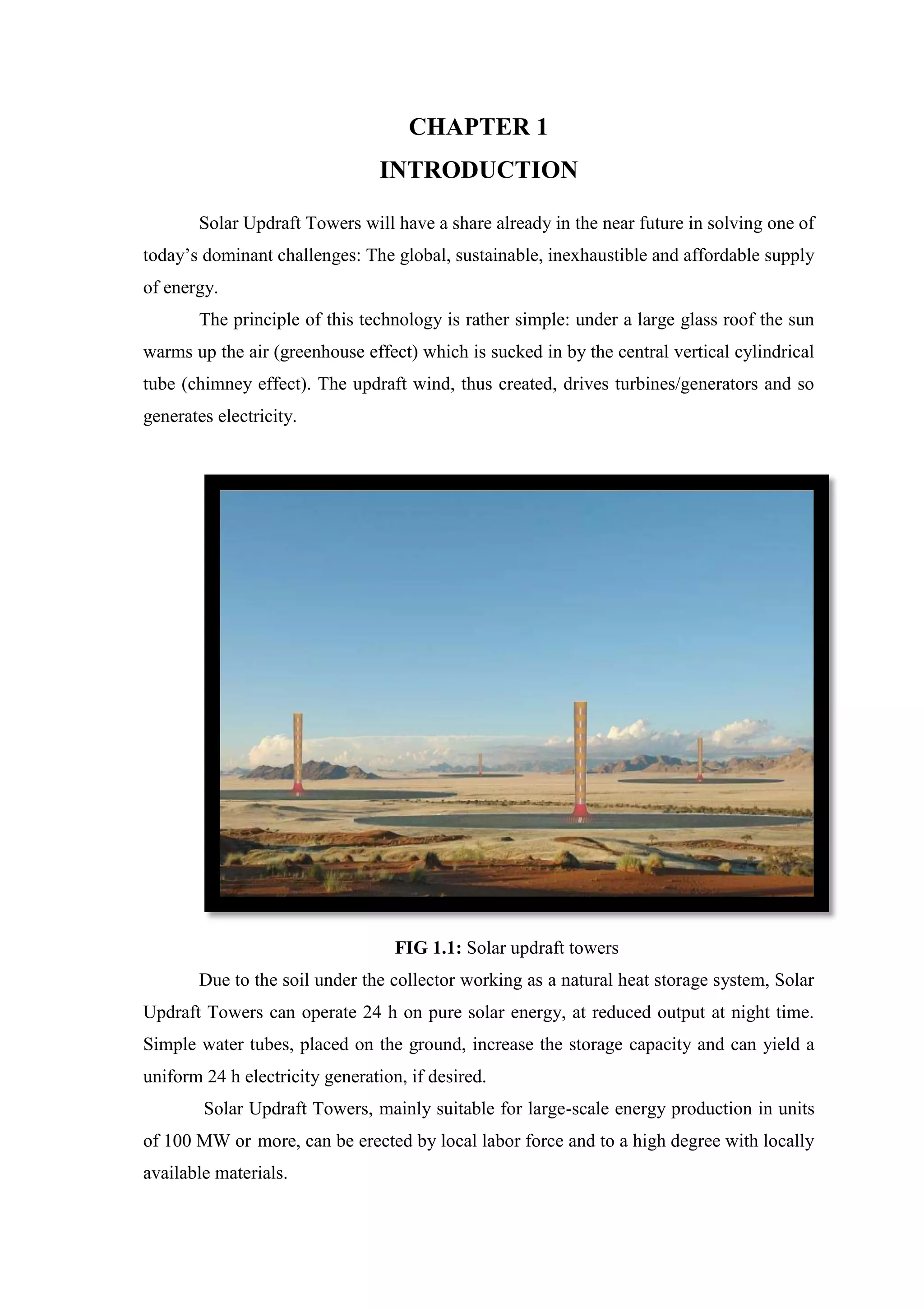
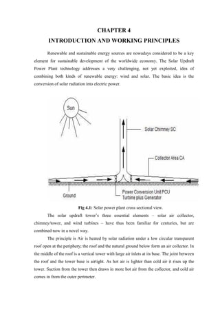
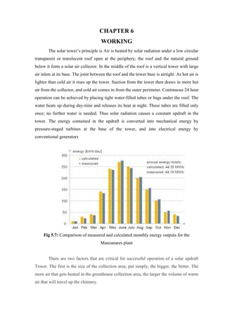
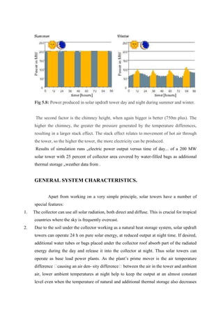
SlideShare a Scribd company logo
CHAPTER 1
INTRODUCTION
Solar Updraft Towers will have a share already in the near future in solving one of
today’s dominant challenges: The global, sustainable, inexhaustible and affordable supply
of energy.
The principle of this technology is rather simple: under a large glass roof the sun
warms up the air (greenhouse effect) which is sucked in by the central vertical cylindrical
tube (chimney effect). The updraft wind, thus created, drives turbines/generators and so
generates electricity.
FIG 1.1: Solar updraft towers
Due to the soil under the collector working as a natural heat storage system, Solar
Updraft Towers can operate 24 h on pure solar energy, at reduced output at night time.
Simple water tubes, placed on the ground, increase the storage capacity and can yield a
uniform 24 h electricity generation, if desired.
Solar Updraft Towers, mainly suitable for large-scale energy production in units
of 100 MW or more, can be erected by local labor force and to a high degree with locally
available materials.
Solar Updraft Towers can be built in desert countries either to cover regional
demand resp. to save oil reserves, or to contribute to the energy supply of e.g. Europe,
since the electricity produced by Solar Updraft Towers in the sunny countries can be
transported and sold to any place either by transmission lines or – as liquid hydrogen – by
ships without substantial losses.
Solar Updraft Towers are particularly reliable. Turbines and generators are the
plant’s only moving parts. This simple and robust structure guarantees operation that
needs little maintenance and of course no combustible fuel.
CHAPTER 2
PROBLEM DESCRIPTION
Current electricity production from coal, oil and natural gas is damaging the
environment, is non- sustainable and many developing countries cannot afford these
energy sources. Nuclear power stations are an unacceptable risk in most locations. But
inadequate energy supply leads to or maintains poverty, which commonly is accompanied
by population explosion: a vicious circle.
Sensible technology for the wide use of renewable energy must be simple and
reliable, accessible to the technologically less developed countries that are sunny and
often have limited raw material resources, it should not need cooling water or produce
waste and should be based on environmentally sound production from renewable or
recyclable materials
Fig 2.1: Distribution of yearly solar irradiation.
Unlike conventional oil / gas fired and also other solar-thermal power plants,
Solar Updraft Towers do not need cooling water. This is a key advantage in many sunny
countries that already have major problems with water supply.
Electricity from Solar Updraft Towers is the cheapest when compared with other
solar power plants. Nevertheless its energy production costs are still somewhat higher
than those of “conventional” coal or gas-fired power plants. However, the approaching
shortfall of fuel reserves in combination with dramatically increasing demand will soon
balance the cost difference of today and later even reverse it. We expect this “break-even-
point” already at a value of 60 to 80 $/barrel of crude oil. Therefore it is time now to
build large-scale solar power plants and also large-scale Solar Updraft Towers.
CHAPTER 3
LITERATURE REVIEW
Detailed theoretical preliminary research and a wide range of wind tunnel
experiments led to the establishment of an experimental plant with a peak output of 50
kW on a site made available by the Spanish utility Union Electrica Fenosa in Manzanares
about 150 km south of Madrid in 1981 funds provided by the German Ministry of
Research and Technology.
The aim of this research project was to verify, through field measurements, the
performance projected from calculations based on theory, and to examine the influence of
individual components on the plant’s output and efficiency under realistic engineering
and meteorological conditions.
The tower comprises a guyed tube of trapezoidal sheets, gauge 1.25 mm, and
corrugation depth 150 mm. The tube stands on a sup- porting ring 10 m above ground
level; this ring is carried by 8 thin tubular columns, so that the warm air can flow in
practically un- hindered at the base of the tower. A prestressed membrane of plastic-
coated fabric, shaped to provide good flow characteristics, forms the transition between
the roof and the tower.
The plastic membranes are clamped to a frame and stressed down to the ground at
the center by use of a plate with drain holes. The initial investment cost of plastic
membranes is lower than that of glass; however, in Manzanares the membranes got brittle
with time and thus tended to tear. Material temperature and UV stability and design
improvements e.g., membrane domes achieved in the last years may help to overcome
this particular disadvantage.
In order to arrive at a thorough understanding of the physical relationships and to
evolve and identify points of approach for possible improvements, a computer simulation
code was developed that describes the individual components, their performance, and
their dynamic interaction. This program was verified on the basis of experimental
measurement results from Manzanares. To- day, it is a development tool that takes all
known effects into account, and with the aid of which the thermodynamic behavior of
large-scale plants under given meteorological conditions can be calculated in advance
From mid-1986 to early 1989 the plant was run on a regular daily basis. As soon
as the air velocity in the tower exceeded a set value, typically 2.5 m/s, the plant started up
automatically and was automatically connected to the public grid. During this 32 month
period, the plant ran, fully automatically, an average of 8.9 h per day.
Measured and calculated average monthly energy outputs, showing that there is
good agreement between the theoretical and measured values. Overall, it may be said that
the optical and thermodynamic processes in a solar tower are well understood and that
models have attained a degree of maturity that accurately reproduces plant behavior
under given meteorological conditions.
CHAPTER 4
INTRODUCTION AND WORKING PRINCIPLES
Renewable and sustainable energy sources are nowadays considered to be a key
element for sustainable development of the worldwide economy. The Solar Updraft
Power Plant technology addresses a very challenging, not yet exploited, idea of
combining both kinds of renewable energy: wind and solar. The basic idea is the
conversion of solar radiation into electric power.
Fig 4.1: Solar power plant cross sectional view.
The solar updraft tower’s three essential elements – solar air collector,
chimney/tower, and wind turbines – have thus been familiar for centuries, but are
combined now in a novel way.
The principle is Air is heated by solar radiation under a low circular transparent
roof open at the periphery; the roof and the natural ground below form an air collector. In
the middle of the roof is a vertical tower with large air inlets at its base. The joint between
the roof and the tower base is airtight. As hot air is lighter than cold air it rises up the
tower. Suction from the tower then draws in more hot air from the collector, and cold air
comes in from the outer perimeter.
Thus solar radiation causes a constant updraft in the tower. The energy contained
in the updraft is converted into mechanical energy by pressure-staged turbines at the base
of the tower, and into electrical energy by conventional generators.
Electrical output of a solar updraft tower is proportional to the volume included
within the tower height and collector area The same output may result from a larger tower
with a smaller collector area and vice versa.
Continuous 24 hours-operation can be achieved by placing tight water-filled tubes
or bags under the roof. The water heats up during day-time and releases its heat at night.
These tubes are filled only once, no further water is needed.
CHAPTER 5
COMPONENTS
5.1 COLLECTOR
Hot air for the solar updraft tower is produced by the greenhouse effect in a
simple air collector consisting of a glass or plastic film glazing stretched nearly
horizontally several meters above the ground. The height of the glazing increases towards
the tower base, finally the air is diverted from horizontal into vertical movement with
minimum friction loss. This glazing admits the shortwave solar radiation to penetrate and
retains long wave re-radiation from the heated ground. Thus the ground under the roof
heats up and transfers its heat to the air above flowing radially from the outside to the
tower.
Fig 5.1: Glass roof of the prototype plant at Manzanares, Spain
5.2 STORAGE
If additional thermal storage capacity is desired, water filled black tubes or bags
are laid down side by side on the radiation absorbing soil under the collector.
Fig 5.2: Principle of thermal energy storage with water-filled tubes
Fig 5.3: Effect of heat storage underneath the collector roof using water-filled black
tubes.
The tubes are filled with water once and remain closed thereafter, so that no
evaporation can take place. The volume of water in the tubes is selected to correspond to
a water layer with a depth of 5 to 20 cm depending on the desired power output
characteristics
5.3 TOWER
The tower itself is the plant's actual thermal engine. It is a pressure tube with low
friction loss (like a hydro power station pressure tube or pen stock) because of its
favorable surface-volume ratio. The updraft of the air heated in the collector is
approximately proportional to the air temperature rise in the collector and to the height of
the tower. In a large solar updraft tower the collector raises the air temperature by about
30 to 35 K. This produces an updraft velocity in the tower of about 15m/s at full load. It
is thus possible to enter into an operating solar tower power plant for maintenance
without danger from high air velocities.
Fig 5.4: Prototype of the solar tower prototype plant at Manza nares, Spain
5.4 TURBINES
Using turbines, mechanical output in the form of rotational energy can be derived
from the air current in the tower. Turbines in a solar updraft tower do not work with
staged velocity like a free- running wind energy converter, but as a shrouded pressure-
staged wind turbo generator, in which, similarly to a hydroelectric power station, static
pressure is converted to rotational energy using a cased turbine. The specific power
output (power per area swept by the rotor) of a shrouded pressure- staged turbine in the
solar updraft tower is roughly one order of magnitude higher than that of a velocity
staged wind turbine. Air speed before and after the turbine is about the same. The output
achieved is proportional to the product of volume flow per time unit and the pressure
differential over the turbine. With a view to maximum energy yield the aim of the turbine
control system is to maximize this product under all operating conditions.
Fig 5.5: Turbines of solar updraft power plant.
To this end, blade pitch is adjusted during operation to regulate power output
according to the altering airspeed and airflow. If the flat sides of the blades are
perpendicular to the airflow, the turbine does not turn. If the blades are parallel to the air
flow and allow the air to flow through undisturbed there is no drop in pressure at the
turbine and no electricity is generated. Between these two extremes there is an optimum
blade setting: the output is maximized if the pressure drop at the turbine is about 80 % of
the total pressure differential available, depending on weather and operating conditions as
well as on plant design.
CHAPTER 6
WORKING
The solar tower’s principle is Air is heated by solar radiation under a low circular
transparent or translucent roof open at the periphery; the roof and the natural ground
below it form a solar air collector. In the middle of the roof is a vertical tower with large
air inlets at its base. The joint between the roof and the tower base is airtight. As hot air is
lighter than cold air it rises up the tower. Suction from the tower then draws in more hot
air from the collector, and cold air comes in from the outer perimeter. Continuous 24 hour
operation can be achieved by placing tight water-filled tubes or bags under the roof. The
water heats up during day-time and releases its heat at night. These tubes are filled only
once; no further water is needed. Thus solar radiation causes a constant updraft in the
tower. The energy contained in the updraft is converted into mechanical energy by
pressure-staged turbines at the base of the tower, and into electrical energy by
conventional generators
Fig 5.7: Comparison of measured and calculated monthly energy outputs for the
Manzanares plant
There are two factors that are critical for successful operation of a solar updraft
Tower. The first is the size of the collection area; put simply, the bigger, the better. The
more air that gets heated in the greenhouse collection area, the larger the volume of warm
air that will travel up the chimney.
Fig 5.8: Power produced in solar updraft tower day and night during summer and winter.
The second factor is the chimney height, when again bigger is better (750m plus). The
higher the chimney, the greater the pressure generated by the temperature differences,
resulting in a larger stack effect. The stack effect relates to movement of hot air through
the tower, so the higher the tower, the more electricity can be produced.
Results of simulation runs „electric power output versus time of day... of a 200 MW
solar tower with 25 percent of collector area covered by water-filled bags as additional
thermal storage „weather data from .
GENERAL SYSTEM CHARACTERISTICS.
Apart from working on a very simple principle, solar towers have a number of
special features:
1. The collector can use all solar radiation, both direct and diffuse. This is crucial for tropical
countries where the sky is frequently overcast.
2. Due to the soil under the collector working as a natural heat storage system, solar updraft
towers can operate 24 h on pure solar energy, at reduced output at night time. If desired,
additional water tubes or bags placed under the collector roof absorb part of the radiated
energy during the day and release it into the collector at night. Thus solar towers can
operate as base load power plants. As the plant’s prime mover is the air temperature
difference �causing an air den- sity difference� between the air in the tower and ambient
air, lower ambient temperatures at night help to keep the output at an almost constant
level even when the temperature of natural and additional thermal storage also decreases
without sunshine, as the temperature difference remains practically the same.
3. Solar towers are particularly reliable and not liable to break down, in comparison with
other power plants. Turbines and generators—subject to a steady flow of air—are the
plant’s only moving parts. This simple and robust structure guarantees operation that
needs little maintenance and of course no combustible fuel.
4. Unlike conventional power stations and also some other solar-thermal power station
types, solar towers do not need cooling water. This is a key advantage in the many sunny
countries that already have major problems with water supply.
5. The building materials needed for solar towers, mainly concrete and glass, are available
everywhere in sufficient quantities. In fact, with the energy taken from the solar tower
itself and the stone and sand available in the desert, they can be reproduced on site.
Energy payback time is two to three years. 

6. Solar towers can be built now, even in less industrially developed countries. The industry
already available in most countries is entirely adequate for solar tower requirements. No
investment in high-tech manufacturing plants is needed.
7. Even in poor countries it is possible to build a large plant without high foreign currency
expenditure by using local resources and work-force; this creates large numbers of jobs
while significantly reducing the required capital investment and thus the cost of
generating electricity.
Nevertheless, solar towers also have features that make them less suitable for some sites:
A. They require large areas of flat land. This land should be available at low cost, which
means that there should be no competing usage, like, e.g., intensive agriculture, for the
land.
B. Solar towers are not adequate for earthquake prone areas, as in this case tower costs
would increase drastically.
C. Zones with frequent sand storms should also be avoided, as either collector
performance losses or collector operation and maintenance costs would be substantial
there.
CHAPTER 7
ECONOMY
Based on specific costs, dimensions and electricity output from Table 2,
investment costs were calculated. With the respective annual energy outputs from
simulation runs, levelized electricity costs are calculated using an interest rate of 6
percent and a depreciation time of 30 years.
Fig 7.1: Electricity Cost for Oil-Fired Power Plants and Solar Updraft Towers
From Table 3 it becomes obvious that LEC for a small 5 MW solar tower are
relatively high, comparable, e.g., to a PV-System. With increasing plant size, a significant
reduction of electricity generation cost is associated, leading to LEC of 0.07 �C/kWh for
a 200 MW plant in the given example at an interest rate of 6 percent.
General comparison between power generation using a coal-fired plant and a solar
tower is shown. In the selected example, electricity costs for the solar tower are higher
than those for the coal-fired power plant in the first years of operation.
In countries with very low wages, investment costs, and there- fore mostly
electricity generation costs of the solar tower, will be further reduced. This holds
especially true as the collector, which alone amounts to roughly one half of the overall
solar tower in- vestment costs, is a low-tech component and can be built any- where with
unskilled labor.
CHAPTER 8
CONCLUSIONS
Solar updraft towers certainly have the potential to become a useful tool to help
combat climate change. If production costs can be reduced, these would be ideal in third
world countries where there is lots of cheap space to build the plants.
The updraft solar tower works on a simple proven principle; its physics are well
understood. As thermodynamic efficiency of the plant increases with tower height, such
plants have to be large to become cost competitive. Large plants mean high investment
costs, which are mostly due to labor costs. This in return creates jobs, and a high net
domestic product for the country with increased tax income and reduced social costs
human dignity, social harmony, and in addition no costly consumption of fossil fuels. The
latter reduces dependence on imported oil and coal, which is especially beneficial for the
developing countries, releasing means for their development.
There is no ecological harm and no consumption of resources, not even for the
construction, as solar towers predominantly consist of concrete and glass which are made
from sand and stone plus self-generated energy. Consequently in desert areas with
inexhaustible sand and stone—solar towers can reproduce them- selves. A truly
sustainable source of energy!
There are also patented designs that replace the large concrete chimney with a low
cost fabric designs held in position using successive tubular balloons filled with lighter
than air gas (such as helium). These would make the plants far cheaper to produce,
although these have not been tested on a commercial scale.
REFERENCES
1. Anel Menges,1995, The solar chimney: electricity from sun.
2. EACWE 5 Florence, Italy 19th – 23rd July 2009 “ The Solar Updraft Power Plant:
Design and Optimization of the Tower for Wind Effects” Journal of Solar Energy
Engineering
3. Schlaich, J., 1995, The Solar Chimney, Edition Axel Menges, Stuttgart, Germany.
4. Gannon, A. J., and Backstro ̈m, T. W. v., 2000, ‘‘Solar Chimney Cycle Analysis
With System Loss and Solar Collector Performance,’’ J. Sol. Energy Eng., pp.
133 – 137.
5. Weinrebe, G., 1999, ‘‘Greenhouse Gas Mitigation With Solar Thermal Power
Plants,’’ Proceedings of the PowerGen Europe 1999 Conference, Frankfurt,
Germany, 1 – 3 June.

More Related Content

What's hot

Solar Energy Seminar
Solar Energy SeminarSolar Energy Seminar
Solar Energy Seminar
Abdulaziz Mohammed Baras
 
Solar pv -simulation and designing
Solar pv -simulation and designingSolar pv -simulation and designing
Solar pv -simulation and designing
TusharKumarSingh4
 
Solar photovoltaic systems
Solar photovoltaic systemsSolar photovoltaic systems
Solar photovoltaic systems
anish_hercules
 
Floating Solar PV - An Introduction
Floating Solar PV -  An Introduction Floating Solar PV -  An Introduction
Floating Solar PV - An Introduction
Gensol Engineering Limited
 
Nano tree ppt
Nano tree pptNano tree ppt
Nano tree ppt
chakri218
 
Solar power.ppt
Solar power.pptSolar power.ppt
Solar power.ppt
Fauzia Samreen
 
Solar wind hybrid power system ppt
Solar wind hybrid power system pptSolar wind hybrid power system ppt
Solar wind hybrid power system ppt
Vihar Modi
 
Solar PV Cells, Module and Array
Solar PV Cells, Module and ArraySolar PV Cells, Module and Array
Solar PV Cells, Module and Array
Dr Naim R Kidwai
 
Understanding Solar Energy
Understanding Solar EnergyUnderstanding Solar Energy
Understanding Solar Energy
Centre for Application of renewable Energy
 
Solar Energy
Solar EnergySolar Energy
Solar Energy
danyalanjum
 
Solar photovoltaic powerpoint
Solar photovoltaic powerpointSolar photovoltaic powerpoint
Solar photovoltaic powerpoint
William Wallace
 
Rooftop PV System Shubham Gaurav
Rooftop PV System Shubham GauravRooftop PV System Shubham Gaurav
Rooftop PV System Shubham Gaurav
Shubham Gaurav
 
SOLAR ENERGY TECHNOLOGY
SOLAR ENERGY TECHNOLOGYSOLAR ENERGY TECHNOLOGY
SOLAR ENERGY TECHNOLOGY
Vanita Thakkar
 
Ppt on design of solar photovoltaic generation for residential building
Ppt on design of solar photovoltaic generation for residential buildingPpt on design of solar photovoltaic generation for residential building
Ppt on design of solar photovoltaic generation for residential buildingSiya Agarwal
 
Solar energy ppt
Solar energy pptSolar energy ppt
Solar energy ppt
Shantanu Kumar
 
Solar pv systems
Solar pv systemsSolar pv systems
Solar pv systems
Stephen Jones
 
Solar power project
Solar power projectSolar power project
Solar power project
shazaan98
 
Rural electrification through solar and wind hybrid system
Rural electrification through solar and wind hybrid systemRural electrification through solar and wind hybrid system
Rural electrification through solar and wind hybrid system
nissy marla
 
Economics of Solar PV Power
Economics of Solar PV PowerEconomics of Solar PV Power
Economics of Solar PV PowerSudhanwa Sahoo
 

What's hot (20)

Solar Energy Seminar
Solar Energy SeminarSolar Energy Seminar
Solar Energy Seminar
 
Solar pv -simulation and designing
Solar pv -simulation and designingSolar pv -simulation and designing
Solar pv -simulation and designing
 
Solar photovoltaic systems
Solar photovoltaic systemsSolar photovoltaic systems
Solar photovoltaic systems
 
Floating Solar PV - An Introduction
Floating Solar PV -  An Introduction Floating Solar PV -  An Introduction
Floating Solar PV - An Introduction
 
Nano tree ppt
Nano tree pptNano tree ppt
Nano tree ppt
 
Solar power.ppt
Solar power.pptSolar power.ppt
Solar power.ppt
 
Solar wind hybrid power system ppt
Solar wind hybrid power system pptSolar wind hybrid power system ppt
Solar wind hybrid power system ppt
 
Solar PV Cells, Module and Array
Solar PV Cells, Module and ArraySolar PV Cells, Module and Array
Solar PV Cells, Module and Array
 
Solar rooftop presentation
Solar rooftop presentationSolar rooftop presentation
Solar rooftop presentation
 
Understanding Solar Energy
Understanding Solar EnergyUnderstanding Solar Energy
Understanding Solar Energy
 
Solar Energy
Solar EnergySolar Energy
Solar Energy
 
Solar photovoltaic powerpoint
Solar photovoltaic powerpointSolar photovoltaic powerpoint
Solar photovoltaic powerpoint
 
Rooftop PV System Shubham Gaurav
Rooftop PV System Shubham GauravRooftop PV System Shubham Gaurav
Rooftop PV System Shubham Gaurav
 
SOLAR ENERGY TECHNOLOGY
SOLAR ENERGY TECHNOLOGYSOLAR ENERGY TECHNOLOGY
SOLAR ENERGY TECHNOLOGY
 
Ppt on design of solar photovoltaic generation for residential building
Ppt on design of solar photovoltaic generation for residential buildingPpt on design of solar photovoltaic generation for residential building
Ppt on design of solar photovoltaic generation for residential building
 
Solar energy ppt
Solar energy pptSolar energy ppt
Solar energy ppt
 
Solar pv systems
Solar pv systemsSolar pv systems
Solar pv systems
 
Solar power project
Solar power projectSolar power project
Solar power project
 
Rural electrification through solar and wind hybrid system
Rural electrification through solar and wind hybrid systemRural electrification through solar and wind hybrid system
Rural electrification through solar and wind hybrid system
 
Economics of Solar PV Power
Economics of Solar PV PowerEconomics of Solar PV Power
Economics of Solar PV Power
 

Viewers also liked

SOLAR UPGRADE TOWER
SOLAR UPGRADE TOWERSOLAR UPGRADE TOWER
SOLAR UPGRADE TOWER
MD NAWAZ
 
csp (concentrated solar power) technology
csp (concentrated solar power) technologycsp (concentrated solar power) technology
csp (concentrated solar power) technology
Arvind Dautaniya
 
seminar report on solar power tower
seminar report on solar power towerseminar report on solar power tower
seminar report on solar power tower
कौशिक किशोर
 
Solar Tower
Solar TowerSolar Tower
Solar Towerhjayan
 
Solar Power Tower
Solar Power TowerSolar Power Tower
Solar Power Tower
Arpan_07
 
Concentrated Solar Power Technologies (CSP)
Concentrated Solar Power Technologies (CSP)Concentrated Solar Power Technologies (CSP)
Concentrated Solar Power Technologies (CSP)
swapnil_energy
 
Solar tower
Solar towerSolar tower
Solar tower
Aziz Companiwala
 
Israel building world’s tallest solar tower
Israel building world’s tallest solar towerIsrael building world’s tallest solar tower
Israel building world’s tallest solar tower
BizLed
 
Solar Thermal Power
Solar Thermal PowerSolar Thermal Power
Solar Thermal Power
Seminar Links
 
guaglobal.com
guaglobal.comguaglobal.com
guaglobal.com
GUA Global
 
Solar City Tower
Solar City TowerSolar City Tower
Solar City Tower
TheWatchable Web
 
A project report on hybrid chimney
A project report on hybrid chimneyA project report on hybrid chimney
A project report on hybrid chimney
MohitIIM
 
Wind Turbine Generator (WTG) Yawing And Furling Mechanisms
Wind Turbine Generator (WTG) Yawing And Furling MechanismsWind Turbine Generator (WTG) Yawing And Furling Mechanisms
Wind Turbine Generator (WTG) Yawing And Furling Mechanisms
mareenotmarie
 
The Solar Chimney
The Solar ChimneyThe Solar Chimney
The Solar Chimney
javadkhezri
 
Aman ppt
Aman  pptAman  ppt
Aman ppt
aman anand
 
Vertical Wind Turbine Generator Presentation
Vertical Wind Turbine Generator PresentationVertical Wind Turbine Generator Presentation
Vertical Wind Turbine Generator PresentationPeter Okwudi
 
Implementation of renewable energy resources in india-solar updraft tower
Implementation of renewable energy resources in india-solar updraft towerImplementation of renewable energy resources in india-solar updraft tower
Implementation of renewable energy resources in india-solar updraft towerNeha Chouhan
 
Solar Power Science and Projects
Solar Power Science and ProjectsSolar Power Science and Projects
Solar Power Science and Projects
Rajasthan Techanical University, Kota
 
Seminar airborne wind turbines
Seminar   airborne wind turbinesSeminar   airborne wind turbines
Seminar airborne wind turbines
Parag Deshpande
 
Rio solar tower
Rio solar towerRio solar tower
Rio solar tower
PoweredTemplate.com
 

Viewers also liked (20)

SOLAR UPGRADE TOWER
SOLAR UPGRADE TOWERSOLAR UPGRADE TOWER
SOLAR UPGRADE TOWER
 
csp (concentrated solar power) technology
csp (concentrated solar power) technologycsp (concentrated solar power) technology
csp (concentrated solar power) technology
 
seminar report on solar power tower
seminar report on solar power towerseminar report on solar power tower
seminar report on solar power tower
 
Solar Tower
Solar TowerSolar Tower
Solar Tower
 
Solar Power Tower
Solar Power TowerSolar Power Tower
Solar Power Tower
 
Concentrated Solar Power Technologies (CSP)
Concentrated Solar Power Technologies (CSP)Concentrated Solar Power Technologies (CSP)
Concentrated Solar Power Technologies (CSP)
 
Solar tower
Solar towerSolar tower
Solar tower
 
Israel building world’s tallest solar tower
Israel building world’s tallest solar towerIsrael building world’s tallest solar tower
Israel building world’s tallest solar tower
 
Solar Thermal Power
Solar Thermal PowerSolar Thermal Power
Solar Thermal Power
 
guaglobal.com
guaglobal.comguaglobal.com
guaglobal.com
 
Solar City Tower
Solar City TowerSolar City Tower
Solar City Tower
 
A project report on hybrid chimney
A project report on hybrid chimneyA project report on hybrid chimney
A project report on hybrid chimney
 
Wind Turbine Generator (WTG) Yawing And Furling Mechanisms
Wind Turbine Generator (WTG) Yawing And Furling MechanismsWind Turbine Generator (WTG) Yawing And Furling Mechanisms
Wind Turbine Generator (WTG) Yawing And Furling Mechanisms
 
The Solar Chimney
The Solar ChimneyThe Solar Chimney
The Solar Chimney
 
Aman ppt
Aman  pptAman  ppt
Aman ppt
 
Vertical Wind Turbine Generator Presentation
Vertical Wind Turbine Generator PresentationVertical Wind Turbine Generator Presentation
Vertical Wind Turbine Generator Presentation
 
Implementation of renewable energy resources in india-solar updraft tower
Implementation of renewable energy resources in india-solar updraft towerImplementation of renewable energy resources in india-solar updraft tower
Implementation of renewable energy resources in india-solar updraft tower
 
Solar Power Science and Projects
Solar Power Science and ProjectsSolar Power Science and Projects
Solar Power Science and Projects
 
Seminar airborne wind turbines
Seminar   airborne wind turbinesSeminar   airborne wind turbines
Seminar airborne wind turbines
 
Rio solar tower
Rio solar towerRio solar tower
Rio solar tower
 

Similar to SOLAR UPDRAFT POWER PLANT

Solar Chimney
Solar ChimneySolar Chimney
Solar Chimney
Ahmed Amin
 
Solar Chimney Power Plant-A Review
Solar Chimney Power Plant-A ReviewSolar Chimney Power Plant-A Review
Solar Chimney Power Plant-A Review
IJMER
 
Thermal Storage Comparison for Variable Basement Kinds of a Solar Chimney Pro...
Thermal Storage Comparison for Variable Basement Kinds of a Solar Chimney Pro...Thermal Storage Comparison for Variable Basement Kinds of a Solar Chimney Pro...
Thermal Storage Comparison for Variable Basement Kinds of a Solar Chimney Pro...
Waqas Tariq
 
ACOUSTICS AND ENERGY
ACOUSTICS AND ENERGYACOUSTICS AND ENERGY
ACOUSTICS AND ENERGY
Shristi Kuikel
 
Pawan report
Pawan reportPawan report
Pawan report
Pawan Pandit
 
Redesign and Fabrication of Solar Power Tower using CAD and FEM Analysis
Redesign and Fabrication of Solar Power Tower using CAD and  FEM AnalysisRedesign and Fabrication of Solar Power Tower using CAD and  FEM Analysis
Redesign and Fabrication of Solar Power Tower using CAD and FEM Analysis
IJMER
 
International Journal of Computational Engineering Research(IJCER)
 International Journal of Computational Engineering Research(IJCER)  International Journal of Computational Engineering Research(IJCER)
International Journal of Computational Engineering Research(IJCER)
ijceronline
 
SolarThermal.pptx
SolarThermal.pptxSolarThermal.pptx
SolarThermal.pptx
RajaDesingu2
 
SolarThermal.pdf
SolarThermal.pdfSolarThermal.pdf
SolarThermal.pdf
anaveenkumar4
 
SOLAR AC
SOLAR ACSOLAR AC
Green Studio Handbook - Part 4
Green Studio Handbook - Part 4Green Studio Handbook - Part 4
Green Studio Handbook - Part 4Galala University
 
Renewa ble energy
Renewa ble energyRenewa ble energy
Renewa ble energy
Rohit Satyam
 
Solar Chimney Power Plant-A Review
Solar Chimney Power Plant-A ReviewSolar Chimney Power Plant-A Review
Solar Chimney Power Plant-A Review
IJMER
 
Planting The Ceed
Planting The CeedPlanting The Ceed
Planting The Ceedmosgraphics
 
Enhancing Photoelectric Conversion Efficiency of Solar Panel by Water Cooling
Enhancing Photoelectric Conversion Efficiency of Solar Panel by Water CoolingEnhancing Photoelectric Conversion Efficiency of Solar Panel by Water Cooling
Enhancing Photoelectric Conversion Efficiency of Solar Panel by Water Cooling
IJAPEJOURNAL
 
Solar energy power plants and its efficiency enhancement
Solar energy power plants and its efficiency enhancementSolar energy power plants and its efficiency enhancement
Solar energy power plants and its efficiency enhancement
Govind Kumar Mishra
 
concentrated solar powerplant
concentrated solar powerplant concentrated solar powerplant
concentrated solar powerplant
Rasmin Sahoo
 

Similar to SOLAR UPDRAFT POWER PLANT (20)

Solar Chimney
Solar ChimneySolar Chimney
Solar Chimney
 
Solar Chimney Power Plant-A Review
Solar Chimney Power Plant-A ReviewSolar Chimney Power Plant-A Review
Solar Chimney Power Plant-A Review
 
Thermal Storage Comparison for Variable Basement Kinds of a Solar Chimney Pro...
Thermal Storage Comparison for Variable Basement Kinds of a Solar Chimney Pro...Thermal Storage Comparison for Variable Basement Kinds of a Solar Chimney Pro...
Thermal Storage Comparison for Variable Basement Kinds of a Solar Chimney Pro...
 
ACOUSTICS AND ENERGY
ACOUSTICS AND ENERGYACOUSTICS AND ENERGY
ACOUSTICS AND ENERGY
 
Pawan report
Pawan reportPawan report
Pawan report
 
Redesign and Fabrication of Solar Power Tower using CAD and FEM Analysis
Redesign and Fabrication of Solar Power Tower using CAD and  FEM AnalysisRedesign and Fabrication of Solar Power Tower using CAD and  FEM Analysis
Redesign and Fabrication of Solar Power Tower using CAD and FEM Analysis
 
International Journal of Computational Engineering Research(IJCER)
 International Journal of Computational Engineering Research(IJCER)  International Journal of Computational Engineering Research(IJCER)
International Journal of Computational Engineering Research(IJCER)
 
SolarThermal.pptx
SolarThermal.pptxSolarThermal.pptx
SolarThermal.pptx
 
SolarThermal.pdf
SolarThermal.pdfSolarThermal.pdf
SolarThermal.pdf
 
SOLAR AC
SOLAR ACSOLAR AC
SOLAR AC
 
Green Studio Handbook - Part 4
Green Studio Handbook - Part 4Green Studio Handbook - Part 4
Green Studio Handbook - Part 4
 
Renewa ble energy
Renewa ble energyRenewa ble energy
Renewa ble energy
 
Solar Chimney Power Plant-A Review
Solar Chimney Power Plant-A ReviewSolar Chimney Power Plant-A Review
Solar Chimney Power Plant-A Review
 
Planting The Ceed
Planting The CeedPlanting The Ceed
Planting The Ceed
 
Enhancing Photoelectric Conversion Efficiency of Solar Panel by Water Cooling
Enhancing Photoelectric Conversion Efficiency of Solar Panel by Water CoolingEnhancing Photoelectric Conversion Efficiency of Solar Panel by Water Cooling
Enhancing Photoelectric Conversion Efficiency of Solar Panel by Water Cooling
 
Thermal Energy
Thermal EnergyThermal Energy
Thermal Energy
 
Solar energy power plants and its efficiency enhancement
Solar energy power plants and its efficiency enhancementSolar energy power plants and its efficiency enhancement
Solar energy power plants and its efficiency enhancement
 
concentrated solar powerplant
concentrated solar powerplant concentrated solar powerplant
concentrated solar powerplant
 
140120119168 2181910
140120119168 2181910140120119168 2181910
140120119168 2181910
 
Pearl river tower,
Pearl river tower,Pearl river tower,
Pearl river tower,
 

More from Denny John

ADDITIVE MANUFACTURING
ADDITIVE MANUFACTURINGADDITIVE MANUFACTURING
ADDITIVE MANUFACTURING
Denny John
 
ALL Non destructive testings at one pdf
ALL Non destructive testings at one pdfALL Non destructive testings at one pdf
ALL Non destructive testings at one pdf
Denny John
 
REFRIGERATION SYSTEM
REFRIGERATION SYSTEMREFRIGERATION SYSTEM
REFRIGERATION SYSTEM
Denny John
 
CAPP , JIT, FMS
CAPP , JIT, FMSCAPP , JIT, FMS
CAPP , JIT, FMS
Denny John
 
geometric modelling and PLC
geometric modelling and PLCgeometric modelling and PLC
geometric modelling and PLC
Denny John
 
NC part programing & Robotics
NC part programing & RoboticsNC part programing & Robotics
NC part programing & Robotics
Denny John
 
evolution of cad/cam
evolution of cad/camevolution of cad/cam
evolution of cad/cam
Denny John
 
NON TRADITIONAL MACHINING & MATERIAL ADDITION PROCESS ( as per MGU syllabus)
NON TRADITIONAL MACHINING & MATERIAL ADDITION PROCESS ( as per MGU syllabus)NON TRADITIONAL MACHINING & MATERIAL ADDITION PROCESS ( as per MGU syllabus)
NON TRADITIONAL MACHINING & MATERIAL ADDITION PROCESS ( as per MGU syllabus)
Denny John
 
COMPOSITES ( as per MGU syllabus)
COMPOSITES ( as per MGU syllabus)COMPOSITES ( as per MGU syllabus)
COMPOSITES ( as per MGU syllabus)
Denny John
 
CERAMICS ( as per MGU syllabus)
CERAMICS ( as per MGU syllabus)CERAMICS ( as per MGU syllabus)
CERAMICS ( as per MGU syllabus)
Denny John
 
Machining and Thermal aspects (MGU S8 ME)
Machining and Thermal aspects (MGU S8 ME)Machining and Thermal aspects (MGU S8 ME)
Machining and Thermal aspects (MGU S8 ME)
Denny John
 
Theory of metal cutting MG University(S8 Production Notes)
Theory of metal cutting MG University(S8 Production Notes)Theory of metal cutting MG University(S8 Production Notes)
Theory of metal cutting MG University(S8 Production Notes)
Denny John
 
powder metallurgy and micromachining notes
powder metallurgy and micromachining notespowder metallurgy and micromachining notes
powder metallurgy and micromachining notes
Denny John
 
DESIGN AND FABRICATION OF DISC TYPE HYBRID TURBINE-PUMP
DESIGN AND FABRICATION OF DISC TYPE HYBRID TURBINE-PUMPDESIGN AND FABRICATION OF DISC TYPE HYBRID TURBINE-PUMP
DESIGN AND FABRICATION OF DISC TYPE HYBRID TURBINE-PUMP
Denny John
 
SIMULATION AND OPTIMIZATION OF MATERIAL FLOW FORGING DEFECTS IN AUTOMOBILE CO...
SIMULATION AND OPTIMIZATION OF MATERIAL FLOW FORGING DEFECTS IN AUTOMOBILE CO...SIMULATION AND OPTIMIZATION OF MATERIAL FLOW FORGING DEFECTS IN AUTOMOBILE CO...
SIMULATION AND OPTIMIZATION OF MATERIAL FLOW FORGING DEFECTS IN AUTOMOBILE CO...
Denny John
 
EXPERIMENTAL AND NUMERICAL STUDY OF A MICRO-COGENERATION STIRLING ENGINE FOR ...
EXPERIMENTAL AND NUMERICAL STUDY OF A MICRO-COGENERATION STIRLING ENGINE FOR ...EXPERIMENTAL AND NUMERICAL STUDY OF A MICRO-COGENERATION STIRLING ENGINE FOR ...
EXPERIMENTAL AND NUMERICAL STUDY OF A MICRO-COGENERATION STIRLING ENGINE FOR ...
Denny John
 
Optimisation of machining parameters for slot milling operation in Inconel 62...
Optimisation of machining parameters for slot milling operation in Inconel 62...Optimisation of machining parameters for slot milling operation in Inconel 62...
Optimisation of machining parameters for slot milling operation in Inconel 62...
Denny John
 
Challenges of future aircraft propulsion
Challenges of future aircraft propulsionChallenges of future aircraft propulsion
Challenges of future aircraft propulsion
Denny John
 
Design and testing of disc type hybrid turbine pump
Design and testing  of disc type hybrid turbine pumpDesign and testing  of disc type hybrid turbine pump
Design and testing of disc type hybrid turbine pump
Denny John
 

More from Denny John (19)

ADDITIVE MANUFACTURING
ADDITIVE MANUFACTURINGADDITIVE MANUFACTURING
ADDITIVE MANUFACTURING
 
ALL Non destructive testings at one pdf
ALL Non destructive testings at one pdfALL Non destructive testings at one pdf
ALL Non destructive testings at one pdf
 
REFRIGERATION SYSTEM
REFRIGERATION SYSTEMREFRIGERATION SYSTEM
REFRIGERATION SYSTEM
 
CAPP , JIT, FMS
CAPP , JIT, FMSCAPP , JIT, FMS
CAPP , JIT, FMS
 
geometric modelling and PLC
geometric modelling and PLCgeometric modelling and PLC
geometric modelling and PLC
 
NC part programing & Robotics
NC part programing & RoboticsNC part programing & Robotics
NC part programing & Robotics
 
evolution of cad/cam
evolution of cad/camevolution of cad/cam
evolution of cad/cam
 
NON TRADITIONAL MACHINING & MATERIAL ADDITION PROCESS ( as per MGU syllabus)
NON TRADITIONAL MACHINING & MATERIAL ADDITION PROCESS ( as per MGU syllabus)NON TRADITIONAL MACHINING & MATERIAL ADDITION PROCESS ( as per MGU syllabus)
NON TRADITIONAL MACHINING & MATERIAL ADDITION PROCESS ( as per MGU syllabus)
 
COMPOSITES ( as per MGU syllabus)
COMPOSITES ( as per MGU syllabus)COMPOSITES ( as per MGU syllabus)
COMPOSITES ( as per MGU syllabus)
 
CERAMICS ( as per MGU syllabus)
CERAMICS ( as per MGU syllabus)CERAMICS ( as per MGU syllabus)
CERAMICS ( as per MGU syllabus)
 
Machining and Thermal aspects (MGU S8 ME)
Machining and Thermal aspects (MGU S8 ME)Machining and Thermal aspects (MGU S8 ME)
Machining and Thermal aspects (MGU S8 ME)
 
Theory of metal cutting MG University(S8 Production Notes)
Theory of metal cutting MG University(S8 Production Notes)Theory of metal cutting MG University(S8 Production Notes)
Theory of metal cutting MG University(S8 Production Notes)
 
powder metallurgy and micromachining notes
powder metallurgy and micromachining notespowder metallurgy and micromachining notes
powder metallurgy and micromachining notes
 
DESIGN AND FABRICATION OF DISC TYPE HYBRID TURBINE-PUMP
DESIGN AND FABRICATION OF DISC TYPE HYBRID TURBINE-PUMPDESIGN AND FABRICATION OF DISC TYPE HYBRID TURBINE-PUMP
DESIGN AND FABRICATION OF DISC TYPE HYBRID TURBINE-PUMP
 
SIMULATION AND OPTIMIZATION OF MATERIAL FLOW FORGING DEFECTS IN AUTOMOBILE CO...
SIMULATION AND OPTIMIZATION OF MATERIAL FLOW FORGING DEFECTS IN AUTOMOBILE CO...SIMULATION AND OPTIMIZATION OF MATERIAL FLOW FORGING DEFECTS IN AUTOMOBILE CO...
SIMULATION AND OPTIMIZATION OF MATERIAL FLOW FORGING DEFECTS IN AUTOMOBILE CO...
 
EXPERIMENTAL AND NUMERICAL STUDY OF A MICRO-COGENERATION STIRLING ENGINE FOR ...
EXPERIMENTAL AND NUMERICAL STUDY OF A MICRO-COGENERATION STIRLING ENGINE FOR ...EXPERIMENTAL AND NUMERICAL STUDY OF A MICRO-COGENERATION STIRLING ENGINE FOR ...
EXPERIMENTAL AND NUMERICAL STUDY OF A MICRO-COGENERATION STIRLING ENGINE FOR ...
 
Optimisation of machining parameters for slot milling operation in Inconel 62...
Optimisation of machining parameters for slot milling operation in Inconel 62...Optimisation of machining parameters for slot milling operation in Inconel 62...
Optimisation of machining parameters for slot milling operation in Inconel 62...
 
Challenges of future aircraft propulsion
Challenges of future aircraft propulsionChallenges of future aircraft propulsion
Challenges of future aircraft propulsion
 
Design and testing of disc type hybrid turbine pump
Design and testing  of disc type hybrid turbine pumpDesign and testing  of disc type hybrid turbine pump
Design and testing of disc type hybrid turbine pump
 

Recently uploaded

Building Electrical System Design & Installation
Building Electrical System Design & InstallationBuilding Electrical System Design & Installation
Building Electrical System Design & Installation
symbo111
 
Swimming pool mechanical components design.pptx
Swimming pool  mechanical components design.pptxSwimming pool  mechanical components design.pptx
Swimming pool mechanical components design.pptx
yokeleetan1
 
Nuclear Power Economics and Structuring 2024
Nuclear Power Economics and Structuring 2024Nuclear Power Economics and Structuring 2024
Nuclear Power Economics and Structuring 2024
Massimo Talia
 
DfMAy 2024 - key insights and contributions
DfMAy 2024 - key insights and contributionsDfMAy 2024 - key insights and contributions
DfMAy 2024 - key insights and contributions
gestioneergodomus
 
digital fundamental by Thomas L.floydl.pdf
digital fundamental by Thomas L.floydl.pdfdigital fundamental by Thomas L.floydl.pdf
digital fundamental by Thomas L.floydl.pdf
drwaing
 
Technical Drawings introduction to drawing of prisms
Technical Drawings introduction to drawing of prismsTechnical Drawings introduction to drawing of prisms
Technical Drawings introduction to drawing of prisms
heavyhaig
 
Harnessing WebAssembly for Real-time Stateless Streaming Pipelines
Harnessing WebAssembly for Real-time Stateless Streaming PipelinesHarnessing WebAssembly for Real-time Stateless Streaming Pipelines
Harnessing WebAssembly for Real-time Stateless Streaming Pipelines
Christina Lin
 
在线办理(ANU毕业证书)澳洲国立大学毕业证录取通知书一模一样
在线办理(ANU毕业证书)澳洲国立大学毕业证录取通知书一模一样在线办理(ANU毕业证书)澳洲国立大学毕业证录取通知书一模一样
在线办理(ANU毕业证书)澳洲国立大学毕业证录取通知书一模一样
obonagu
 
DESIGN AND ANALYSIS OF A CAR SHOWROOM USING E TABS
DESIGN AND ANALYSIS OF A CAR SHOWROOM USING E TABSDESIGN AND ANALYSIS OF A CAR SHOWROOM USING E TABS
DESIGN AND ANALYSIS OF A CAR SHOWROOM USING E TABS
itech2017
 
AKS UNIVERSITY Satna Final Year Project By OM Hardaha.pdf
AKS UNIVERSITY Satna Final Year Project By OM Hardaha.pdfAKS UNIVERSITY Satna Final Year Project By OM Hardaha.pdf
AKS UNIVERSITY Satna Final Year Project By OM Hardaha.pdf
SamSarthak3
 
Hierarchical Digital Twin of a Naval Power System
Hierarchical Digital Twin of a Naval Power SystemHierarchical Digital Twin of a Naval Power System
Hierarchical Digital Twin of a Naval Power System
Kerry Sado
 
Water billing management system project report.pdf
Water billing management system project report.pdfWater billing management system project report.pdf
Water billing management system project report.pdf
Kamal Acharya
 
Forklift Classes Overview by Intella Parts
Forklift Classes Overview by Intella PartsForklift Classes Overview by Intella Parts
Forklift Classes Overview by Intella Parts
Intella Parts
 
Understanding Inductive Bias in Machine Learning
Understanding Inductive Bias in Machine LearningUnderstanding Inductive Bias in Machine Learning
Understanding Inductive Bias in Machine Learning
SUTEJAS
 
一比一原版(SFU毕业证)西蒙菲莎大学毕业证成绩单如何办理
一比一原版(SFU毕业证)西蒙菲莎大学毕业证成绩单如何办理一比一原版(SFU毕业证)西蒙菲莎大学毕业证成绩单如何办理
一比一原版(SFU毕业证)西蒙菲莎大学毕业证成绩单如何办理
bakpo1
 
6th International Conference on Machine Learning & Applications (CMLA 2024)
6th International Conference on Machine Learning & Applications (CMLA 2024)6th International Conference on Machine Learning & Applications (CMLA 2024)
6th International Conference on Machine Learning & Applications (CMLA 2024)
ClaraZara1
 
Hybrid optimization of pumped hydro system and solar- Engr. Abdul-Azeez.pdf
Hybrid optimization of pumped hydro system and solar- Engr. Abdul-Azeez.pdfHybrid optimization of pumped hydro system and solar- Engr. Abdul-Azeez.pdf
Hybrid optimization of pumped hydro system and solar- Engr. Abdul-Azeez.pdf
fxintegritypublishin
 
NO1 Uk best vashikaran specialist in delhi vashikaran baba near me online vas...
NO1 Uk best vashikaran specialist in delhi vashikaran baba near me online vas...NO1 Uk best vashikaran specialist in delhi vashikaran baba near me online vas...
NO1 Uk best vashikaran specialist in delhi vashikaran baba near me online vas...
Amil Baba Dawood bangali
 
一比一原版(UofT毕业证)多伦多大学毕业证成绩单如何办理
一比一原版(UofT毕业证)多伦多大学毕业证成绩单如何办理一比一原版(UofT毕业证)多伦多大学毕业证成绩单如何办理
一比一原版(UofT毕业证)多伦多大学毕业证成绩单如何办理
ydteq
 
An Approach to Detecting Writing Styles Based on Clustering Techniques
An Approach to Detecting Writing Styles Based on Clustering TechniquesAn Approach to Detecting Writing Styles Based on Clustering Techniques
An Approach to Detecting Writing Styles Based on Clustering Techniques
ambekarshweta25
 

Recently uploaded (20)

Building Electrical System Design & Installation
Building Electrical System Design & InstallationBuilding Electrical System Design & Installation
Building Electrical System Design & Installation
 
Swimming pool mechanical components design.pptx
Swimming pool  mechanical components design.pptxSwimming pool  mechanical components design.pptx
Swimming pool mechanical components design.pptx
 
Nuclear Power Economics and Structuring 2024
Nuclear Power Economics and Structuring 2024Nuclear Power Economics and Structuring 2024
Nuclear Power Economics and Structuring 2024
 
DfMAy 2024 - key insights and contributions
DfMAy 2024 - key insights and contributionsDfMAy 2024 - key insights and contributions
DfMAy 2024 - key insights and contributions
 
digital fundamental by Thomas L.floydl.pdf
digital fundamental by Thomas L.floydl.pdfdigital fundamental by Thomas L.floydl.pdf
digital fundamental by Thomas L.floydl.pdf
 
Technical Drawings introduction to drawing of prisms
Technical Drawings introduction to drawing of prismsTechnical Drawings introduction to drawing of prisms
Technical Drawings introduction to drawing of prisms
 
Harnessing WebAssembly for Real-time Stateless Streaming Pipelines
Harnessing WebAssembly for Real-time Stateless Streaming PipelinesHarnessing WebAssembly for Real-time Stateless Streaming Pipelines
Harnessing WebAssembly for Real-time Stateless Streaming Pipelines
 
在线办理(ANU毕业证书)澳洲国立大学毕业证录取通知书一模一样
在线办理(ANU毕业证书)澳洲国立大学毕业证录取通知书一模一样在线办理(ANU毕业证书)澳洲国立大学毕业证录取通知书一模一样
在线办理(ANU毕业证书)澳洲国立大学毕业证录取通知书一模一样
 
DESIGN AND ANALYSIS OF A CAR SHOWROOM USING E TABS
DESIGN AND ANALYSIS OF A CAR SHOWROOM USING E TABSDESIGN AND ANALYSIS OF A CAR SHOWROOM USING E TABS
DESIGN AND ANALYSIS OF A CAR SHOWROOM USING E TABS
 
AKS UNIVERSITY Satna Final Year Project By OM Hardaha.pdf
AKS UNIVERSITY Satna Final Year Project By OM Hardaha.pdfAKS UNIVERSITY Satna Final Year Project By OM Hardaha.pdf
AKS UNIVERSITY Satna Final Year Project By OM Hardaha.pdf
 
Hierarchical Digital Twin of a Naval Power System
Hierarchical Digital Twin of a Naval Power SystemHierarchical Digital Twin of a Naval Power System
Hierarchical Digital Twin of a Naval Power System
 
Water billing management system project report.pdf
Water billing management system project report.pdfWater billing management system project report.pdf
Water billing management system project report.pdf
 
Forklift Classes Overview by Intella Parts
Forklift Classes Overview by Intella PartsForklift Classes Overview by Intella Parts
Forklift Classes Overview by Intella Parts
 
Understanding Inductive Bias in Machine Learning
Understanding Inductive Bias in Machine LearningUnderstanding Inductive Bias in Machine Learning
Understanding Inductive Bias in Machine Learning
 
一比一原版(SFU毕业证)西蒙菲莎大学毕业证成绩单如何办理
一比一原版(SFU毕业证)西蒙菲莎大学毕业证成绩单如何办理一比一原版(SFU毕业证)西蒙菲莎大学毕业证成绩单如何办理
一比一原版(SFU毕业证)西蒙菲莎大学毕业证成绩单如何办理
 
6th International Conference on Machine Learning & Applications (CMLA 2024)
6th International Conference on Machine Learning & Applications (CMLA 2024)6th International Conference on Machine Learning & Applications (CMLA 2024)
6th International Conference on Machine Learning & Applications (CMLA 2024)
 
Hybrid optimization of pumped hydro system and solar- Engr. Abdul-Azeez.pdf
Hybrid optimization of pumped hydro system and solar- Engr. Abdul-Azeez.pdfHybrid optimization of pumped hydro system and solar- Engr. Abdul-Azeez.pdf
Hybrid optimization of pumped hydro system and solar- Engr. Abdul-Azeez.pdf
 
NO1 Uk best vashikaran specialist in delhi vashikaran baba near me online vas...
NO1 Uk best vashikaran specialist in delhi vashikaran baba near me online vas...NO1 Uk best vashikaran specialist in delhi vashikaran baba near me online vas...
NO1 Uk best vashikaran specialist in delhi vashikaran baba near me online vas...
 
一比一原版(UofT毕业证)多伦多大学毕业证成绩单如何办理
一比一原版(UofT毕业证)多伦多大学毕业证成绩单如何办理一比一原版(UofT毕业证)多伦多大学毕业证成绩单如何办理
一比一原版(UofT毕业证)多伦多大学毕业证成绩单如何办理
 
An Approach to Detecting Writing Styles Based on Clustering Techniques
An Approach to Detecting Writing Styles Based on Clustering TechniquesAn Approach to Detecting Writing Styles Based on Clustering Techniques
An Approach to Detecting Writing Styles Based on Clustering Techniques
 

SOLAR UPDRAFT POWER PLANT

  • 1. CHAPTER 1 INTRODUCTION Solar Updraft Towers will have a share already in the near future in solving one of today’s dominant challenges: The global, sustainable, inexhaustible and affordable supply of energy. The principle of this technology is rather simple: under a large glass roof the sun warms up the air (greenhouse effect) which is sucked in by the central vertical cylindrical tube (chimney effect). The updraft wind, thus created, drives turbines/generators and so generates electricity. FIG 1.1: Solar updraft towers Due to the soil under the collector working as a natural heat storage system, Solar Updraft Towers can operate 24 h on pure solar energy, at reduced output at night time. Simple water tubes, placed on the ground, increase the storage capacity and can yield a uniform 24 h electricity generation, if desired. Solar Updraft Towers, mainly suitable for large-scale energy production in units of 100 MW or more, can be erected by local labor force and to a high degree with locally available materials.
  • 2. Solar Updraft Towers can be built in desert countries either to cover regional demand resp. to save oil reserves, or to contribute to the energy supply of e.g. Europe, since the electricity produced by Solar Updraft Towers in the sunny countries can be transported and sold to any place either by transmission lines or – as liquid hydrogen – by ships without substantial losses. Solar Updraft Towers are particularly reliable. Turbines and generators are the plant’s only moving parts. This simple and robust structure guarantees operation that needs little maintenance and of course no combustible fuel.
  • 3. CHAPTER 2 PROBLEM DESCRIPTION Current electricity production from coal, oil and natural gas is damaging the environment, is non- sustainable and many developing countries cannot afford these energy sources. Nuclear power stations are an unacceptable risk in most locations. But inadequate energy supply leads to or maintains poverty, which commonly is accompanied by population explosion: a vicious circle. Sensible technology for the wide use of renewable energy must be simple and reliable, accessible to the technologically less developed countries that are sunny and often have limited raw material resources, it should not need cooling water or produce waste and should be based on environmentally sound production from renewable or recyclable materials Fig 2.1: Distribution of yearly solar irradiation. Unlike conventional oil / gas fired and also other solar-thermal power plants, Solar Updraft Towers do not need cooling water. This is a key advantage in many sunny countries that already have major problems with water supply.
  • 4. Electricity from Solar Updraft Towers is the cheapest when compared with other solar power plants. Nevertheless its energy production costs are still somewhat higher than those of “conventional” coal or gas-fired power plants. However, the approaching shortfall of fuel reserves in combination with dramatically increasing demand will soon balance the cost difference of today and later even reverse it. We expect this “break-even- point” already at a value of 60 to 80 $/barrel of crude oil. Therefore it is time now to build large-scale solar power plants and also large-scale Solar Updraft Towers.
  • 5. CHAPTER 3 LITERATURE REVIEW Detailed theoretical preliminary research and a wide range of wind tunnel experiments led to the establishment of an experimental plant with a peak output of 50 kW on a site made available by the Spanish utility Union Electrica Fenosa in Manzanares about 150 km south of Madrid in 1981 funds provided by the German Ministry of Research and Technology. The aim of this research project was to verify, through field measurements, the performance projected from calculations based on theory, and to examine the influence of individual components on the plant’s output and efficiency under realistic engineering and meteorological conditions. The tower comprises a guyed tube of trapezoidal sheets, gauge 1.25 mm, and corrugation depth 150 mm. The tube stands on a sup- porting ring 10 m above ground level; this ring is carried by 8 thin tubular columns, so that the warm air can flow in practically un- hindered at the base of the tower. A prestressed membrane of plastic- coated fabric, shaped to provide good flow characteristics, forms the transition between the roof and the tower. The plastic membranes are clamped to a frame and stressed down to the ground at the center by use of a plate with drain holes. The initial investment cost of plastic membranes is lower than that of glass; however, in Manzanares the membranes got brittle with time and thus tended to tear. Material temperature and UV stability and design improvements e.g., membrane domes achieved in the last years may help to overcome this particular disadvantage. In order to arrive at a thorough understanding of the physical relationships and to evolve and identify points of approach for possible improvements, a computer simulation code was developed that describes the individual components, their performance, and their dynamic interaction. This program was verified on the basis of experimental measurement results from Manzanares. To- day, it is a development tool that takes all known effects into account, and with the aid of which the thermodynamic behavior of large-scale plants under given meteorological conditions can be calculated in advance
  • 6. From mid-1986 to early 1989 the plant was run on a regular daily basis. As soon as the air velocity in the tower exceeded a set value, typically 2.5 m/s, the plant started up automatically and was automatically connected to the public grid. During this 32 month period, the plant ran, fully automatically, an average of 8.9 h per day. Measured and calculated average monthly energy outputs, showing that there is good agreement between the theoretical and measured values. Overall, it may be said that the optical and thermodynamic processes in a solar tower are well understood and that models have attained a degree of maturity that accurately reproduces plant behavior under given meteorological conditions.
  • 7. CHAPTER 4 INTRODUCTION AND WORKING PRINCIPLES Renewable and sustainable energy sources are nowadays considered to be a key element for sustainable development of the worldwide economy. The Solar Updraft Power Plant technology addresses a very challenging, not yet exploited, idea of combining both kinds of renewable energy: wind and solar. The basic idea is the conversion of solar radiation into electric power. Fig 4.1: Solar power plant cross sectional view. The solar updraft tower’s three essential elements – solar air collector, chimney/tower, and wind turbines – have thus been familiar for centuries, but are combined now in a novel way. The principle is Air is heated by solar radiation under a low circular transparent roof open at the periphery; the roof and the natural ground below form an air collector. In the middle of the roof is a vertical tower with large air inlets at its base. The joint between the roof and the tower base is airtight. As hot air is lighter than cold air it rises up the tower. Suction from the tower then draws in more hot air from the collector, and cold air comes in from the outer perimeter.
  • 8. Thus solar radiation causes a constant updraft in the tower. The energy contained in the updraft is converted into mechanical energy by pressure-staged turbines at the base of the tower, and into electrical energy by conventional generators. Electrical output of a solar updraft tower is proportional to the volume included within the tower height and collector area The same output may result from a larger tower with a smaller collector area and vice versa. Continuous 24 hours-operation can be achieved by placing tight water-filled tubes or bags under the roof. The water heats up during day-time and releases its heat at night. These tubes are filled only once, no further water is needed.
  • 9. CHAPTER 5 COMPONENTS 5.1 COLLECTOR Hot air for the solar updraft tower is produced by the greenhouse effect in a simple air collector consisting of a glass or plastic film glazing stretched nearly horizontally several meters above the ground. The height of the glazing increases towards the tower base, finally the air is diverted from horizontal into vertical movement with minimum friction loss. This glazing admits the shortwave solar radiation to penetrate and retains long wave re-radiation from the heated ground. Thus the ground under the roof heats up and transfers its heat to the air above flowing radially from the outside to the tower. Fig 5.1: Glass roof of the prototype plant at Manzanares, Spain
  • 10. 5.2 STORAGE If additional thermal storage capacity is desired, water filled black tubes or bags are laid down side by side on the radiation absorbing soil under the collector. Fig 5.2: Principle of thermal energy storage with water-filled tubes Fig 5.3: Effect of heat storage underneath the collector roof using water-filled black tubes. The tubes are filled with water once and remain closed thereafter, so that no evaporation can take place. The volume of water in the tubes is selected to correspond to a water layer with a depth of 5 to 20 cm depending on the desired power output characteristics
  • 11. 5.3 TOWER The tower itself is the plant's actual thermal engine. It is a pressure tube with low friction loss (like a hydro power station pressure tube or pen stock) because of its favorable surface-volume ratio. The updraft of the air heated in the collector is approximately proportional to the air temperature rise in the collector and to the height of the tower. In a large solar updraft tower the collector raises the air temperature by about 30 to 35 K. This produces an updraft velocity in the tower of about 15m/s at full load. It is thus possible to enter into an operating solar tower power plant for maintenance without danger from high air velocities. Fig 5.4: Prototype of the solar tower prototype plant at Manza nares, Spain 5.4 TURBINES Using turbines, mechanical output in the form of rotational energy can be derived from the air current in the tower. Turbines in a solar updraft tower do not work with staged velocity like a free- running wind energy converter, but as a shrouded pressure- staged wind turbo generator, in which, similarly to a hydroelectric power station, static pressure is converted to rotational energy using a cased turbine. The specific power output (power per area swept by the rotor) of a shrouded pressure- staged turbine in the solar updraft tower is roughly one order of magnitude higher than that of a velocity staged wind turbine. Air speed before and after the turbine is about the same. The output
  • 12. achieved is proportional to the product of volume flow per time unit and the pressure differential over the turbine. With a view to maximum energy yield the aim of the turbine control system is to maximize this product under all operating conditions. Fig 5.5: Turbines of solar updraft power plant. To this end, blade pitch is adjusted during operation to regulate power output according to the altering airspeed and airflow. If the flat sides of the blades are perpendicular to the airflow, the turbine does not turn. If the blades are parallel to the air flow and allow the air to flow through undisturbed there is no drop in pressure at the turbine and no electricity is generated. Between these two extremes there is an optimum blade setting: the output is maximized if the pressure drop at the turbine is about 80 % of the total pressure differential available, depending on weather and operating conditions as well as on plant design.
  • 13. CHAPTER 6 WORKING The solar tower’s principle is Air is heated by solar radiation under a low circular transparent or translucent roof open at the periphery; the roof and the natural ground below it form a solar air collector. In the middle of the roof is a vertical tower with large air inlets at its base. The joint between the roof and the tower base is airtight. As hot air is lighter than cold air it rises up the tower. Suction from the tower then draws in more hot air from the collector, and cold air comes in from the outer perimeter. Continuous 24 hour operation can be achieved by placing tight water-filled tubes or bags under the roof. The water heats up during day-time and releases its heat at night. These tubes are filled only once; no further water is needed. Thus solar radiation causes a constant updraft in the tower. The energy contained in the updraft is converted into mechanical energy by pressure-staged turbines at the base of the tower, and into electrical energy by conventional generators Fig 5.7: Comparison of measured and calculated monthly energy outputs for the Manzanares plant There are two factors that are critical for successful operation of a solar updraft Tower. The first is the size of the collection area; put simply, the bigger, the better. The more air that gets heated in the greenhouse collection area, the larger the volume of warm air that will travel up the chimney.
  • 14. Fig 5.8: Power produced in solar updraft tower day and night during summer and winter. The second factor is the chimney height, when again bigger is better (750m plus). The higher the chimney, the greater the pressure generated by the temperature differences, resulting in a larger stack effect. The stack effect relates to movement of hot air through the tower, so the higher the tower, the more electricity can be produced. Results of simulation runs „electric power output versus time of day... of a 200 MW solar tower with 25 percent of collector area covered by water-filled bags as additional thermal storage „weather data from . GENERAL SYSTEM CHARACTERISTICS. Apart from working on a very simple principle, solar towers have a number of special features: 1. The collector can use all solar radiation, both direct and diffuse. This is crucial for tropical countries where the sky is frequently overcast. 2. Due to the soil under the collector working as a natural heat storage system, solar updraft towers can operate 24 h on pure solar energy, at reduced output at night time. If desired, additional water tubes or bags placed under the collector roof absorb part of the radiated energy during the day and release it into the collector at night. Thus solar towers can operate as base load power plants. As the plant’s prime mover is the air temperature difference �causing an air den- sity difference� between the air in the tower and ambient air, lower ambient temperatures at night help to keep the output at an almost constant level even when the temperature of natural and additional thermal storage also decreases
  • 15. without sunshine, as the temperature difference remains practically the same. 3. Solar towers are particularly reliable and not liable to break down, in comparison with other power plants. Turbines and generators—subject to a steady flow of air—are the plant’s only moving parts. This simple and robust structure guarantees operation that needs little maintenance and of course no combustible fuel. 4. Unlike conventional power stations and also some other solar-thermal power station types, solar towers do not need cooling water. This is a key advantage in the many sunny countries that already have major problems with water supply. 5. The building materials needed for solar towers, mainly concrete and glass, are available everywhere in sufficient quantities. In fact, with the energy taken from the solar tower itself and the stone and sand available in the desert, they can be reproduced on site. Energy payback time is two to three years. 
 6. Solar towers can be built now, even in less industrially developed countries. The industry already available in most countries is entirely adequate for solar tower requirements. No investment in high-tech manufacturing plants is needed. 7. Even in poor countries it is possible to build a large plant without high foreign currency expenditure by using local resources and work-force; this creates large numbers of jobs while significantly reducing the required capital investment and thus the cost of generating electricity. Nevertheless, solar towers also have features that make them less suitable for some sites: A. They require large areas of flat land. This land should be available at low cost, which means that there should be no competing usage, like, e.g., intensive agriculture, for the land. B. Solar towers are not adequate for earthquake prone areas, as in this case tower costs would increase drastically. C. Zones with frequent sand storms should also be avoided, as either collector performance losses or collector operation and maintenance costs would be substantial there.
  • 16. CHAPTER 7 ECONOMY Based on specific costs, dimensions and electricity output from Table 2, investment costs were calculated. With the respective annual energy outputs from simulation runs, levelized electricity costs are calculated using an interest rate of 6 percent and a depreciation time of 30 years. Fig 7.1: Electricity Cost for Oil-Fired Power Plants and Solar Updraft Towers From Table 3 it becomes obvious that LEC for a small 5 MW solar tower are relatively high, comparable, e.g., to a PV-System. With increasing plant size, a significant reduction of electricity generation cost is associated, leading to LEC of 0.07 �C/kWh for a 200 MW plant in the given example at an interest rate of 6 percent. General comparison between power generation using a coal-fired plant and a solar tower is shown. In the selected example, electricity costs for the solar tower are higher than those for the coal-fired power plant in the first years of operation. In countries with very low wages, investment costs, and there- fore mostly electricity generation costs of the solar tower, will be further reduced. This holds especially true as the collector, which alone amounts to roughly one half of the overall solar tower in- vestment costs, is a low-tech component and can be built any- where with unskilled labor.
  • 17. CHAPTER 8 CONCLUSIONS Solar updraft towers certainly have the potential to become a useful tool to help combat climate change. If production costs can be reduced, these would be ideal in third world countries where there is lots of cheap space to build the plants. The updraft solar tower works on a simple proven principle; its physics are well understood. As thermodynamic efficiency of the plant increases with tower height, such plants have to be large to become cost competitive. Large plants mean high investment costs, which are mostly due to labor costs. This in return creates jobs, and a high net domestic product for the country with increased tax income and reduced social costs human dignity, social harmony, and in addition no costly consumption of fossil fuels. The latter reduces dependence on imported oil and coal, which is especially beneficial for the developing countries, releasing means for their development. There is no ecological harm and no consumption of resources, not even for the construction, as solar towers predominantly consist of concrete and glass which are made from sand and stone plus self-generated energy. Consequently in desert areas with inexhaustible sand and stone—solar towers can reproduce them- selves. A truly sustainable source of energy! There are also patented designs that replace the large concrete chimney with a low cost fabric designs held in position using successive tubular balloons filled with lighter than air gas (such as helium). These would make the plants far cheaper to produce, although these have not been tested on a commercial scale.
  • 18. REFERENCES 1. Anel Menges,1995, The solar chimney: electricity from sun. 2. EACWE 5 Florence, Italy 19th – 23rd July 2009 “ The Solar Updraft Power Plant: Design and Optimization of the Tower for Wind Effects” Journal of Solar Energy Engineering 3. Schlaich, J., 1995, The Solar Chimney, Edition Axel Menges, Stuttgart, Germany. 4. Gannon, A. J., and Backstro ̈m, T. W. v., 2000, ‘‘Solar Chimney Cycle Analysis With System Loss and Solar Collector Performance,’’ J. Sol. Energy Eng., pp. 133 – 137. 5. Weinrebe, G., 1999, ‘‘Greenhouse Gas Mitigation With Solar Thermal Power Plants,’’ Proceedings of the PowerGen Europe 1999 Conference, Frankfurt, Germany, 1 – 3 June.