Downloaded 653 times


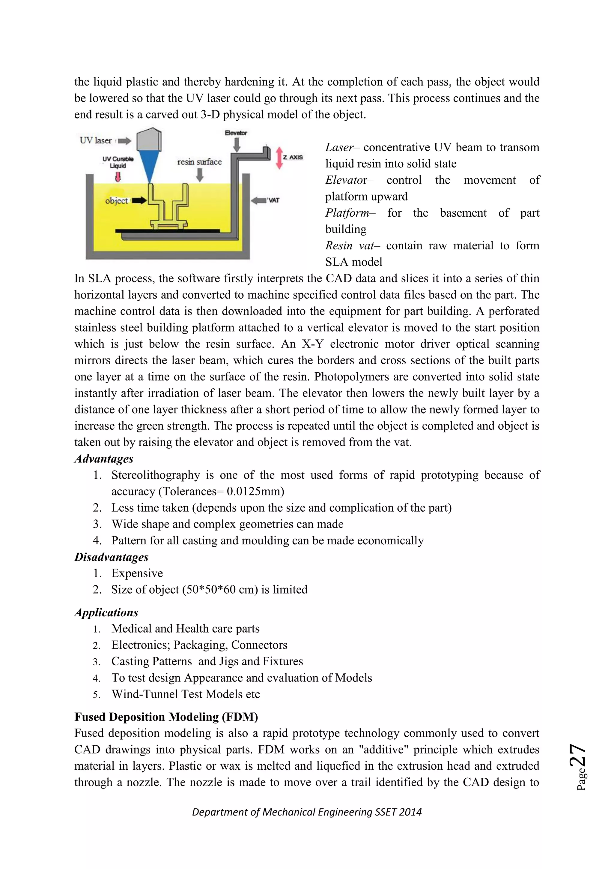
![Department of Mechanical Engineering SSET 2014
Page39
Various EDM electrodes
Brass: Brass was one of the first EDM electrode materials. It is inexpensive and easy
to machine. Not in use due to its high wear rate.
Copper: Copper electrode is conventional using for EDM process on its merits of
highly conductive, low cost, low wear ratio, good machinability, high finishing.
Tungsten: Due to the combination of its high density, tensile strength, and
highmelting point, tungsten had been the electrode material of choice for certain
limited EDM applications. But cuts much slower than Brass or Copper due its poor
electrical conductivity
Graphite Electrodes: Graphite is the preferred electrode material for EDM
applications.
o Graphite is faster than Copper in both roughing and finishing (machinability)
o Graphite usually wears less than Copper.
o Gives better Surface Finish:
Copper Tungsten
Copper graphite etc
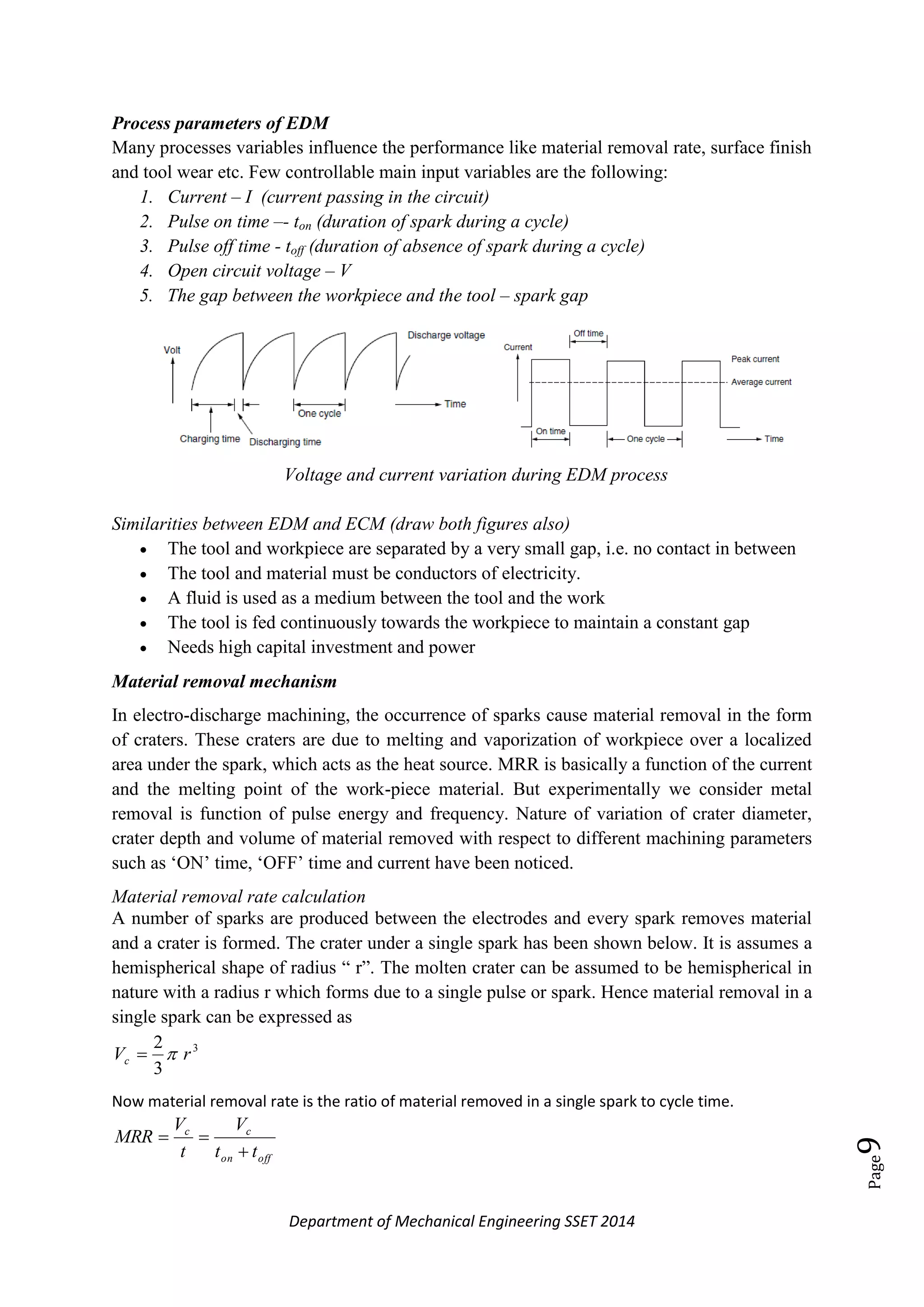
Performance of EDM processes is highly influenced on processes parameters given below
Discharge current (current Ip)
Discharge current is directly proportional to the Material removal rate. As current
density increases, the MRR is also increased and surface finish reduces.
Spark On - time (pulse time or Ton)
The duration of time (μs) the current is allowed to flow per cycle. Material removal is
directly proportional to the amount of energy applied during this on -time. This
energy is really controlled by the peak current and the length of the on - time.
Spark Off-time (pause time or Toff)
The duration of time (μs) between the sparks (that is to say, off -time). This time
allows the molten material to solidify and to be wash out of the arc gap. This
parameter is to affect the speed and the stability of the cut. Thus, if the off -time is too
short, it will cause sparks to be unstable.
Arc gap (or gap):
The Arc gap is distance between the electrode and work piece during the process of
EDM. It may be called as spark gap.
Voltage (V):
It is a potential that can be measure by volt it is also effect to the material removal rate
Comparison to other machining processes
Comparison with EDM
Extremely precise parts are possible [±0.0001" (±0.025mm)]
Very thick parts [over 12" (30 cm)] can be made
Intentional taper can be put into a part for die clearance and other uses
Comparing abrasive jet to laser
Very fast production in thin, non-reflective materials such as sheet steel.
Accuracy to ±0.001" (±0.025 mm) or better in thin material.](https://image.slidesharecdn.com/module5-150512113553-lva1-app6892/75/NON-TRADITIONAL-MACHINING-MATERIAL-ADDITION-PROCESS-as-per-MGU-syllabus-39-2048.jpg)

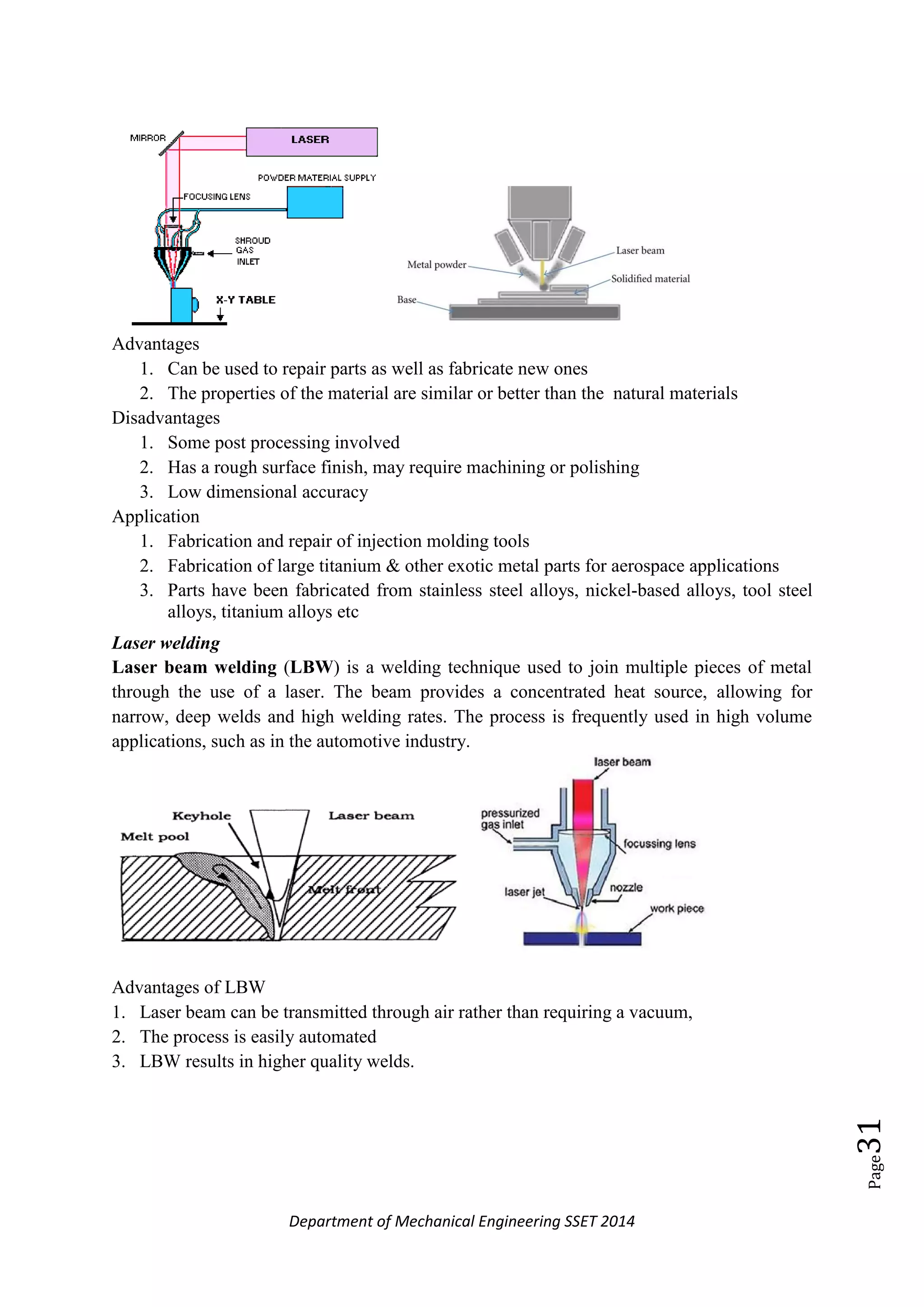
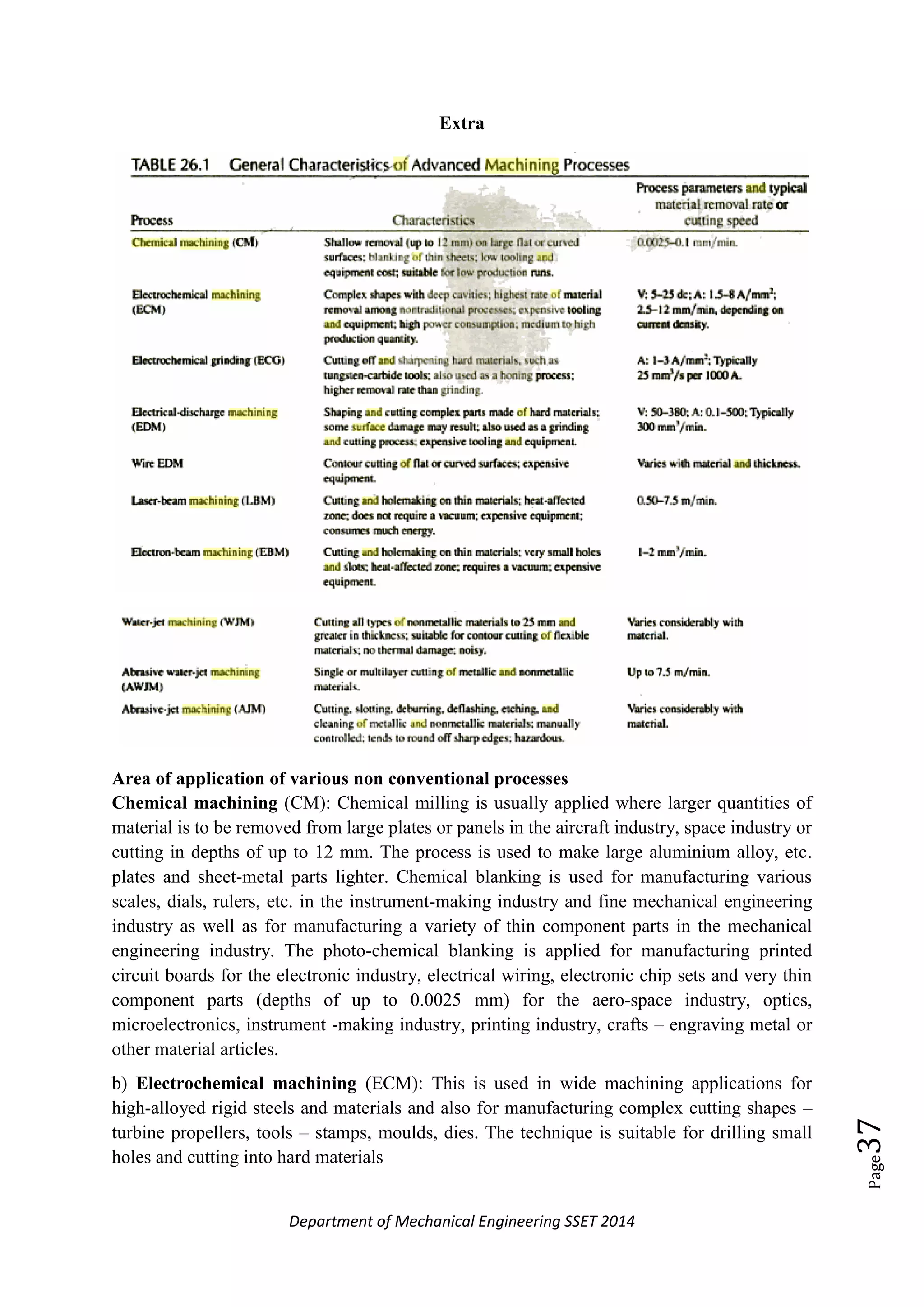
The document discusses non-conventional machining methods, highlighting their advantages such as the ability to machine hard materials and complex geometries without significant tool wear, which contrasts with conventional methods that involve direct tool contact and higher tool wear. It covers specific non-conventional methods like electrochemical machining (ECM) and electric discharge machining (EDM), detailing their processes, applications, advantages, and limitations. Additionally, it includes performance metrics and characteristics of these machining processes, providing insights into their operational effectiveness and suitability for various applications.
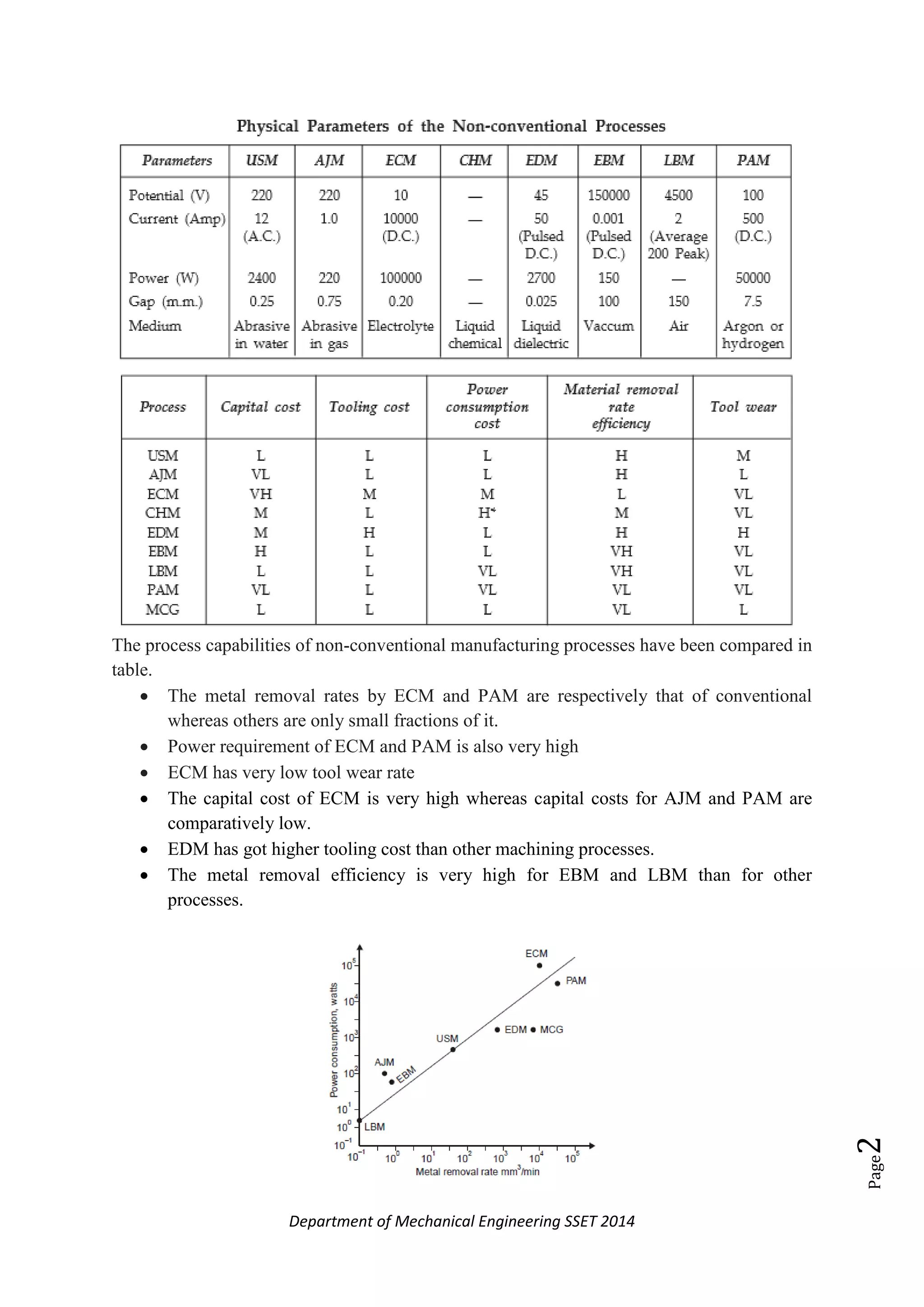
Non-conventional machining methods are essential for hard materials and complex geometries. Key processes: ECM, PAM, and EDM compare capabilities, cost, and efficiency.
Chemical machining, or etching, removes material using chemical attacks. It offers advantages like simultaneous processes and low costs, but has limitations in thick material removal.
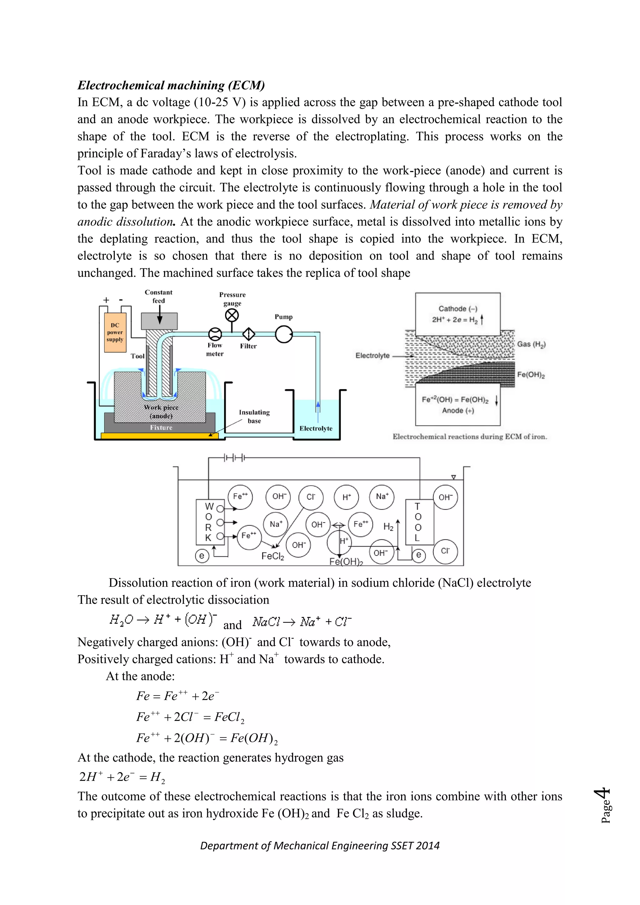
ECM uses electrochemical reactions for material removal with minimal wear. It efficiently machines hard materials but requires conductive workpieces and careful feed rate maintenance.
EDM utilizes electric sparks for material removal. It handles hard materials and complex shapes economically but has limitations in speed and precision.
WEDM employs a wire to cut materials efficiently with high precision. It’s suitable for detailed parts and various applications while limited to conductive materials.
Electron Beam Machining (EBM) and Laser Beam Machining utilize high-energy processes for precision material removal in diverse applications but have limitations in speed and cost.
Ion Beam Machining removes surface atoms through charged particles, while Ultrasonic Machining uses vibrations for cutting brittle materials. Both have specific advantages and constraints.
AJM utilizes high-speed abrasive particles for machining hard materials, offering smooth finishes but with low material removal rates and specific application limits.
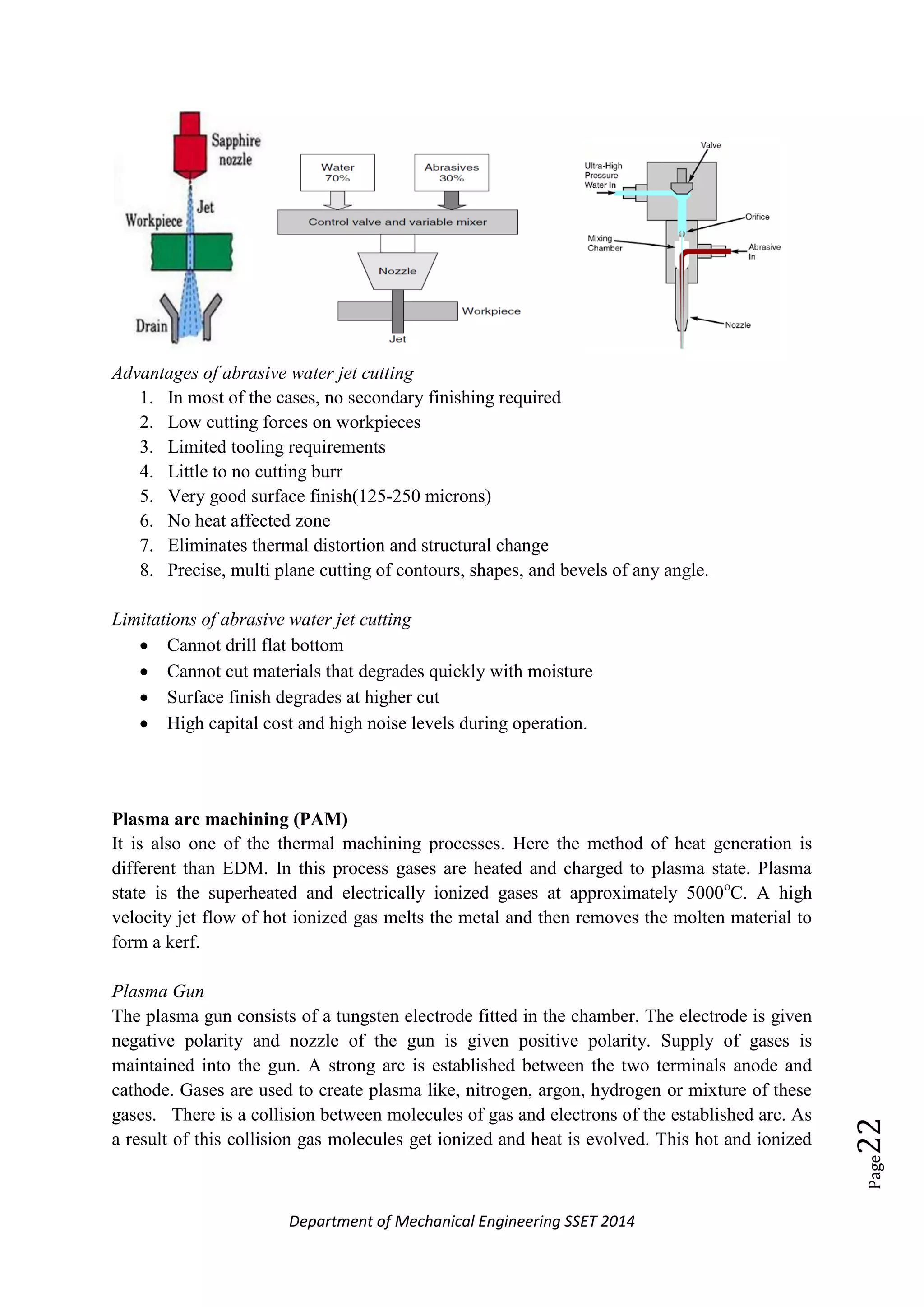
Water Jet Machining cuts softer materials effectively, whereas Abrasive Water Jet Machining increases versatility for harder materials with a high-speed cutting rate.
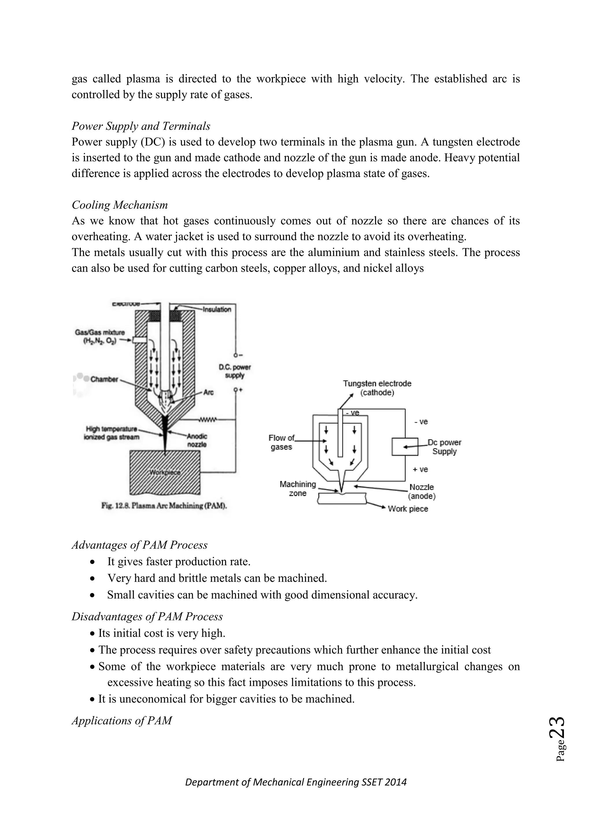
PAM employs a plasma jet for cutting and shaping, offering efficiency in hard materials but also facing issues of high costs and potential overheating. Rapid prototyping techniques like SLA and FDM enable fast, efficient part production through additive methods, reducing design flaws and enhancing communication.
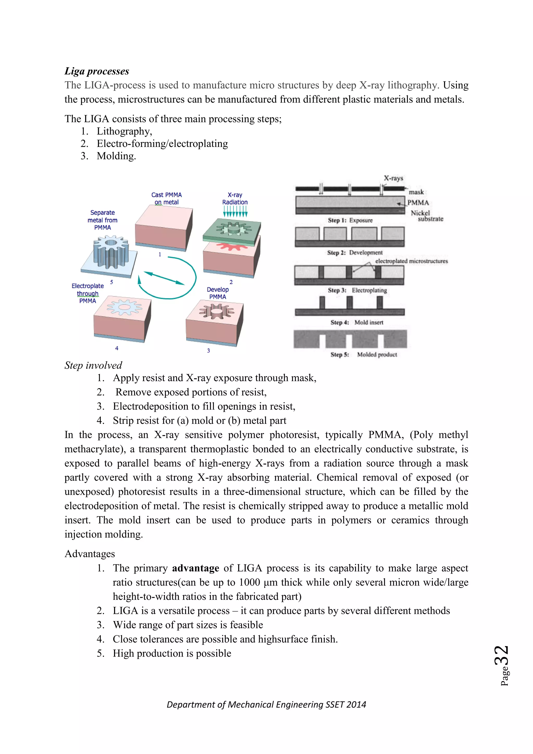
LIGA produces microstructures through lithography and plating, while high-energy forming methods use quick energy bursts to manipulate materials effectively.