


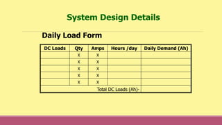
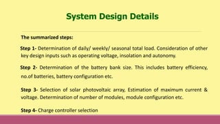
![DC Loads Qty Amps Hours /day Daily Demand (Ah)
X X
X X
X X
AC Sub-Total (Wh)
Continuous Watts = _____
Surge Est = _____
Inverter choice. : ____________________
[ ] / [ ] / [ ] + [ ] = ________
AC Sub-Total Efficiency Input Voltage DC Loads Daily Load(Ah)
Contd.
System Design Details](https://image.slidesharecdn.com/nrksolarpvcellsmodulearray-160831135913/85/Solar-PV-Cells-Module-and-Array-32-320.jpg)

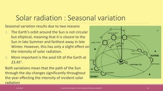
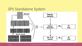
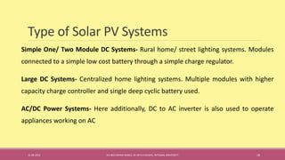
The document provides a comprehensive overview of solar photovoltaic (PV) technology, including the principles of solar energy capture, the structure and functioning of solar cells and modules, and the design considerations for PV systems. It discusses the photovoltaic effect, the components of solar cells, the electrical parameters, and the impact of light intensity, temperature, and atmospheric conditions on solar power generation. Additionally, it outlines the various types of solar PV systems, battery usage, and design factors critical for effective solar energy deployment.