SlideShare a Scribd company logo
1 of 35
Download to read offline
Department of Mechanical Engineering, SSET 2014
Page1
Module II
Heat generation in metal cutting
Almost all (90%-100%) of the mechanical energy consumed in a machining operation finally
convert into the thermal energy that in turn raises the temperature in the cutting zone. Heat
has critical influences on machining. To some extent, it can increase tool wear and then
reduce tool life, get rise to thermal deformation and cause to environmental problems, etc.
Sources of heat generation
The main heat sources of heat generations are shear zones.
1. Primary shear zone where the shearing of material takes place due plastic deformation.
(The energy required for shearing is converted into heat 80 to 85%)
2. Secondary deformation zone (chip – tool interface) where secondary plastic
deformation is due to the friction between the heated chip and tool takes place.
3. Tool-work interface -due to rubbing between the tool and finished surfaces (1 to 3%)
Dissipation of heat generated during the machining is as follows
 Discarded chip carries away about 60~80% of the total heat (q1)
 Workpiece acts as a heat sink drawing away 10~20% heat (q2)
 Cutting tool will also draw away ~10% heat (q3).
Effects of heat generation in machining
1. Affects tool life and wear rate
2. It affects strength and hardness of tool
3. Surface roughness (oxidation of machined surface and deformation)
4. Deformation of work and machine
5. High coolant circulation rate
6. Lower dimensional accuracy
7. Forms build up edge
Department of Mechanical Engineering, SSET 2014
Page2
Cutting temperature distribution
Cutting temperature is not constant
through the tool, chip and workpiece. It is
observed, that the maximum temperature is
developed not on the very cutting edge,
but at the tool rake some distance away
from the cutting edge. The temperature
field in the cutting zones is shown in the
figure.
Factors influencing Cutting temperature
1. Work material
a) Energy required (less energy means less temperature)
b) Soft and Ductility-cutting temperature is high
c) High thermal conductivity material reduces temperature
2. Tool geometry
a) Increased Rake angle reduces the cutting temperature
b) Increased cutting edge angle reduces the cutting temperature
c) Increased nose radius reduces the temperature slightly
3. Cutting condition
a. Cutting speed – most significant factor(Increases with speed)
b. Feed has less influence on cutting temperature
c. Depth of cut has least influence
4. Cutting fluid
 Cutting fluid reduces the temperature (reduces the friction and carries away the
heat)
From this figure is obvious, that any reduction of the cutting temperature will require
substantial reduction in either the cutting speed or cutting feed, or both (the effect of depth of
cut can be neglected). But cutting time and therefore production rate will decrease. To avoid
the problem, application of cutting fluid (coolants) is the solution.
Department of Mechanical Engineering SSET 2015
Page3
Tool temperature measurement
The power consumed in metal cutting is converted into heat. The magnitude of the
cutting temperature need to be known or evaluated to facilitate
1. Assessment of machinability (judged by cutting forces, temperature and tool life)
2. Design and selection of cutting tools
3. Proper selection and application of cutting fluid
4. Analysis of temperature distribution in the chip, tool and job
5. Evaluate the role of variation of the different machining parameters on cutting
temperature
The temperatures which are of major interests are:
etemperaturcuttingAverage
etemperaturerfacechiptoolAverage
etemperaturzoneshearAverage
avg
i
s
:
int:
:
:



Cutting temperature can be determined by two ways:
1. Analytically – using mathematical models (equations). This method is simple,
quick and inexpensive but less accurate and precise.
2. Experimentally – this method is more accurate, precise and reliable
The feasible experimental methods are:
1. Decolourising method – some paint or tape is pasted on the tool or job near the
cutting point and change in colour with variation of temperature may also often
indicate cutting temperature
2. Tool-work thermocouple – simple and inexpensive but gives only average
3. Photo-cell technique
4. Infra rad detection method
Brief description of few methods (Experimental)
Tool-work thermocouple
In a thermocouple two dissimilar but
electrically conductive metals are
connected at two junctions at different
temperature. The difference in
temperature at the hot and cold junctions
produce a proportional current which is
detected and measured by a milli-
voltmeter (mV). In machining, the tool
and the job constitute the two dissimilar
metals and the cutting zone functions as
the hot junction.
Department of Mechanical Engineering SSET 2015
Page4
Photo cell technique
This technique enables accurate measurement of the temperature along the shear zone
and tool flank. The electrical resistance of the cell, like PbS cell, changes when it is
exposed to any heat radiation. Holes are drilled at places where temperature is to be
measured. The cell receiving radiation through the small hole and change in resistance of
photo cell is measured which depends upon the temperature of the heat radiating source.
Infra red pyrometer method
Each body with a temperature above the absolute zero emits an electromagnetic radiation
from its surface, which is proportional to its intrinsic temperature. By knowing the
amount of infrared energy emitted by the object and its emissivity, the object's
temperature can often be determined. The basic design consists of a lens to focus the
infrared (IR) energy on to a detector, which converts to an electrical signal that can be
displayed in units of temperature
Tool material
With the progress of the industrial world it has been needed to continuously develop and
improve the cutting tool materials and geometry
1. To meet the growing demands of
high productivity, quality and
economy of machining
2. To enable effective and efficient
machining of the exotic materials
that are coming up with the rapid
and vast progress of science and
technology
3. For precision and ultra-precision
machining (micro and nano level
machining)
Reasons for development of new tool material
Department of Mechanical Engineering SSET 2015
Page5
Properties of Cutting Tool Materials
The cutting tool material should possess the following properties
1. Hot hardness
It is the ability of the tool material to retain its hardness and cutting edge at
elevated temperatures. Hot hardness can be increased by adding cobalt, chromium
molybdenum, tungsten and vanadium.
2. Wear Resistance
It is the ability of the tool material to resist wear when operating at high speeds.
The wear resistance can be increased by adding carbon and alloying elements.
3. Toughness
It is ability to resist shock and vibrations without breaking. This is particularly
important for interrupted cuts.
4. High thermal conductivity and specific heat
To conduct the heat generated at the cutting edge.
5. Coefficient of friction
The coefficient of friction between the chip and the tool should be as low as
possible in the operating range of speed and feed.
6. Favorable cost, easy to fabricate and easy to grind and sharpen.
7. It should have low mechanical and chemical affinity for the work material.
Selection of Cutting Tool Materials
The selection of cutting tool material will depend on the following factors:
1. Volume of production demanded
2. Cutting condition
3. Type of machining process
4. Physical and chemical properties of materials
5. Rigidity of the machine.
Classification of Tool Materials
1. High Carbon Steel
2. High Speed Steel
3. Stellite (Cast-Cobalt alloys)
4. Cemented Carbide
5. Coated Carbides
6. Ceramics
7. Cermet
8. CBN
9. Diamond
10. PCD
Department of Mechanical Engineering SSET 2015
Page6
Carbon Steel
Carbon steel, also called plain carbon steel, is a metal alloy, a combination of two main
elements, iron and carbon plus small amounts of manganese, phosphorus, sulfur, silicon
to improve the properties. These steels usually with less than 1.5 percent carbon and
generally categorized according to their carbon content. Generally, with an increase in the
carbon content from 0.01 to 1.5% in the alloy, its strength and hardness increases but
causes appreciable reduction in the ductility and malleability of the steel.
Plain carbon steels are further subdivided into groups:
1. Low Carbon Steels/Mild Steels contain up to 0.3% carbon
2. Medium Carbon Steels contain 0.3 – 0.6% carbon
3. High Carbon Steels contain more than 0.6% to 1.5% carbon
High carbon: It is very hard, wear resistant and difficult to weld. Used for cutting tools
Typical Composition carbon steel:
Carbon - 0.8 to 1.3%
Silicon - 0.1 to 0.4 %
Manganese 0.1 to 0.4 %
Department of Mechanical Engineering SSET 2015
Page7
General Characteristics/properties/advantages of high carbon steel
1. Suitable for low cutting speeds, limited to about 10 m/min using coolant supply.
2. Low hot hardness (Used where cutting temperature is below 200°C). Hardness
lost at 350°C).
3. Have good hardness and toughness (when heated and tempered).
4. Easy to forge and simple to harden.
5. Low cost
6. Can undergo heat treatment
Limitations of plain carbon steel
1. Plain-carbon steels have poor corrosion resistance
2. Plain-carbon steel oxidises readily at elevated temperatures.
3. There cannot be strengthening beyond a limit without significant loss in
toughness and ductility.
Application
Used to make reamers, hacksaw blades, taps and dies etc
High Speed Steels
The term `high speed steel' was derived from the fact that it is capable of cutting metal at
a much higher rate than carbon tool steel and continues to cut and retain its hardness even
when the point of the tool is heated to a low red temperature. The alloying elements
increase the strength, toughness, wear resistance and cutting ability.
The basic composition of HSS
18% W
4% Cr
1% V
0.7% C and rest is Fe
Properties /features
1. HSS can operate at cutting speeds 2 to 3 times higher that of high carbon steel.
Cutting speed up to 30 m/min
2. Excellent toughness- It takes shocks and vibration during cutting
3. It retains hardness at elevated temperatures in the range of 550°C to 600°C.
4. Higher metal removal rates.
5. Less Costly
Application
1. Used to make lathe tools, drills, reamers, shaper tools, slotting tools, farming
equipments and compression springs etc.
Coated HSS
A very thin coating of 5-7µm thickness of wear resistant material on conventional HSS
tool is provided to improve its performance. Vapor chemical deposition technique is used
to give the thin coatings of titanium or zirconium carbide and nitrides on HSS tools.
Department of Mechanical Engineering SSET 2015
Page8
Stellite
Composition
48-53% 30-33% 10-20% 1.5-2.0%
Co Cr W C
 Manufacturing Process- Casting
 Hot hardness- 760ºC
 Cutting Speed -45 m/min
 Higher tool life compare to H.S.S.
 Lower toughness/brittle
Cemented Carbides
The Cemented Carbides are a range of composite materials, which consist of hard carbide
particles bonded or cemented together by a metallic binder. Pure tungsten carbide powder
and carbon is mixed and then mixed with binder at high temperature and manufactured
by powder metallurgy methods. Its unique combination of strength, hardness and
toughness satisfies the most demanding applications. It is usually used as tool inserts
brazed on to steel holders. Example of tool: Tungsten carbide, titanium carbide etc
Composition of tungsten carbide tool
W C Co
94% 6% cobalt (Binder)
Properties
1. High hardness and wear resistance
2. Maximum limiting cutting temperature -1200 ºC
3. Cutting Speed -100 m/min so High material removal rate
4. High Tool life
5. Gives better surface finish
6. Easy to manufacture with powder metallurgy methods (low cost)
Application
 Used in machining tough materials such as carbon steel or stainless steel, as well as in
situations where other tools would wear away, such as high-quantity production runs.
Coated tungsten carbide
Thin film of coating of hard and wear resistive materials like Titanium Nitride (TiN),
Titanium Carbide (TiC) and Aluminium Oxide (Al2O3) etc is deposited on surface to
improve the life and service quality of tool. Chemical Vapor Deposition (CVD) or
Physical Vapor Deposition (PVD) technique is used for coating deposition.
Properties
1. High hot hardness-retains cutting edge sharpness at high temperature
2. High cutting speed -150 to 250 m/min
3. High Tool life (2 to 3 times higher than carbide)
4. Reduction of cutting forces and power consumption
5. Improvement in product quality - Chemically more stable
Department of Mechanical Engineering SSET 2015
Page9
Applications:
1. Widely used for high speed machining
2. Machining of very hard materials
Ceramics or Oxide tool
Ceramic tool materials consist primarily of fine grained aluminium oxide, cold-pressed
into insert shapes and sintered under high pressure and temperature.
1. They are hard, retain their hardness at high temperatures of 1700°C.
2. High Cutting Speed -200 to 400 m/min (Used for high speed machining )
3. Good surface finish and dimensional accuracy in machining steels.
4. They have longer tool life
5. Chemically more stable (less tendency to adhere to metals during machining so
low build up edge)
Limitation:
1. Poor Toughness: They are extremely brittle and can’t take shock and vibrations
(not suitable for interrupted cut)
2. Unreliable (sudden fail) and also high rigidity set up is required
Application
Used for cutting carbon steel and HSS
Cermets
A cermet is a composite material composed of ceramic and metallic materials. As the
name suggests, cermets (derived from ceramics and metals) combine the positive
properties of two material groups. Cermet is a cutting tool material composed mainly of
TiC (Titanium Carbide) and TiN (Titanium Nitride) bonded together with a nickel
(metal) binder.
The objective to combine the properties of ceramics, such as
1. Hardness
2. Resistance to oxidation
3. Heat resistance
1. Toughness properties of metals,
2. Impact strength
in order to create an ideal cutting material, “cermet”
Properties (Properties comes between carbide and ceramics tool)
1. High hardness and more chemically stable, hence more wear resistant
2. High hot hardness greater than carbide tool and less than ceramics tool
3. High thermal shock resistance
4. Excellent surface finish at very high cutting speed
5. High tool life
Application: Used for cutting steel and cast iron at high cutting speed.
Department of Mechanical Engineering SSET 2015
Page10
Sialon
Sialons are ceramics based on the elements silicon (Si), aluminium (Al), oxygen (O) and
nitrogen (N. They are formed when silicon nitride (Si3N4), aluminium oxide (Al2O3) and
aluminium nitride (AlN) are reacted together. The materials combine over a wide
compositional range.
Sialon ceramics are a specialist class of high-temperature refractory materials,
1. High strength,
2. Good thermal shock resistance and
3. Exceptional resistance to wetting or corrosion.
4. Oxidation resistance
CBN: cubic born nitride
CBN tools are very effective at machining most steels and cast irons, but they are also
very expensive. It is the second hardest material known (second to diamond). CBN is
used mainly as coating material because it is very brittle. Boron nitride has the formula
(BN)n, (n is a very large number, but the empirical formula is BN). In the cubic form of
boron nitride, alternately linked boron and nitrogen atoms form a tetrahedral bond
network, exactly like carbon atoms do in diamond.
Properties
1. CBN is an excellent abrasive resistance to cut
2. Very hard and high hot hardness -. can efficiently machine steel
3. Long Tool Life: provide uniform hardness and abrasion resistance in all directions.
4. High Material-Removal Rates: 700 -800 m/min
5. Lower cutting cost
Application
1. Used for roughing and finishing operations
2. Machining of hard steel
3. High speed finish machining of hardened steel and super alloys
Diamond
Diamond has most of the properties (hardest) desirable in a cutting tool material.
Diamond also has high strength, good wear resistance and low friction coefficient.
Diamond is composed of pure carbon atoms, arranged in a very special crystal orientation
that gives it its unique physical properties. Single crystal diamond tools have been mainly
replaced by polycrystalline diamond (PCD). This consists of very small synthetic crystals
fused by a high temperature high pressure process to a thickness of between 0.5 and 1mm
and bonded to a carbide substrate.
1. It is the hardest cutting material.
2. It has low coefficient of friction, high compressive strength and extremely wear
resistant.
3. Used for machining very hard material such as glass, plastics, ceramics etc.
Department of Mechanical Engineering SSET 2015
Page11
4. It produces very good surface finish at high speeds with good dimensional
accuracy. Best suited for light cuts and finishing operations.
5. It can resist upto a temperature of 1250°C.
6. High cutting speed (300 to 1000 m/min)
Diamond coated tool
The tool life of cemented carbide cutting tools is greatly improved by diamond coating,
and typically more than 10 times the tool life is obtained. Diamond films are usually
deposited more than 10 pm thick to make tool life longer, since tool life is directly related
to film thickness. Coats tools with polycrystalline diamond, applied with a CVD process.
The diamond coating can withstand the abrasiveness of these materials. High cutting
speed, accuracy of cut and dry cut is possible.
Comparison of diamond and CBN
Diamond and CBN have the same crystal structure, with diamond consisting of pure
carbon, whilst CBN is made up of the elements boron and nitrogen. In contrast to
Diamond, CBN has no carbon atoms, making it suitable for machining steel. CBN is
better suited for machining the following materials:
 Hardened steel over approx. 54 HRc hardness and High-speed steel
 Stellite and Nickel-based special alloys
Diamond is generally used for machining non ferrous materials. Steel has a high affinity
to carbon. Since Diamond consists of pure carbon, it is not suitable for machining steel.
Indexable inserts
A tipped tool generally refers to any cutting tool where the cutting edge consists of a
separate piece of material, either brazed, welded or clamped on to a separate body.
The advantage of tipped tools is only a small insert of the cutting material is needed to
provide the cutting ability.
Advantages of tipped tool
1. Small size insert makes manufacturing easier
2. Reduces cost because the tool holder can be made of a less-expensive and tougher
material.
3. Easy to handle
The indexable insert technique, meaning a replaceable cutting edge, or so called insert,
was placed in the toolholder. Inserts are removable cutting tips, which means they are not
brazed or welded to the tool body. This saves time in manufacturing by allowing fresh
cutting edges to be presented periodically without the need for tool grinding and setup
changes.
Department of Mechanical Engineering SSET 2015
Page12
Tool failure
Cutting tools generally fail by:
1. Gradual wear of the cutting tool at its flanks and rake surface.
2. Mechanical breakage and chipping due to excessive forces and shocks.
3. Plastic deformation of cutting edge due to intensive stresses and temperature.
The last two modes of tool failure are very harmful and need to be prevented by using
suitable tool materials and geometry depending upon the work material and cutting
condition. But failure by gradual wear, which is inevitable, cannot be prevented but can
be slowed down only to enhance the service life of the tool.
It is considered that the tool has failed or about to fail by one or more of the following
conditions:
1. Total breakage of the tool or tool tip(s)
2. Massive fracture at the cutting edge(s)
3. Excessive increase in cutting forces or vibration
4. Average wear (flank or crater) reaches its specified limit(s)
5. Excessive vibration and or abnormal sound (chatter)
6. Dimensional deviation beyond tolerance
7. Rapid worsening of surface finish
Tool wears mechanism / mode of wear
For the purpose of controlling tool wear one must understand the various mechanisms of
wear that the cutting tool undergoes under different conditions.
The common mechanisms of cutting tool wear are:
1) Mechanical wear
a. abrasion,
b. adhesion,
c. chipping
d. fatigue
2) Thermo-chemical wear
a. diffusion wear
3) Chemical wear
a. corrosion
b. oxidation
Abrasive wear: wear due to the abrasive
action between the chip and tool as the
chip passes over the rake surface of tool.
Department of Mechanical Engineering SSET 2015
Page13
Adhesive wear: the tool and the chip
weld together at contacts, and wear
occurs by the fracture of these welded
junctions.
Welding is due to
 Friction
 High temperature
 Pressure
Fatigue wear: Due to friction while cutting, compressive force will be produced in one
side and tensile force on other side. This causes the crack formation on the surface of tool
and fails.
Chipping of tool: It refers the breaking away of small chips from the cutting edge of tool
Diffusion wear: When a metal is in
sliding contact with another metal the
temperature at the interface is high. The
high temperature allows the atoms of
hard material to diffuse into softer
material matrix. At high temperature
there is an intimate contact between the
chip and the tool rake face. Atoms of the
softer metal may also diffuse into harder
medium, thus weakening the surface of
harder material. Diffusion phenomenon
is strongly dependent on temperature
Oxidation wear: Oxidation wear is the result of reaction between tool face material and
oxygen present in the vicinity.
Corrosion wear: may be included in wear phenomenon
Gradual or progressive tool wear / (types of wear)
a) Flank wear
b) Crater wear
c) Nose wear
d) Plastic deformation of tools
The main wears in cutting tool are
1) Crater wear –occurs on top rake face due to diffusion and friction between tool
and chip. Crater wear dominates at high speeds.
2) Flank wear –occurs on flank (side of tool) due to abrasive rubbing between the
tool flank and the newly generated work surface. Flank wear dominates at low
speed
3) Nose wear is the rounding of a sharp tool due to mechanical and thermal effects
Department of Mechanical Engineering SSET 2015
Page14
The tool wear depends on a number of factors such as:
1. Hardness and type of tool material.
2. Cutting tool geometry.
3. Feed and depth of cut.
4. Cutting fluid.
5. Material and condition of work-piece.
6. Dimensions of the work-piece.
Effects of tool wear
Tool wear causes the tool to lose its original shape and lose its cutting efficiency. Tool
wear is a time dependent process. As cutting proceeds, the amount of tool wear increases
gradually. But tool wear must not be allowed to go beyond a certain limit in order to
avoid tool failure.
1. Increase the cutting force
2. Increase the surface roughness
3. Decreases dimensional accuracy
4. Increase the cutting temperature
5. Creates vibration
6. Reduce the quality of work
7. Increase the cost and lower the cutting efficiency
Department of Mechanical Engineering SSET 2015
Page15
Tool wear criteria/tool life criteria
In practical situation, the time at which a tool ceases to produce work-pieces with desired
size, surface quality and acceptable dimensional tolerances, usually determines the end of
tool life. In most cases the tool wears gradually and the roughness of the machined
surface becomes too high, cutting forces rise and cause intolerable deflections or
vibrations etc. As the tool wear rate increases, the dimensional tolerances can not be
maintained. When the wear reaches a certain size, it will accelerate and may lead to a
sudden failure of the edge.
In economical machining under normal cutting condition, wear on the flank is usually the
controlling factor. So flank wear is the criteria (ISO test) normally used to assess the tool
life. Some wear is inevitable. (flank wear is normally the most consistent form of wear
which is easy measurable). It is measured by the width of flank wear (VB/FW shown in
figure) is used to define the tool life. If the amount of flank wear exceeds some critical
value (VB -0.3 to 0.5mm) the excessive cutting force may cause tool failure.
Other failure criteria based on crater wear, notch wear, surface finish and dimensional
variations also used to define the tool life. When the cutting edge of the tool reaches one
of the tool life criterion, the tool should be replaced by a new one or sending it for
regrinding.
Stages of tool wear
Rapid initial wear as the new tool is introduced on to the work. Then wear rate reduces
and takes a uniform rate and finally wear exceeds a limit it gets failed
The width of flank wear land is usually taken as a measure of the amount of wear land
deciding the wear allowable before regrinding or disposal of tool (measured using tool
maker’s microscope).
 Region AB- rapid wear rate due the initial broken down of cutting edge
 Region BC- uniform wear rate
 Region CD- increasing rate
Department of Mechanical Engineering SSET 2015
Page16
Tool Life
A tool cannot cut for an unlimited period of time. After using for a certain period of time,
it ceases to cut satisfactorily unless it is re-sharpened. It has a definite life. The tool life
maybe defined as the time elapsed (actual cutting time) between two consecutive
sharpening of the cutting tool. The tool life can be measured in the following ways:
1. Volume of material removed between two successive grindings.
2. Number of pieces machined between two successive grindings.
3. Total time of operation.
4. Equivalent cutting speed.
Factors affecting Tool Life (same factors of machinability)
1. Tool and Work Material
2. Tool Geometry
3. Cutting Speed
4. Feed and Depth of Cut
5. Cutting Fluid
6. Rigidity of tool, work and machine.
7. Area of cut
Tool Life Equation (Taylor’s Equation based on Flank Wear)
Tool life of any tool for any work material is governed mainly by the level of the
machining parameters i.e., cutting velocity (VC), feed (f) and depth of cut (t1). Usually
flank wear (VB) is taken as the criteria for fixing the wear limit for tool change and its
dependence on cutting velocity are schematically shown below:
 The tool life obviously decreases with the increase in cutting velocity keeping other
conditions kept constant.
 Life of the tools T1, T2, T3, and T4 are plotted against the corresponding cutting
velocities V1, V2, V3, and V4, a smooth curve like a rectangular hyperbola is found.
 By plotting VC and T and the log scale the following plot was obtained.
Department of Mechanical Engineering SSET 2015
Page17
Taylor derived the tool life equation,
VTn
= C or V1T1
n
= V2T2
n
=C
Where,
T = tool life in minutes
V = cutting speed in m/min
n = index which depends on tool and work-piece
= 0.1 to 0.5 for HSS tools
= 0.2 to 0.4 for carbide tools
= 0.4 to 0.6 for ceramic tools
C = constant. It is numerically equals to cutting speed that gives a tool life of one
minute. The value of C depends on tool-work material and cutting environment
(feed and depth of cut).
2211 loglogloglog TnVTnV 
12
21
loglog
loglog
TT
VV
n



Note: If the higher cutting speed is permitted by a tool for the same life, we can say that
the tool is having better cutting properties and it will be more productive.
Department of Mechanical Engineering SSET 2015
Page18
Effect of tool life on rake, clearance angle, cutting time and temperature
 Tool life increases with increase of rake angle for the given cutting speed. Increase
of rake angle decreases the cutting force and temperature.
 As the clearance angle increases, the tool chip contact area increases which reduces
the cutting temperature and wear rate ultimately increases the tool life.
 Increases of nose radius also increases the life to a extent
 Wear increases with cutting temperature. All types of wear accelerate with increase
of temperature (mechanical, chemical and diffusion wear)
 Cutting time- tool wear is a time dependent factor. As cutting proceeds, the amount
of tool wear increases gradually.
There is optimum value of rake and clearance angle which gives maximum tool life
Department of Mechanical Engineering SSET 2015
Page19
Machineability
It can be defined as the ease with which a material can be machined by a given tool under
a given set of conditions. Suppose it is states as material A is more machinable than
material B, then it means that:
1. Tool wear rate is less when machining material A
2. Better surface finish is obtained for material A.
3. Less power is consumed during the machining of material A.
Factors affecting machinability
1. Work variables
a) Chemical composition of the workpiece material.
b) Microstructure of the workpiece material.
c) Mechanical properties like ductility, brittleness, toughness etc.
d) Physical properties of the work material.
e) Method of production of the work material.
2. Tool variables
a) Geometry of the tool.
b) Tool material
c) Rigidity of the tool.
d) Nature of engagement of the tool with the work.
3. Machine variables
a) Rigidity of the machine
b) Power and accuracy of the machine tool.
4. Cutting conditions
a) Cutting speed
b) Feed
c) depth of cut
d) cutting fluid
Evaluation or assessment of Machinability (Criteria for evaluating machinability)
1. Tool life for a given cutting speed and tool geometry.
2. Material Removal Rate.
3. Magnitude of cutting forces and power requirement.
4. Quality of the surface finish of the work material.
5. Accuracy of dimensions of the workpiece.
6. Ease of chip disposal
7. Shape and size of chips formed.
8. Heat generated during the cutting process.
9. Power consumption per unit volume of material removed.
Department of Mechanical Engineering SSET 2015
Page20
Advantages of high machinability
1. Good surface finish can be obtained.
2. Higher cutting speed can be employed.
3. High Material Removal Rate
4. Less tool wear.
5. Less power consumption.
Machiability Index
It is a quantitative measure of machinability. It is used to compare the machinability of
different metals. The machinability index of free cutting steel is arbitrarily fixed as 100%.
Thus for other metals machinability index is given by:
lifetooluteforsteeldardsofspeedCutting
lifetooluteformaterialofspeedCutting
IIndexityMachinabil
min20tan
min20
, 
Methods to improve the machinability
The machinability of the work materials can be improved, by the following ways:
 Favourable change in composition, microstructure and mechanical properties by
mixing additive(s) in the work material and appropriate heat treatment
 Proper selection and use of cutting tool material and geometry depending upon the
work material and the significant machinability criteria under consideration
 Optimum selection of cutting parameters
 Proper selection and appropriate method of application of cutting fluid depending
upon the tool – work materials
 Proper selection of special techniques like hot, cryogenic machining etc,
 By changing the method of work material production, eg: cold worked material
shows higher machinability
Machinability of Titanium, Aluminium and Copper alloys
Materials with good machinability require little power to cut, can be cut quickly, easily
obtain a good finish, and do not wear the tooling much.
Titanium
The machinability of titanium and its alloys is generally considered to be poor owing to
several inherent properties of the materials. The machinability index of titanium is about
30% or less (0.3). Machininability involves careful selection of tool geometry and speed.
Poor machinability may due following properties
 Titanium is very chemically reactive
 Tendency to weld to the cutting tool during machining, thus leading to chipping
 Its low thermal conductivity increases the temperature which affects the tool life
and build up edge
Department of Mechanical Engineering SSET 2015
Page21
Aluminum alloys
Compared to other construction materials, aluminium is easy to machine and gives good
tool life. Carbide tool gives 600m/min cutting speed.
 In general, the specific cutting force for aluminium is about 30% that of steel.
 Most aluminum alloys are easily machined and yields greater tool life and
productivity.
 Machinability index of aluminium is about 300 to 1500% (Excellent machinability)
 Aluminium is machined using tools made of tool steel, high-speed steel, cemented
carbides and diamond
Although readily machinable, aluminum has a high coefficient of friction and high
thermal coefficient of expansion. This means a special approach is required including the
use of polished tools with different tool geometry and good lubrication to avoid thermal
stress. Chips are of the continuous type. The primary tooling concerns when machining
aluminum are: minimizing the tendency of aluminum to stick (BUE) to the tool cutting
edges and poor surface finish
Copper alloys
All coppers and copper alloys can be machined accurately, cheaply and to a good
standard of tolerances and surface finish. Machining copper alloys is considerably easier
than machining steels of the same strength.
 Significantly lower cutting forces
 The machinability rating of this alloy is 1.6 to 2 (160 to 200%)
 Brass is more easy to machine than bronze
Tools used for machining
 Usually tungsten carbide-cobalt, coated HSS, CBN or PCD cutting tools are used.
Effect s of cold working on machinability
Cold working of work materials results in many improvements on its properties resulted
in better machinability. A cold worked material gives following characteristics.
1. Improved surface finish
2. Controlled dimensional tolerance and concentricity
3. Improve machinability
Economics of Metal Cutting
The primary aim is to produce satisfactory parts at the lowest possible cost and highest
possible production rate. As the cutting speed increases the MRR is high giving low
cutting cost, but the tool life will be shorter and consequently high cutting cost per piece.
At some intermediate cutting speed, the tool cost will be minimum. The tool life
corresponding to this speed is economical tool life.
The total cost per piece is based on:
 Non productive cost
Department of Mechanical Engineering SSET 2015
Page22
 Cutting or machining cost
 tool changing cost
The machining cost per component is made up of a number of different costs. Non-
productive cost per component includes the cost of loading and unloading component,
and other non-cutting time costs.
Select speed to achieve a balance between high metal removal rate and suitably long tool
life . Mathematical formulas are available to determine optimal speed
Two alternative objectives in these formulas:
1. Maximum production rate
2. Minimum unit cost
Maximizing production rate = minimizing cutting time per unit
Cutting force measurement
The forces generated by a machining process can be monitored to detect a tool failure or
to diagnose and controlling the process parameters, and in evaluating the quality of the
surface produced. There are many force measurement systems, such as strain gages,
inductive and capacitive systems. During machining, the cutting tool exerts a force on the
work piece. The cutting force includes tangential, feed and radial force. These force
components can be measured with a dynamometer.
Quartz crystals experience the piezoelectric effect which produces electric charge when
the material is deformed. The cutting force is measured either directly gauging the
deformation caused or by sensing the deformation with a transducer or converting it.
Department of Mechanical Engineering SSET 2015
Page23
Cutting Fluid
During a metal cutting operation heat is generated due to plastic deformation of the metal
and friction of the tool-work interface. The increase in temperature reduces the hardness
of the tool. This leads to tool failure. Cooling the work prevents the excessive thermal
distortion of the work and cooling the tool helps to increase tool life
Cutting fluid is used to carry away the heat produced during the machining and
reduce the friction between the chip and the tool. Cutting fluids in the form of a liquid are
applied to the chip formation zone to improve the cutting conditions.
If the tool has low value of hot-hardness, there is appreciable increase in tool life as result
of cutting fluid supplied to the cutting zone. In the case of carbides and oxides which
have high value of hot-hardness, cutting fluid has negligible effect on the tool life.
Functions of the Cutting Fluid
1. To cool the tool and work during machining (dissipate heat)
2. To lubricate ( to reduce friction)
a. It reduces the power consumption
b. It prevents the formation of BUE
c. Increases tool life
d. Reduces heat generated at the tool chip interface
3. To protect the finished surface from corrosion.
4. To cause the chips break into small pieces.
5. Chips are disposed off easily
6. To improve surface finish
Properties of Cutting Fluid
1. Good lubricating properties to reduce frictional and the power consumption.
2. High heat absorbing capacity (high specific heat)
3. It should high heat conductivity.
4. High flash point.
5. Should be non corrosive to work and tool.
6. It should have low viscosity to permit free flow of liquid.
7. Should not lose its properties when exposed to heat.
8. It should not react with the work piece
9. Should be economical in use.
Types of cutting fluids
a) Water based cutting fluid
b) Straight cutting oils
c) Synthetic cutting fluid (from chemicals)
Water based Cutting Fluids
To improve the cooling and lubricating properties of water, the soft soap and mineral oils
are added to it. Soluble oils are emulsions composed of around 80% of water, remaining
soap and mineral oils. The soap acts as the emulsifying agent which breaks the oil into
particles to minute particles to disperse them throughout water.
Department of Mechanical Engineering SSET 2015
Page24
It has got excellent cooling properties at low cost and has got some lubricating effect
between the chip and the tool. By varying the proportion of water cutting fluids with
wide range of cooling and lubricating properties are obtained. Water bases cutting fluids
may be adopted for medium and high speed applications. This is due to the fact that at
low speeds the heat transfer characteristics may be low but lubricity should be high. At
high speeds good heat transfer characteristics are more desirable.
Straight or oil Based cutting fluids
Straight or oil based cutting fluids means undiluted or pure oil based fluids. These oils
have good lubricating properties but poor heat absorption quality. The heat transfer rates
by their application are the lowest among cutting fluids. Thus they are only suitable for
low cutting speeds. Used for heavy cutting process like broaching, threading and gear
etc. Poor cooling and smoke formation are the disadvantages
They can be classified into the following groups:
1. Mineral oils
2. Fatty oils
3. Combination and mineral and fatty oils
Oil with additives
a) The beneficial effect of mineral oils can be improved with the help of additives,
which are generally compounds of sulphur and chlorine.
b) Other additives may also be used to improve stability and anti rust properties.
Selection of Cutting Fluids : The guidelines for selection of cutting fluids are:
a) Type of machining process
b) Based on tool and work materials
c) Based on cutting condition like speed, feed etc
d) Method of application of fluid
e) Temperature involved
Methods of application
a) Flooding – cutting fluid is flooded over the cutting area
b) Jet – cutting fluid under pressure with nozzle
c) Mist – mixed with compressed air
Oil with extreme pressure characteristics may be adopted for low speed cuts.
Example: Machining of aluminium using water based cutting fluid
Alloy steel uses water based and mineral oil etc
Cast iron – dry machining (no cutting fluid is needed as free graphite in cast iron)
************************************************
Department of Mechanical Engineering SSET 2015
Page25
Problems
Example 1: A lathe running at a speed of 4000 rev./min is cutting Mild Steel with a
H.S.S. tool. The spindle speed is reduced to 3000 rev./min. calculate the percentage
change in tool life
Given,
V1 = Initial cutting speed. V2 = Reduced cutting speed.
T1 = Tool life at V1. T2 = Tool life at V2.
Take, n = 0.125
VTn
= C
VT0.125
= C
So T1
0.125
= ( C / V1 )
And T2
0.125
= ( C / V2 )
(T1/T2)0.125
= (C/V2)
(C/V1)
(T2/T1)0.125
= C x V1
V2 x C
(T2/T1)0.125
= V1
V2
(T2/T1) = 9.99
T2 = 9.99xT1
This shows that reducing cutting speed by 25% increases tool life by nearly 10
times (under the cutting conditions of this particular setup).
Problem 2: In the previous example, for instance, if it were to be observed that the initial
tool life (T1) was 4 hours and cutting speed 30m/min., then: -
VTn
= C
30 x (4x60(mins))0.125
C = 59.5
Department of Mechanical Engineering SSET 2015
Page26
Problem 3
If the value of n for mild steel workpiece material and carbide tool material is 0.1 then at
the same cutting speed of 30 m/min:
VTn
= C
30 x T0.1
= 59.5
T0.1
= 59.5
30
T = 941 minutes
As opposed to 240 minutes using the H.S.S. tool.
Problem 4
If in turning of a steel rod by a given cutting tool (material and geometry) at a given
machining condition ( feed f and depth of cut t1) under a given environment (cutting fluid
application), the tool life decreases from 80 min to 20 min. due to increase in cutting
velocity, VC from 60 m/min to 120 m/min., then at what cutting velocity the life of that
tool under the same condition and environment will be 40 min.?
Department of Mechanical Engineering SSET 2015
Page27
Problem 5
During a tool life-cutting test on HSS tool material, following data were recorded.
Calculate the values of n and C of taylor’s equation
Department of Mechanical Engineering SSET 2015
Page28
Department of Mechanical Engineering SSET 2015
Page29
Module II Question
1. Define machinability.****
2. Define machinability index.****
3. What do you mean by machinability ? Explain the method of determining
machinability of a material and the factors affecting machinability.*****
4. Define machinability. How it is expressed? State the factors affecting the
machinability of material.******
5. Explain the term machining economics and machiuability index.
6. The machinahility index of SS and of Al alloys is 30 and 1500 respectively. What
does it signify
7. Discuss the functions effecting machinability.
8. What is the effect of cold working in machinability?
*****************************************************************
9. What the properties are of required for a tool material? Give the details of some
common tool materials.
10. Present the developments in cutting tool materials in the last decade
11. What are the desirable characteristics of cutting tool materials? Describe how they
are satisfied in High Speed Steel tools. **
12. Discuss the factors affecting tool life and discuss requirements of tool material to get
reasonable tool life.
13. Discuss briefly various cutting tool materials.
14. Explain any two cutting tool material characteristics.
15. What is HSS and what are its advantages '?
16. When do you use the diamond as cutting tool material?
17. What are the factors affecting tool life and how it is improved? ***
18. Define tool life and state the factors- affecting tool life. ***`
19. Define tool life and explain how it is accessed in metal cutting operations.
20. Explain the relationship between tool life and cutting speed.**
21. What is Taylor tool life equation? Explain economic cutting speed.**
22. Define tool life. Derive Taylor's relationship for cutting speed-tool life.**
23. What is the effect of cutting speed on tool life
24. Classify the different types of tool life tests
25. Discuss the significance of too life.
26. Discuss economic tool life.
27. A 25 mm. dia steel bar was turned at 3000 r:p.m. using HSS tool. Tool failure
occurred after 10 minutes. When the speed was reduced to 250 r.p.rn., the tool failed
in 52.5 minutes. Assuming Taylor equation is valid, find the expected tool life at a
speed of 275 rpm.
28. For a HSS tool cutting mild steel at 20 m./min, the life is 4 hours. Calculate its life
when the cutting speed is increased to 24 m./min:
29. What is the tool life of a HSS tool 10-15-6-6-18-14-2 working at 50 m/min?
Department of Mechanical Engineering SSET 2015
Page30
30. What are the factors influencing tool wear? Explain how the process parameters can
be controlled to reduce wear and improve life.
31. Explain the mechanism of tool wear. How can it be measured?**
32. State the reasons responsible for tool failure.**
33. Name the different types of tool wear and explain. briefly about use of chip breakers
34. Discuss the various modes of tool wear.
35. Describe different types of tool wear. How is tool wear assessed?
36. What are the classifications of tool wear? Describe them.****
37. Why is flank wear used as the criterion of tool life studies?
38. What are the common mechanisms causing wear on cutting tools? Explain.***
39. Give the composition, properties and applications of any four cutting tool materials.
40. Name the techniques used for measuring tool wear. Described their advantages and
limitations.
41. Explain flank wear.
42. What do you mean by crater wear" and Flank wear? How are they measured?
43. What are "Cermets”? How are they manufactured?
44. Explain the effect of cutting speed, feed and depth of cut on tool life.
45. What determines how wider a wear land can be allowed before the tool should be
resharpened?
*******************************************************************
46. What are the functions of cutting fluids? ****
47. What are the essential properties of a cutting fluid `?***
48. List out the purpose and properties of cutting fluids.**
49. What are the classifications of cutting fluids?**
50. Give an account of different types of cutting fluids and their use.
51. Explain the following types of cutting fluid
a. Water based cutting fluids.
b. Straight or seat oil based cutting fluid
52. Briefly explain the theory of cutting fluid with a diagram.
53. How are cutting fluids selected '?
54. How you will select the cutting fluids for machining? (4 marks)
55. What are the two types of cutting fluids? What are thin major applications?
56. Can cutting fluids have any adverse effects? If so, what are they?
57. Explain the reasons for selecting water based cutting fluids?
************************************************************
58. What are the sources of heat generation in metal cutting?
******************************************************
59. Explain the computation of Cost components" and-"Total production cost" of a
machined
60. Discuss the economics of metal cutting.
61. What are the different cost components in Total production cost”?
Department of Mechanical Engineering SSET 2015
Page31
62. Describe the relationships among cutting speed, rate of production and production
cost?
63. Discuss the effect of friction during cutting. How can the friction be reduced?
***************************************
Question before 2003
64. Why is pore size important in the manufacture of self lubricating bearing? How may
pore size be controlled
Ans: Sintering of powder compacts does not generally produce full density products
(density between 0.9 to 0.98 theoretical density). PM bearings are self-lubricating
because their porosity is impregnated with lubricants during the manufacturing process.
In use, heat causes the lubricant to expand out of the pores forming a film between
mating parts. When operation is suspended, the lubricant cools and is drawn back into the
pores for subsequent reuse. These voids take up to10% to 35% of the total volume. In
operation, lubricating oil is stored in these voids and feeds through the interconnected
pores to the bearing surface. Any oil which is forced from the loaded zone of the bearing
is reabsorbed by capillary action. Since these bearings can operate for long periods of
time without additional supply of lubricant, they can be used in inaccessible or
inconvenient places where relubrication would be difficult.
High porosity with a maximum amount of lubricating oil is used for high-speed light-load
applications
Pore size is depend on size and shape of metal powder and compacting pressure, sintering
temperature, sintering time etc
**********************************************************************
Department of Mechanical Engineering SSET 2015
Page32
General Extra notes
Modified Taylor’s Tool Life Equation
In Taylor’s Equation only the cutting velocity is considered, but practically, the variation
in feed f, and depth of cut t1, plays an important role in the tool life. The modified Taylor
Equation is given by,
T = C .
VC
x
x fy
x t1
z
Where,
T = tool life in min,
C = constant depending on tool and workpiece
x,y,z = exponents so called tool life exponents depending upon the
tool, work material and cutting conditions.
Crater Wear
The wear that occurs on the tool face in the form of a depression is known as
crater, which begins at a certain distance from the cutting edge. The crater is restricted to
the tool chip contact area. The crater is formed some distance away from the cutting edge
and is maximum when the chip tool interface temperature is maximum. The formation of
crater is due to adhesion, diffusion etc. and is a time dependant phenomenon.
Effect of various tool wear factors
Cutting speed
Higher cutting speed increases tool temperature and softens the tool material. It thereby
aids abrasive, adhesion and diffusion wear. The tool life is given by Taylor’s equation.
Feed
The larger the feed, the greater is the cutting force per unit area of the chip-tool contact
on the rake surface and work-tool contact on the flank surface. The cutting temperature
increases and different types of wear increases.
An increase in cutting force as a result of larger feed also increases the likelihood of
chipping of the cutting edge through material shock.The effect of changes in feed on tool
life is relatively smaller that of proportionate changes in cutting speed.
Department of Mechanical Engineering SSET 2015
Page33
Depth of Cut
If the depth of cut is increased, the area of the chip-tool contact increases roughly
in equal proportions to the change in depth of cut. Consequently the rise in temperature is
relatively small. But when comparing with feed the change in temperature is larger. This
is due to the fact that the area of chip-tool contact in increased depth of cut changes by a
small proportion, than that of change in feed rate.
Cutting Fluid
The cutting fluid cools the chip and the workpiece and reduces the frictional stress at the
tool-work interface and the chip-tool interface. Thus the cutting forces are reduced and
thus the cutting temperature. In the case of carbides and oxides which have high value of
hot-hardness, cutting fluid has negligible effect on the tool life.
Rigidity of Tool, work piece and machine
If the machine is not properly designed, if the workpiece is long and thin or if the tool
hang is excessive, chatter may occur during cutting. Chatter may cause fatigue failure or
catastrophic failure of the tool due to mechanical shock.
Measurement of tool wear: The various methods are
a) by loss of tool material in volume or weight, in one life time – this method is
crude and is generally applicable for critical tools like grinding wheels.
b) by grooving and indentation method – in this approximate method wear depth is
measured indirectly by the difference in length of the groove or the indentation
outside and inside the worn area using optical microscope fitted with micrometer
– very common and effective method
c) using scanning electron microscope (SEM) – used generally, for detailed study;
both qualitative and quantitative
The wears were measured by scanning electron microscope and the cutting forces
measured by a dynamometer. There is clear relationship between flank wear and cutting
forces. Lower cutting forces leads to low flank wear and low cutting force provides good
dimensional accuracy of the work material including low surface roughness. Flank wear
formation was mostly caused by abrasion and less by adhesion.
Tool Life Measurement in terms of Metal Removal
The volume of metal removal between tool sharpening for definite depth of cut,
feed and cutting speed can be determined as follows:
Cutting speed V = π D N / 1000 (for turning)
Where,
D = diameter of workpiece (mm)
N = RPM of workpiece
Let,
t1 = depth of cut in mm
f = feed mm/min
TF = time of tool failure in min
Department of Mechanical Engineering SSET 2015
Page34
Volume of metal removed per revolution = π D t1 f mm3
Volume of metal removed per minute = π D t1 f N mm3
Volume of metal removed in TF minute = π D t1 f N TF mm3
Tool Life,
L = π D t1 f N TF mm3
= 1000 V t1 f TF mm3
Effects of alloying elements on tool steel properties:
 Carbon: Raising carbon content increases hardness slightly and wear resistance
considerably. Dramatic increases to hardness & strength when heat treated.
 Manganese: Small amounts of of Manganense reduce brittleness and improve
forgeability. Larger amounts of manganese improve hardenability, permit oil
quenching (less severe queching required - which reduces quenching
deformation).
 Silicon: Improves strength, toughness, and shock resistance.
 Tungsten: Improves "hot hardness" - used in high-speed tool steel.
 Vanadium: Refines carbide structure and improves forgeability, also improving
hardness and wear resistance.
 Molybdenum: Improves deep hardening, toughness, and in larger amounts, "hot
hardness". Used in high speed tool steel because it's cheaper than tungsten.
 Chromium: Improves hardenability, wear resistance and toughness.
 Nickel: Improves toughness and wear resistance to a lesser degree.
Structure of carbon steel
 The addition of carbon to the pure iron results in a considerable difference in the
structure.
 Austenite This phase is only possible in carbon steel at high temperature. It has
a Face Centre Cubic (F.C.C) atomic structure which can contain up to 2% carbon
in solution.
 Ferrite: This phase has a Body Centre Cubic structure (B.C.C) which can hold
very little carbon; typically 0.0001% at room temperature.
 Cementite: Unlike ferrite and austenite, cementite is a very hard intermetallic
compound consisting of 6.7% carbon and the remainder iron.
 Pearlite: A mixture of alternate strips of ferrite and cementite in a single grain. A
fully pearlitic structure occurs at 0.8% Carbon.
Department of Mechanical Engineering SSET 2015
Page35
Structure of high speed steel
Aluminium
Next to steel, Aluminum is the most commonly used and commercially available metal.
Its light weight and high strength-to-weight ratio make it a good choice for everything
from aircraft to flashlights. These are light weight having good malleability and
formability, high corrosion resistance and high electrical and thermal conductivity.
However, in the engineering application pure aluminum and its alloys still have some
problems such as relatively low strength, unstable mechanical properties. The
microstructure can be modified and mechanical properties can be improved by alloying,
cold working and heat treatment.
Titanium is one of the fastest growing materials used. Titanium and its alloys are used
extensively in aerospace and other area like petroleum, chemical, marine nuclear fields
because of their excellent combination of
 High specific strength (strength-to-weight ratio) at elevated temperature,
 High fracture resistant
 High exceptional resistance to corrosion etc

More Related Content

What's hot

Unconventional Machining Process
Unconventional Machining ProcessUnconventional Machining Process
Unconventional Machining ProcessAanand Kumar
 
Thermal aspects in machining
Thermal aspects in machiningThermal aspects in machining
Thermal aspects in machiningProf.Mayur Modi
 
Thermal Aspects of Metal Machining
Thermal Aspects of Metal MachiningThermal Aspects of Metal Machining
Thermal Aspects of Metal Machiningvishal chaturani
 
UNCONVENTIONAL MACHINING PROCESS
UNCONVENTIONAL MACHINING PROCESSUNCONVENTIONAL MACHINING PROCESS
UNCONVENTIONAL MACHINING PROCESSloganathan99
 
Additive manufacturing ramesh r
Additive manufacturing ramesh rAdditive manufacturing ramesh r
Additive manufacturing ramesh rRAMESH R
 
Tool wear, tool life & machinability
Tool wear, tool life & machinabilityTool wear, tool life & machinability
Tool wear, tool life & machinabilityDENNY OTTARACKAL
 
Cutting power & Energy Consideration in metal cutting
Cutting power & Energy Consideration in metal cuttingCutting power & Energy Consideration in metal cutting
Cutting power & Energy Consideration in metal cuttingDushyant Kalchuri
 
final year project report on EDM Machine BS tech mechanical
final year project report on EDM Machine BS tech mechanicalfinal year project report on EDM Machine BS tech mechanical
final year project report on EDM Machine BS tech mechanicalTariqJamil19
 
Non-Conventional Machining
Non-Conventional MachiningNon-Conventional Machining
Non-Conventional Machiningjitender kundu
 
Metal forming processes full
Metal forming processes fullMetal forming processes full
Metal forming processes fullNaman Dave
 
Gear manufacturing process
Gear manufacturing processGear manufacturing process
Gear manufacturing processKANNANS94
 

What's hot (20)

Unconventional Machining Process
Unconventional Machining ProcessUnconventional Machining Process
Unconventional Machining Process
 
Thermal aspects in machining
Thermal aspects in machiningThermal aspects in machining
Thermal aspects in machining
 
Plasma arc machining
Plasma arc machiningPlasma arc machining
Plasma arc machining
 
Thermal Aspects of Metal Machining
Thermal Aspects of Metal MachiningThermal Aspects of Metal Machining
Thermal Aspects of Metal Machining
 
UNCONVENTIONAL MACHINING PROCESS
UNCONVENTIONAL MACHINING PROCESSUNCONVENTIONAL MACHINING PROCESS
UNCONVENTIONAL MACHINING PROCESS
 
Electro Chemical Grinding & Electro Chemical Honing processes
Electro Chemical Grinding & Electro Chemical Honing processesElectro Chemical Grinding & Electro Chemical Honing processes
Electro Chemical Grinding & Electro Chemical Honing processes
 
Tool wear and tool Life
Tool wear and tool LifeTool wear and tool Life
Tool wear and tool Life
 
3 forging
3 forging3 forging
3 forging
 
Additive manufacturing ramesh r
Additive manufacturing ramesh rAdditive manufacturing ramesh r
Additive manufacturing ramesh r
 
Forging
ForgingForging
Forging
 
Geometry of Milling cutter's and Twist drills
Geometry of Milling cutter's and Twist drillsGeometry of Milling cutter's and Twist drills
Geometry of Milling cutter's and Twist drills
 
Mechanics of chips formation
Mechanics of chips formationMechanics of chips formation
Mechanics of chips formation
 
Tool wear, tool life & machinability
Tool wear, tool life & machinabilityTool wear, tool life & machinability
Tool wear, tool life & machinability
 
Cutting power & Energy Consideration in metal cutting
Cutting power & Energy Consideration in metal cuttingCutting power & Energy Consideration in metal cutting
Cutting power & Energy Consideration in metal cutting
 
Electro Chemical Machining Process
Electro Chemical Machining ProcessElectro Chemical Machining Process
Electro Chemical Machining Process
 
final year project report on EDM Machine BS tech mechanical
final year project report on EDM Machine BS tech mechanicalfinal year project report on EDM Machine BS tech mechanical
final year project report on EDM Machine BS tech mechanical
 
Non-Conventional Machining
Non-Conventional MachiningNon-Conventional Machining
Non-Conventional Machining
 
Metal forming processes full
Metal forming processes fullMetal forming processes full
Metal forming processes full
 
Gear manufacturing process
Gear manufacturing processGear manufacturing process
Gear manufacturing process
 
Metal forming
Metal formingMetal forming
Metal forming
 

Viewers also liked

Metal cutting additional
Metal cutting additionalMetal cutting additional
Metal cutting additionalNaman Dave
 
COMPOSITES ( as per MGU syllabus)
COMPOSITES ( as per MGU syllabus)COMPOSITES ( as per MGU syllabus)
COMPOSITES ( as per MGU syllabus)Denny John
 
NON TRADITIONAL MACHINING & MATERIAL ADDITION PROCESS ( as per MGU syllabus)
NON TRADITIONAL MACHINING & MATERIAL ADDITION PROCESS ( as per MGU syllabus)NON TRADITIONAL MACHINING & MATERIAL ADDITION PROCESS ( as per MGU syllabus)
NON TRADITIONAL MACHINING & MATERIAL ADDITION PROCESS ( as per MGU syllabus)Denny John
 
Theory of-metal-cutting
Theory of-metal-cuttingTheory of-metal-cutting
Theory of-metal-cuttingGaurav Gunjan
 
Theory of metal cutting-module II
Theory of metal cutting-module IITheory of metal cutting-module II
Theory of metal cutting-module IIDr. Rejeesh C R
 
Lecture 4
Lecture 4Lecture 4
Lecture 4krupal3
 
Number Theory - C1
Number Theory - C1Number Theory - C1
Number Theory - C12IIM
 
Moduleii 140313022420-phpapp01
Moduleii 140313022420-phpapp01Moduleii 140313022420-phpapp01
Moduleii 140313022420-phpapp01manojkumarg1990
 
ME5720 Team Project Report
ME5720 Team Project ReportME5720 Team Project Report
ME5720 Team Project ReportHarshada Patil
 
Fracture Project Report (2)
Fracture Project Report (2)Fracture Project Report (2)
Fracture Project Report (2)Harshada Patil
 
Theory of metal cutting
Theory of metal cuttingTheory of metal cutting
Theory of metal cuttingraajeeradha
 
evolution of cad/cam
evolution of cad/camevolution of cad/cam
evolution of cad/camDenny John
 
Laser Beam Manufacturing- Non Conventional machining
Laser Beam Manufacturing- Non Conventional machining Laser Beam Manufacturing- Non Conventional machining
Laser Beam Manufacturing- Non Conventional machining Hany G. Amer
 

Viewers also liked (20)

Heat in metal cutting
Heat in metal cuttingHeat in metal cutting
Heat in metal cutting
 
Metal cutting additional
Metal cutting additionalMetal cutting additional
Metal cutting additional
 
COMPOSITES ( as per MGU syllabus)
COMPOSITES ( as per MGU syllabus)COMPOSITES ( as per MGU syllabus)
COMPOSITES ( as per MGU syllabus)
 
Theory of metal cutting
Theory of metal cuttingTheory of metal cutting
Theory of metal cutting
 
NON TRADITIONAL MACHINING & MATERIAL ADDITION PROCESS ( as per MGU syllabus)
NON TRADITIONAL MACHINING & MATERIAL ADDITION PROCESS ( as per MGU syllabus)NON TRADITIONAL MACHINING & MATERIAL ADDITION PROCESS ( as per MGU syllabus)
NON TRADITIONAL MACHINING & MATERIAL ADDITION PROCESS ( as per MGU syllabus)
 
Theory of-metal-cutting
Theory of-metal-cuttingTheory of-metal-cutting
Theory of-metal-cutting
 
Theory of metal cutting-module II
Theory of metal cutting-module IITheory of metal cutting-module II
Theory of metal cutting-module II
 
Lecture 4
Lecture 4Lecture 4
Lecture 4
 
Number Theory - C1
Number Theory - C1Number Theory - C1
Number Theory - C1
 
UCM MCQ
UCM MCQUCM MCQ
UCM MCQ
 
Moduleii 140313022420-phpapp01
Moduleii 140313022420-phpapp01Moduleii 140313022420-phpapp01
Moduleii 140313022420-phpapp01
 
Ch1 mp1
Ch1 mp1Ch1 mp1
Ch1 mp1
 
Group 6 NDE project
Group 6 NDE projectGroup 6 NDE project
Group 6 NDE project
 
ME5720 Team Project Report
ME5720 Team Project ReportME5720 Team Project Report
ME5720 Team Project Report
 
Fracture Project Report (2)
Fracture Project Report (2)Fracture Project Report (2)
Fracture Project Report (2)
 
Final print report
Final print reportFinal print report
Final print report
 
Fuel injectors
Fuel injectorsFuel injectors
Fuel injectors
 
Theory of metal cutting
Theory of metal cuttingTheory of metal cutting
Theory of metal cutting
 
evolution of cad/cam
evolution of cad/camevolution of cad/cam
evolution of cad/cam
 
Laser Beam Manufacturing- Non Conventional machining
Laser Beam Manufacturing- Non Conventional machining Laser Beam Manufacturing- Non Conventional machining
Laser Beam Manufacturing- Non Conventional machining
 

Similar to Heat Generation in Metal Cutting

Theory of metal cutting - Part 2
Theory of metal cutting - Part 2Theory of metal cutting - Part 2
Theory of metal cutting - Part 2Arun Senthil Kumar
 
Design and Analysis of Jet Nozzle in Laser Cutting Machine
Design and Analysis of Jet Nozzle in Laser Cutting MachineDesign and Analysis of Jet Nozzle in Laser Cutting Machine
Design and Analysis of Jet Nozzle in Laser Cutting MachineIRJET Journal
 
MODELING AND EXPERIMENTAL STUDY OF THERMAL/ WEAR BEHAVIOR IN CAST IRON TURNIN...
MODELING AND EXPERIMENTAL STUDY OF THERMAL/ WEAR BEHAVIOR IN CAST IRON TURNIN...MODELING AND EXPERIMENTAL STUDY OF THERMAL/ WEAR BEHAVIOR IN CAST IRON TURNIN...
MODELING AND EXPERIMENTAL STUDY OF THERMAL/ WEAR BEHAVIOR IN CAST IRON TURNIN...IAEME Publication
 
Causes and remedies of source of heat in machining
Causes and remedies of source of heat in machiningCauses and remedies of source of heat in machining
Causes and remedies of source of heat in machiningMd Naiyer Kalam Khan
 
Causes and remedies of source of heat in machining
Causes and remedies of source of heat in machiningCauses and remedies of source of heat in machining
Causes and remedies of source of heat in machiningNaiyer Khan
 
Developing an experimental set up for measurement of cutting temperature in T...
Developing an experimental set up for measurement of cutting temperature in T...Developing an experimental set up for measurement of cutting temperature in T...
Developing an experimental set up for measurement of cutting temperature in T...HIMANSHU KUMAR SINGH
 
Do31541546
Do31541546Do31541546
Do31541546IJMER
 
Thermal Stress Analysis of Electro Discharge Machining
Thermal Stress Analysis of Electro Discharge MachiningThermal Stress Analysis of Electro Discharge Machining
Thermal Stress Analysis of Electro Discharge MachiningIJESFT
 
Analysis and Improvement of Distortion of Lathe Machine Main Spindle
Analysis and Improvement of Distortion of Lathe Machine Main SpindleAnalysis and Improvement of Distortion of Lathe Machine Main Spindle
Analysis and Improvement of Distortion of Lathe Machine Main SpindleIRJET Journal
 
IRJET- Optimization in Parameters of CNC Flame Cutting Machine
IRJET-  	  Optimization in Parameters of CNC Flame Cutting MachineIRJET-  	  Optimization in Parameters of CNC Flame Cutting Machine
IRJET- Optimization in Parameters of CNC Flame Cutting MachineIRJET Journal
 
Cutting temperature by amit hazari
Cutting temperature by amit hazariCutting temperature by amit hazari
Cutting temperature by amit hazariAmit hazari
 
CHAPTER 1.pdf
CHAPTER 1.pdfCHAPTER 1.pdf
CHAPTER 1.pdfhackthabo
 
ELECTRO CHEMICAL MACHINING PPT.......
ELECTRO CHEMICAL MACHINING PPT.......ELECTRO CHEMICAL MACHINING PPT.......
ELECTRO CHEMICAL MACHINING PPT.......POLAYYA CHINTADA
 
UNIT 3.pptx
UNIT 3.pptxUNIT 3.pptx
UNIT 3.pptxKawinKit
 

Similar to Heat Generation in Metal Cutting (20)

Z01226158164
Z01226158164Z01226158164
Z01226158164
 
Theory of metal cutting - Part 2
Theory of metal cutting - Part 2Theory of metal cutting - Part 2
Theory of metal cutting - Part 2
 
Unit i
Unit iUnit i
Unit i
 
Design and Analysis of Jet Nozzle in Laser Cutting Machine
Design and Analysis of Jet Nozzle in Laser Cutting MachineDesign and Analysis of Jet Nozzle in Laser Cutting Machine
Design and Analysis of Jet Nozzle in Laser Cutting Machine
 
MODELING AND EXPERIMENTAL STUDY OF THERMAL/ WEAR BEHAVIOR IN CAST IRON TURNIN...
MODELING AND EXPERIMENTAL STUDY OF THERMAL/ WEAR BEHAVIOR IN CAST IRON TURNIN...MODELING AND EXPERIMENTAL STUDY OF THERMAL/ WEAR BEHAVIOR IN CAST IRON TURNIN...
MODELING AND EXPERIMENTAL STUDY OF THERMAL/ WEAR BEHAVIOR IN CAST IRON TURNIN...
 
Causes and remedies of source of heat in machining
Causes and remedies of source of heat in machiningCauses and remedies of source of heat in machining
Causes and remedies of source of heat in machining
 
Causes and remedies of source of heat in machining
Causes and remedies of source of heat in machiningCauses and remedies of source of heat in machining
Causes and remedies of source of heat in machining
 
Developing an experimental set up for measurement of cutting temperature in T...
Developing an experimental set up for measurement of cutting temperature in T...Developing an experimental set up for measurement of cutting temperature in T...
Developing an experimental set up for measurement of cutting temperature in T...
 
Do31541546
Do31541546Do31541546
Do31541546
 
UCM-UNIT 3.pptx
UCM-UNIT 3.pptxUCM-UNIT 3.pptx
UCM-UNIT 3.pptx
 
Thermal Stress Analysis of Electro Discharge Machining
Thermal Stress Analysis of Electro Discharge MachiningThermal Stress Analysis of Electro Discharge Machining
Thermal Stress Analysis of Electro Discharge Machining
 
Analysis and Improvement of Distortion of Lathe Machine Main Spindle
Analysis and Improvement of Distortion of Lathe Machine Main SpindleAnalysis and Improvement of Distortion of Lathe Machine Main Spindle
Analysis and Improvement of Distortion of Lathe Machine Main Spindle
 
IRJET- Optimization in Parameters of CNC Flame Cutting Machine
IRJET-  	  Optimization in Parameters of CNC Flame Cutting MachineIRJET-  	  Optimization in Parameters of CNC Flame Cutting Machine
IRJET- Optimization in Parameters of CNC Flame Cutting Machine
 
Cutting temperature by amit hazari
Cutting temperature by amit hazariCutting temperature by amit hazari
Cutting temperature by amit hazari
 
CHAPTER 1.pdf
CHAPTER 1.pdfCHAPTER 1.pdf
CHAPTER 1.pdf
 
ELECTRO CHEMICAL MACHINING PPT.......
ELECTRO CHEMICAL MACHINING PPT.......ELECTRO CHEMICAL MACHINING PPT.......
ELECTRO CHEMICAL MACHINING PPT.......
 
Unit 3
Unit 3Unit 3
Unit 3
 
Unit 3
Unit 3Unit 3
Unit 3
 
Unit III
Unit IIIUnit III
Unit III
 
UNIT 3.pptx
UNIT 3.pptxUNIT 3.pptx
UNIT 3.pptx
 

More from Denny John

ADDITIVE MANUFACTURING
ADDITIVE MANUFACTURINGADDITIVE MANUFACTURING
ADDITIVE MANUFACTURINGDenny John
 
ALL Non destructive testings at one pdf
ALL Non destructive testings at one pdfALL Non destructive testings at one pdf
ALL Non destructive testings at one pdfDenny John
 
REFRIGERATION SYSTEM
REFRIGERATION SYSTEMREFRIGERATION SYSTEM
REFRIGERATION SYSTEMDenny John
 
CAPP , JIT, FMS
CAPP , JIT, FMSCAPP , JIT, FMS
CAPP , JIT, FMSDenny John
 
geometric modelling and PLC
geometric modelling and PLCgeometric modelling and PLC
geometric modelling and PLCDenny John
 
NC part programing & Robotics
NC part programing & RoboticsNC part programing & Robotics
NC part programing & RoboticsDenny John
 
CERAMICS ( as per MGU syllabus)
CERAMICS ( as per MGU syllabus)CERAMICS ( as per MGU syllabus)
CERAMICS ( as per MGU syllabus)Denny John
 
Theory of metal cutting MG University(S8 Production Notes)
Theory of metal cutting MG University(S8 Production Notes)Theory of metal cutting MG University(S8 Production Notes)
Theory of metal cutting MG University(S8 Production Notes)Denny John
 
powder metallurgy and micromachining notes
powder metallurgy and micromachining notespowder metallurgy and micromachining notes
powder metallurgy and micromachining notesDenny John
 
DESIGN AND FABRICATION OF DISC TYPE HYBRID TURBINE-PUMP
DESIGN AND FABRICATION OF DISC TYPE HYBRID TURBINE-PUMPDESIGN AND FABRICATION OF DISC TYPE HYBRID TURBINE-PUMP
DESIGN AND FABRICATION OF DISC TYPE HYBRID TURBINE-PUMPDenny John
 
SIMULATION AND OPTIMIZATION OF MATERIAL FLOW FORGING DEFECTS IN AUTOMOBILE CO...
SIMULATION AND OPTIMIZATION OF MATERIAL FLOW FORGING DEFECTS IN AUTOMOBILE CO...SIMULATION AND OPTIMIZATION OF MATERIAL FLOW FORGING DEFECTS IN AUTOMOBILE CO...
SIMULATION AND OPTIMIZATION OF MATERIAL FLOW FORGING DEFECTS IN AUTOMOBILE CO...Denny John
 
EXPERIMENTAL AND NUMERICAL STUDY OF A MICRO-COGENERATION STIRLING ENGINE FOR ...
EXPERIMENTAL AND NUMERICAL STUDY OF A MICRO-COGENERATION STIRLING ENGINE FOR ...EXPERIMENTAL AND NUMERICAL STUDY OF A MICRO-COGENERATION STIRLING ENGINE FOR ...
EXPERIMENTAL AND NUMERICAL STUDY OF A MICRO-COGENERATION STIRLING ENGINE FOR ...Denny John
 
SOLAR UPDRAFT POWER PLANT
 SOLAR UPDRAFT POWER PLANT SOLAR UPDRAFT POWER PLANT
SOLAR UPDRAFT POWER PLANTDenny John
 
Optimisation of machining parameters for slot milling operation in Inconel 62...
Optimisation of machining parameters for slot milling operation in Inconel 62...Optimisation of machining parameters for slot milling operation in Inconel 62...
Optimisation of machining parameters for slot milling operation in Inconel 62...Denny John
 
Challenges of future aircraft propulsion
Challenges of future aircraft propulsionChallenges of future aircraft propulsion
Challenges of future aircraft propulsionDenny John
 
Design and testing of disc type hybrid turbine pump
Design and testing  of disc type hybrid turbine pumpDesign and testing  of disc type hybrid turbine pump
Design and testing of disc type hybrid turbine pumpDenny John
 

More from Denny John (16)

ADDITIVE MANUFACTURING
ADDITIVE MANUFACTURINGADDITIVE MANUFACTURING
ADDITIVE MANUFACTURING
 
ALL Non destructive testings at one pdf
ALL Non destructive testings at one pdfALL Non destructive testings at one pdf
ALL Non destructive testings at one pdf
 
REFRIGERATION SYSTEM
REFRIGERATION SYSTEMREFRIGERATION SYSTEM
REFRIGERATION SYSTEM
 
CAPP , JIT, FMS
CAPP , JIT, FMSCAPP , JIT, FMS
CAPP , JIT, FMS
 
geometric modelling and PLC
geometric modelling and PLCgeometric modelling and PLC
geometric modelling and PLC
 
NC part programing & Robotics
NC part programing & RoboticsNC part programing & Robotics
NC part programing & Robotics
 
CERAMICS ( as per MGU syllabus)
CERAMICS ( as per MGU syllabus)CERAMICS ( as per MGU syllabus)
CERAMICS ( as per MGU syllabus)
 
Theory of metal cutting MG University(S8 Production Notes)
Theory of metal cutting MG University(S8 Production Notes)Theory of metal cutting MG University(S8 Production Notes)
Theory of metal cutting MG University(S8 Production Notes)
 
powder metallurgy and micromachining notes
powder metallurgy and micromachining notespowder metallurgy and micromachining notes
powder metallurgy and micromachining notes
 
DESIGN AND FABRICATION OF DISC TYPE HYBRID TURBINE-PUMP
DESIGN AND FABRICATION OF DISC TYPE HYBRID TURBINE-PUMPDESIGN AND FABRICATION OF DISC TYPE HYBRID TURBINE-PUMP
DESIGN AND FABRICATION OF DISC TYPE HYBRID TURBINE-PUMP
 
SIMULATION AND OPTIMIZATION OF MATERIAL FLOW FORGING DEFECTS IN AUTOMOBILE CO...
SIMULATION AND OPTIMIZATION OF MATERIAL FLOW FORGING DEFECTS IN AUTOMOBILE CO...SIMULATION AND OPTIMIZATION OF MATERIAL FLOW FORGING DEFECTS IN AUTOMOBILE CO...
SIMULATION AND OPTIMIZATION OF MATERIAL FLOW FORGING DEFECTS IN AUTOMOBILE CO...
 
EXPERIMENTAL AND NUMERICAL STUDY OF A MICRO-COGENERATION STIRLING ENGINE FOR ...
EXPERIMENTAL AND NUMERICAL STUDY OF A MICRO-COGENERATION STIRLING ENGINE FOR ...EXPERIMENTAL AND NUMERICAL STUDY OF A MICRO-COGENERATION STIRLING ENGINE FOR ...
EXPERIMENTAL AND NUMERICAL STUDY OF A MICRO-COGENERATION STIRLING ENGINE FOR ...
 
SOLAR UPDRAFT POWER PLANT
 SOLAR UPDRAFT POWER PLANT SOLAR UPDRAFT POWER PLANT
SOLAR UPDRAFT POWER PLANT
 
Optimisation of machining parameters for slot milling operation in Inconel 62...
Optimisation of machining parameters for slot milling operation in Inconel 62...Optimisation of machining parameters for slot milling operation in Inconel 62...
Optimisation of machining parameters for slot milling operation in Inconel 62...
 
Challenges of future aircraft propulsion
Challenges of future aircraft propulsionChallenges of future aircraft propulsion
Challenges of future aircraft propulsion
 
Design and testing of disc type hybrid turbine pump
Design and testing  of disc type hybrid turbine pumpDesign and testing  of disc type hybrid turbine pump
Design and testing of disc type hybrid turbine pump
 

Recently uploaded

Introduction-To-Agricultural-Surveillance-Rover.pptx
Introduction-To-Agricultural-Surveillance-Rover.pptxIntroduction-To-Agricultural-Surveillance-Rover.pptx
Introduction-To-Agricultural-Surveillance-Rover.pptxk795866
 
HARMONY IN THE NATURE AND EXISTENCE - Unit-IV
HARMONY IN THE NATURE AND EXISTENCE - Unit-IVHARMONY IN THE NATURE AND EXISTENCE - Unit-IV
HARMONY IN THE NATURE AND EXISTENCE - Unit-IVRajaP95
 
GDSC ASEB Gen AI study jams presentation
GDSC ASEB Gen AI study jams presentationGDSC ASEB Gen AI study jams presentation
GDSC ASEB Gen AI study jams presentationGDSCAESB
 
IVE Industry Focused Event - Defence Sector 2024
IVE Industry Focused Event - Defence Sector 2024IVE Industry Focused Event - Defence Sector 2024
IVE Industry Focused Event - Defence Sector 2024Mark Billinghurst
 
power system scada applications and uses
power system scada applications and usespower system scada applications and uses
power system scada applications and usesDevarapalliHaritha
 
OSVC_Meta-Data based Simulation Automation to overcome Verification Challenge...
OSVC_Meta-Data based Simulation Automation to overcome Verification Challenge...OSVC_Meta-Data based Simulation Automation to overcome Verification Challenge...
OSVC_Meta-Data based Simulation Automation to overcome Verification Challenge...Soham Mondal
 
Architect Hassan Khalil Portfolio for 2024
Architect Hassan Khalil Portfolio for 2024Architect Hassan Khalil Portfolio for 2024
Architect Hassan Khalil Portfolio for 2024hassan khalil
 
Internship report on mechanical engineering
Internship report on mechanical engineeringInternship report on mechanical engineering
Internship report on mechanical engineeringmalavadedarshan25
 
Past, Present and Future of Generative AI
Past, Present and Future of Generative AIPast, Present and Future of Generative AI
Past, Present and Future of Generative AIabhishek36461
 
CCS355 Neural Network & Deep Learning Unit II Notes with Question bank .pdf
CCS355 Neural Network & Deep Learning Unit II Notes with Question bank .pdfCCS355 Neural Network & Deep Learning Unit II Notes with Question bank .pdf
CCS355 Neural Network & Deep Learning Unit II Notes with Question bank .pdfAsst.prof M.Gokilavani
 
Gfe Mayur Vihar Call Girls Service WhatsApp -> 9999965857 Available 24x7 ^ De...
Gfe Mayur Vihar Call Girls Service WhatsApp -> 9999965857 Available 24x7 ^ De...Gfe Mayur Vihar Call Girls Service WhatsApp -> 9999965857 Available 24x7 ^ De...
Gfe Mayur Vihar Call Girls Service WhatsApp -> 9999965857 Available 24x7 ^ De...srsj9000
 
Electronically Controlled suspensions system .pdf
Electronically Controlled suspensions system .pdfElectronically Controlled suspensions system .pdf
Electronically Controlled suspensions system .pdfme23b1001
 
Gurgaon ✡️9711147426✨Call In girls Gurgaon Sector 51 escort service
Gurgaon ✡️9711147426✨Call In girls Gurgaon Sector 51 escort serviceGurgaon ✡️9711147426✨Call In girls Gurgaon Sector 51 escort service
Gurgaon ✡️9711147426✨Call In girls Gurgaon Sector 51 escort servicejennyeacort
 
Biology for Computer Engineers Course Handout.pptx
Biology for Computer Engineers Course Handout.pptxBiology for Computer Engineers Course Handout.pptx
Biology for Computer Engineers Course Handout.pptxDeepakSakkari2
 
Call Girls Narol 7397865700 Independent Call Girls
Call Girls Narol 7397865700 Independent Call GirlsCall Girls Narol 7397865700 Independent Call Girls
Call Girls Narol 7397865700 Independent Call Girlsssuser7cb4ff
 
APPLICATIONS-AC/DC DRIVES-OPERATING CHARACTERISTICS
APPLICATIONS-AC/DC DRIVES-OPERATING CHARACTERISTICSAPPLICATIONS-AC/DC DRIVES-OPERATING CHARACTERISTICS
APPLICATIONS-AC/DC DRIVES-OPERATING CHARACTERISTICSKurinjimalarL3
 
Application of Residue Theorem to evaluate real integrations.pptx
Application of Residue Theorem to evaluate real integrations.pptxApplication of Residue Theorem to evaluate real integrations.pptx
Application of Residue Theorem to evaluate real integrations.pptx959SahilShah
 

Recently uploaded (20)

Introduction-To-Agricultural-Surveillance-Rover.pptx
Introduction-To-Agricultural-Surveillance-Rover.pptxIntroduction-To-Agricultural-Surveillance-Rover.pptx
Introduction-To-Agricultural-Surveillance-Rover.pptx
 
HARMONY IN THE NATURE AND EXISTENCE - Unit-IV
HARMONY IN THE NATURE AND EXISTENCE - Unit-IVHARMONY IN THE NATURE AND EXISTENCE - Unit-IV
HARMONY IN THE NATURE AND EXISTENCE - Unit-IV
 
9953056974 Call Girls In South Ex, Escorts (Delhi) NCR.pdf
9953056974 Call Girls In South Ex, Escorts (Delhi) NCR.pdf9953056974 Call Girls In South Ex, Escorts (Delhi) NCR.pdf
9953056974 Call Girls In South Ex, Escorts (Delhi) NCR.pdf
 
GDSC ASEB Gen AI study jams presentation
GDSC ASEB Gen AI study jams presentationGDSC ASEB Gen AI study jams presentation
GDSC ASEB Gen AI study jams presentation
 
IVE Industry Focused Event - Defence Sector 2024
IVE Industry Focused Event - Defence Sector 2024IVE Industry Focused Event - Defence Sector 2024
IVE Industry Focused Event - Defence Sector 2024
 
power system scada applications and uses
power system scada applications and usespower system scada applications and uses
power system scada applications and uses
 
OSVC_Meta-Data based Simulation Automation to overcome Verification Challenge...
OSVC_Meta-Data based Simulation Automation to overcome Verification Challenge...OSVC_Meta-Data based Simulation Automation to overcome Verification Challenge...
OSVC_Meta-Data based Simulation Automation to overcome Verification Challenge...
 
POWER SYSTEMS-1 Complete notes examples
POWER SYSTEMS-1 Complete notes  examplesPOWER SYSTEMS-1 Complete notes  examples
POWER SYSTEMS-1 Complete notes examples
 
Architect Hassan Khalil Portfolio for 2024
Architect Hassan Khalil Portfolio for 2024Architect Hassan Khalil Portfolio for 2024
Architect Hassan Khalil Portfolio for 2024
 
Internship report on mechanical engineering
Internship report on mechanical engineeringInternship report on mechanical engineering
Internship report on mechanical engineering
 
Past, Present and Future of Generative AI
Past, Present and Future of Generative AIPast, Present and Future of Generative AI
Past, Present and Future of Generative AI
 
CCS355 Neural Network & Deep Learning Unit II Notes with Question bank .pdf
CCS355 Neural Network & Deep Learning Unit II Notes with Question bank .pdfCCS355 Neural Network & Deep Learning Unit II Notes with Question bank .pdf
CCS355 Neural Network & Deep Learning Unit II Notes with Question bank .pdf
 
Gfe Mayur Vihar Call Girls Service WhatsApp -> 9999965857 Available 24x7 ^ De...
Gfe Mayur Vihar Call Girls Service WhatsApp -> 9999965857 Available 24x7 ^ De...Gfe Mayur Vihar Call Girls Service WhatsApp -> 9999965857 Available 24x7 ^ De...
Gfe Mayur Vihar Call Girls Service WhatsApp -> 9999965857 Available 24x7 ^ De...
 
Electronically Controlled suspensions system .pdf
Electronically Controlled suspensions system .pdfElectronically Controlled suspensions system .pdf
Electronically Controlled suspensions system .pdf
 
🔝9953056974🔝!!-YOUNG call girls in Rajendra Nagar Escort rvice Shot 2000 nigh...
🔝9953056974🔝!!-YOUNG call girls in Rajendra Nagar Escort rvice Shot 2000 nigh...🔝9953056974🔝!!-YOUNG call girls in Rajendra Nagar Escort rvice Shot 2000 nigh...
🔝9953056974🔝!!-YOUNG call girls in Rajendra Nagar Escort rvice Shot 2000 nigh...
 
Gurgaon ✡️9711147426✨Call In girls Gurgaon Sector 51 escort service
Gurgaon ✡️9711147426✨Call In girls Gurgaon Sector 51 escort serviceGurgaon ✡️9711147426✨Call In girls Gurgaon Sector 51 escort service
Gurgaon ✡️9711147426✨Call In girls Gurgaon Sector 51 escort service
 
Biology for Computer Engineers Course Handout.pptx
Biology for Computer Engineers Course Handout.pptxBiology for Computer Engineers Course Handout.pptx
Biology for Computer Engineers Course Handout.pptx
 
Call Girls Narol 7397865700 Independent Call Girls
Call Girls Narol 7397865700 Independent Call GirlsCall Girls Narol 7397865700 Independent Call Girls
Call Girls Narol 7397865700 Independent Call Girls
 
APPLICATIONS-AC/DC DRIVES-OPERATING CHARACTERISTICS
APPLICATIONS-AC/DC DRIVES-OPERATING CHARACTERISTICSAPPLICATIONS-AC/DC DRIVES-OPERATING CHARACTERISTICS
APPLICATIONS-AC/DC DRIVES-OPERATING CHARACTERISTICS
 
Application of Residue Theorem to evaluate real integrations.pptx
Application of Residue Theorem to evaluate real integrations.pptxApplication of Residue Theorem to evaluate real integrations.pptx
Application of Residue Theorem to evaluate real integrations.pptx
 

Heat Generation in Metal Cutting

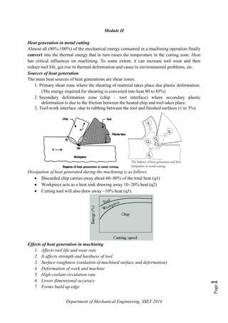
  • 1. Department of Mechanical Engineering, SSET 2014 Page1 Module II Heat generation in metal cutting Almost all (90%-100%) of the mechanical energy consumed in a machining operation finally convert into the thermal energy that in turn raises the temperature in the cutting zone. Heat has critical influences on machining. To some extent, it can increase tool wear and then reduce tool life, get rise to thermal deformation and cause to environmental problems, etc. Sources of heat generation The main heat sources of heat generations are shear zones. 1. Primary shear zone where the shearing of material takes place due plastic deformation. (The energy required for shearing is converted into heat 80 to 85%) 2. Secondary deformation zone (chip – tool interface) where secondary plastic deformation is due to the friction between the heated chip and tool takes place. 3. Tool-work interface -due to rubbing between the tool and finished surfaces (1 to 3%) Dissipation of heat generated during the machining is as follows  Discarded chip carries away about 60~80% of the total heat (q1)  Workpiece acts as a heat sink drawing away 10~20% heat (q2)  Cutting tool will also draw away ~10% heat (q3). Effects of heat generation in machining 1. Affects tool life and wear rate 2. It affects strength and hardness of tool 3. Surface roughness (oxidation of machined surface and deformation) 4. Deformation of work and machine 5. High coolant circulation rate 6. Lower dimensional accuracy 7. Forms build up edge
  • 2. Department of Mechanical Engineering, SSET 2014 Page2 Cutting temperature distribution Cutting temperature is not constant through the tool, chip and workpiece. It is observed, that the maximum temperature is developed not on the very cutting edge, but at the tool rake some distance away from the cutting edge. The temperature field in the cutting zones is shown in the figure. Factors influencing Cutting temperature 1. Work material a) Energy required (less energy means less temperature) b) Soft and Ductility-cutting temperature is high c) High thermal conductivity material reduces temperature 2. Tool geometry a) Increased Rake angle reduces the cutting temperature b) Increased cutting edge angle reduces the cutting temperature c) Increased nose radius reduces the temperature slightly 3. Cutting condition a. Cutting speed – most significant factor(Increases with speed) b. Feed has less influence on cutting temperature c. Depth of cut has least influence 4. Cutting fluid  Cutting fluid reduces the temperature (reduces the friction and carries away the heat) From this figure is obvious, that any reduction of the cutting temperature will require substantial reduction in either the cutting speed or cutting feed, or both (the effect of depth of cut can be neglected). But cutting time and therefore production rate will decrease. To avoid the problem, application of cutting fluid (coolants) is the solution.
  • 3. Department of Mechanical Engineering SSET 2015 Page3 Tool temperature measurement The power consumed in metal cutting is converted into heat. The magnitude of the cutting temperature need to be known or evaluated to facilitate 1. Assessment of machinability (judged by cutting forces, temperature and tool life) 2. Design and selection of cutting tools 3. Proper selection and application of cutting fluid 4. Analysis of temperature distribution in the chip, tool and job 5. Evaluate the role of variation of the different machining parameters on cutting temperature The temperatures which are of major interests are: etemperaturcuttingAverage etemperaturerfacechiptoolAverage etemperaturzoneshearAverage avg i s : int: : :    Cutting temperature can be determined by two ways: 1. Analytically – using mathematical models (equations). This method is simple, quick and inexpensive but less accurate and precise. 2. Experimentally – this method is more accurate, precise and reliable The feasible experimental methods are: 1. Decolourising method – some paint or tape is pasted on the tool or job near the cutting point and change in colour with variation of temperature may also often indicate cutting temperature 2. Tool-work thermocouple – simple and inexpensive but gives only average 3. Photo-cell technique 4. Infra rad detection method Brief description of few methods (Experimental) Tool-work thermocouple In a thermocouple two dissimilar but electrically conductive metals are connected at two junctions at different temperature. The difference in temperature at the hot and cold junctions produce a proportional current which is detected and measured by a milli- voltmeter (mV). In machining, the tool and the job constitute the two dissimilar metals and the cutting zone functions as the hot junction.
  • 4. Department of Mechanical Engineering SSET 2015 Page4 Photo cell technique This technique enables accurate measurement of the temperature along the shear zone and tool flank. The electrical resistance of the cell, like PbS cell, changes when it is exposed to any heat radiation. Holes are drilled at places where temperature is to be measured. The cell receiving radiation through the small hole and change in resistance of photo cell is measured which depends upon the temperature of the heat radiating source. Infra red pyrometer method Each body with a temperature above the absolute zero emits an electromagnetic radiation from its surface, which is proportional to its intrinsic temperature. By knowing the amount of infrared energy emitted by the object and its emissivity, the object's temperature can often be determined. The basic design consists of a lens to focus the infrared (IR) energy on to a detector, which converts to an electrical signal that can be displayed in units of temperature Tool material With the progress of the industrial world it has been needed to continuously develop and improve the cutting tool materials and geometry 1. To meet the growing demands of high productivity, quality and economy of machining 2. To enable effective and efficient machining of the exotic materials that are coming up with the rapid and vast progress of science and technology 3. For precision and ultra-precision machining (micro and nano level machining) Reasons for development of new tool material
  • 5. Department of Mechanical Engineering SSET 2015 Page5 Properties of Cutting Tool Materials The cutting tool material should possess the following properties 1. Hot hardness It is the ability of the tool material to retain its hardness and cutting edge at elevated temperatures. Hot hardness can be increased by adding cobalt, chromium molybdenum, tungsten and vanadium. 2. Wear Resistance It is the ability of the tool material to resist wear when operating at high speeds. The wear resistance can be increased by adding carbon and alloying elements. 3. Toughness It is ability to resist shock and vibrations without breaking. This is particularly important for interrupted cuts. 4. High thermal conductivity and specific heat To conduct the heat generated at the cutting edge. 5. Coefficient of friction The coefficient of friction between the chip and the tool should be as low as possible in the operating range of speed and feed. 6. Favorable cost, easy to fabricate and easy to grind and sharpen. 7. It should have low mechanical and chemical affinity for the work material. Selection of Cutting Tool Materials The selection of cutting tool material will depend on the following factors: 1. Volume of production demanded 2. Cutting condition 3. Type of machining process 4. Physical and chemical properties of materials 5. Rigidity of the machine. Classification of Tool Materials 1. High Carbon Steel 2. High Speed Steel 3. Stellite (Cast-Cobalt alloys) 4. Cemented Carbide 5. Coated Carbides 6. Ceramics 7. Cermet 8. CBN 9. Diamond 10. PCD
  • 6. Department of Mechanical Engineering SSET 2015 Page6 Carbon Steel Carbon steel, also called plain carbon steel, is a metal alloy, a combination of two main elements, iron and carbon plus small amounts of manganese, phosphorus, sulfur, silicon to improve the properties. These steels usually with less than 1.5 percent carbon and generally categorized according to their carbon content. Generally, with an increase in the carbon content from 0.01 to 1.5% in the alloy, its strength and hardness increases but causes appreciable reduction in the ductility and malleability of the steel. Plain carbon steels are further subdivided into groups: 1. Low Carbon Steels/Mild Steels contain up to 0.3% carbon 2. Medium Carbon Steels contain 0.3 – 0.6% carbon 3. High Carbon Steels contain more than 0.6% to 1.5% carbon High carbon: It is very hard, wear resistant and difficult to weld. Used for cutting tools Typical Composition carbon steel: Carbon - 0.8 to 1.3% Silicon - 0.1 to 0.4 % Manganese 0.1 to 0.4 %
  • 7. Department of Mechanical Engineering SSET 2015 Page7 General Characteristics/properties/advantages of high carbon steel 1. Suitable for low cutting speeds, limited to about 10 m/min using coolant supply. 2. Low hot hardness (Used where cutting temperature is below 200°C). Hardness lost at 350°C). 3. Have good hardness and toughness (when heated and tempered). 4. Easy to forge and simple to harden. 5. Low cost 6. Can undergo heat treatment Limitations of plain carbon steel 1. Plain-carbon steels have poor corrosion resistance 2. Plain-carbon steel oxidises readily at elevated temperatures. 3. There cannot be strengthening beyond a limit without significant loss in toughness and ductility. Application Used to make reamers, hacksaw blades, taps and dies etc High Speed Steels The term `high speed steel' was derived from the fact that it is capable of cutting metal at a much higher rate than carbon tool steel and continues to cut and retain its hardness even when the point of the tool is heated to a low red temperature. The alloying elements increase the strength, toughness, wear resistance and cutting ability. The basic composition of HSS 18% W 4% Cr 1% V 0.7% C and rest is Fe Properties /features 1. HSS can operate at cutting speeds 2 to 3 times higher that of high carbon steel. Cutting speed up to 30 m/min 2. Excellent toughness- It takes shocks and vibration during cutting 3. It retains hardness at elevated temperatures in the range of 550°C to 600°C. 4. Higher metal removal rates. 5. Less Costly Application 1. Used to make lathe tools, drills, reamers, shaper tools, slotting tools, farming equipments and compression springs etc. Coated HSS A very thin coating of 5-7µm thickness of wear resistant material on conventional HSS tool is provided to improve its performance. Vapor chemical deposition technique is used to give the thin coatings of titanium or zirconium carbide and nitrides on HSS tools.
  • 8. Department of Mechanical Engineering SSET 2015 Page8 Stellite Composition 48-53% 30-33% 10-20% 1.5-2.0% Co Cr W C  Manufacturing Process- Casting  Hot hardness- 760ºC  Cutting Speed -45 m/min  Higher tool life compare to H.S.S.  Lower toughness/brittle Cemented Carbides The Cemented Carbides are a range of composite materials, which consist of hard carbide particles bonded or cemented together by a metallic binder. Pure tungsten carbide powder and carbon is mixed and then mixed with binder at high temperature and manufactured by powder metallurgy methods. Its unique combination of strength, hardness and toughness satisfies the most demanding applications. It is usually used as tool inserts brazed on to steel holders. Example of tool: Tungsten carbide, titanium carbide etc Composition of tungsten carbide tool W C Co 94% 6% cobalt (Binder) Properties 1. High hardness and wear resistance 2. Maximum limiting cutting temperature -1200 ºC 3. Cutting Speed -100 m/min so High material removal rate 4. High Tool life 5. Gives better surface finish 6. Easy to manufacture with powder metallurgy methods (low cost) Application  Used in machining tough materials such as carbon steel or stainless steel, as well as in situations where other tools would wear away, such as high-quantity production runs. Coated tungsten carbide Thin film of coating of hard and wear resistive materials like Titanium Nitride (TiN), Titanium Carbide (TiC) and Aluminium Oxide (Al2O3) etc is deposited on surface to improve the life and service quality of tool. Chemical Vapor Deposition (CVD) or Physical Vapor Deposition (PVD) technique is used for coating deposition. Properties 1. High hot hardness-retains cutting edge sharpness at high temperature 2. High cutting speed -150 to 250 m/min 3. High Tool life (2 to 3 times higher than carbide) 4. Reduction of cutting forces and power consumption 5. Improvement in product quality - Chemically more stable
  • 9. Department of Mechanical Engineering SSET 2015 Page9 Applications: 1. Widely used for high speed machining 2. Machining of very hard materials Ceramics or Oxide tool Ceramic tool materials consist primarily of fine grained aluminium oxide, cold-pressed into insert shapes and sintered under high pressure and temperature. 1. They are hard, retain their hardness at high temperatures of 1700°C. 2. High Cutting Speed -200 to 400 m/min (Used for high speed machining ) 3. Good surface finish and dimensional accuracy in machining steels. 4. They have longer tool life 5. Chemically more stable (less tendency to adhere to metals during machining so low build up edge) Limitation: 1. Poor Toughness: They are extremely brittle and can’t take shock and vibrations (not suitable for interrupted cut) 2. Unreliable (sudden fail) and also high rigidity set up is required Application Used for cutting carbon steel and HSS Cermets A cermet is a composite material composed of ceramic and metallic materials. As the name suggests, cermets (derived from ceramics and metals) combine the positive properties of two material groups. Cermet is a cutting tool material composed mainly of TiC (Titanium Carbide) and TiN (Titanium Nitride) bonded together with a nickel (metal) binder. The objective to combine the properties of ceramics, such as 1. Hardness 2. Resistance to oxidation 3. Heat resistance 1. Toughness properties of metals, 2. Impact strength in order to create an ideal cutting material, “cermet” Properties (Properties comes between carbide and ceramics tool) 1. High hardness and more chemically stable, hence more wear resistant 2. High hot hardness greater than carbide tool and less than ceramics tool 3. High thermal shock resistance 4. Excellent surface finish at very high cutting speed 5. High tool life Application: Used for cutting steel and cast iron at high cutting speed.
  • 10. Department of Mechanical Engineering SSET 2015 Page10 Sialon Sialons are ceramics based on the elements silicon (Si), aluminium (Al), oxygen (O) and nitrogen (N. They are formed when silicon nitride (Si3N4), aluminium oxide (Al2O3) and aluminium nitride (AlN) are reacted together. The materials combine over a wide compositional range. Sialon ceramics are a specialist class of high-temperature refractory materials, 1. High strength, 2. Good thermal shock resistance and 3. Exceptional resistance to wetting or corrosion. 4. Oxidation resistance CBN: cubic born nitride CBN tools are very effective at machining most steels and cast irons, but they are also very expensive. It is the second hardest material known (second to diamond). CBN is used mainly as coating material because it is very brittle. Boron nitride has the formula (BN)n, (n is a very large number, but the empirical formula is BN). In the cubic form of boron nitride, alternately linked boron and nitrogen atoms form a tetrahedral bond network, exactly like carbon atoms do in diamond. Properties 1. CBN is an excellent abrasive resistance to cut 2. Very hard and high hot hardness -. can efficiently machine steel 3. Long Tool Life: provide uniform hardness and abrasion resistance in all directions. 4. High Material-Removal Rates: 700 -800 m/min 5. Lower cutting cost Application 1. Used for roughing and finishing operations 2. Machining of hard steel 3. High speed finish machining of hardened steel and super alloys Diamond Diamond has most of the properties (hardest) desirable in a cutting tool material. Diamond also has high strength, good wear resistance and low friction coefficient. Diamond is composed of pure carbon atoms, arranged in a very special crystal orientation that gives it its unique physical properties. Single crystal diamond tools have been mainly replaced by polycrystalline diamond (PCD). This consists of very small synthetic crystals fused by a high temperature high pressure process to a thickness of between 0.5 and 1mm and bonded to a carbide substrate. 1. It is the hardest cutting material. 2. It has low coefficient of friction, high compressive strength and extremely wear resistant. 3. Used for machining very hard material such as glass, plastics, ceramics etc.
  • 11. Department of Mechanical Engineering SSET 2015 Page11 4. It produces very good surface finish at high speeds with good dimensional accuracy. Best suited for light cuts and finishing operations. 5. It can resist upto a temperature of 1250°C. 6. High cutting speed (300 to 1000 m/min) Diamond coated tool The tool life of cemented carbide cutting tools is greatly improved by diamond coating, and typically more than 10 times the tool life is obtained. Diamond films are usually deposited more than 10 pm thick to make tool life longer, since tool life is directly related to film thickness. Coats tools with polycrystalline diamond, applied with a CVD process. The diamond coating can withstand the abrasiveness of these materials. High cutting speed, accuracy of cut and dry cut is possible. Comparison of diamond and CBN Diamond and CBN have the same crystal structure, with diamond consisting of pure carbon, whilst CBN is made up of the elements boron and nitrogen. In contrast to Diamond, CBN has no carbon atoms, making it suitable for machining steel. CBN is better suited for machining the following materials:  Hardened steel over approx. 54 HRc hardness and High-speed steel  Stellite and Nickel-based special alloys Diamond is generally used for machining non ferrous materials. Steel has a high affinity to carbon. Since Diamond consists of pure carbon, it is not suitable for machining steel. Indexable inserts A tipped tool generally refers to any cutting tool where the cutting edge consists of a separate piece of material, either brazed, welded or clamped on to a separate body. The advantage of tipped tools is only a small insert of the cutting material is needed to provide the cutting ability. Advantages of tipped tool 1. Small size insert makes manufacturing easier 2. Reduces cost because the tool holder can be made of a less-expensive and tougher material. 3. Easy to handle The indexable insert technique, meaning a replaceable cutting edge, or so called insert, was placed in the toolholder. Inserts are removable cutting tips, which means they are not brazed or welded to the tool body. This saves time in manufacturing by allowing fresh cutting edges to be presented periodically without the need for tool grinding and setup changes.
  • 12. Department of Mechanical Engineering SSET 2015 Page12 Tool failure Cutting tools generally fail by: 1. Gradual wear of the cutting tool at its flanks and rake surface. 2. Mechanical breakage and chipping due to excessive forces and shocks. 3. Plastic deformation of cutting edge due to intensive stresses and temperature. The last two modes of tool failure are very harmful and need to be prevented by using suitable tool materials and geometry depending upon the work material and cutting condition. But failure by gradual wear, which is inevitable, cannot be prevented but can be slowed down only to enhance the service life of the tool. It is considered that the tool has failed or about to fail by one or more of the following conditions: 1. Total breakage of the tool or tool tip(s) 2. Massive fracture at the cutting edge(s) 3. Excessive increase in cutting forces or vibration 4. Average wear (flank or crater) reaches its specified limit(s) 5. Excessive vibration and or abnormal sound (chatter) 6. Dimensional deviation beyond tolerance 7. Rapid worsening of surface finish Tool wears mechanism / mode of wear For the purpose of controlling tool wear one must understand the various mechanisms of wear that the cutting tool undergoes under different conditions. The common mechanisms of cutting tool wear are: 1) Mechanical wear a. abrasion, b. adhesion, c. chipping d. fatigue 2) Thermo-chemical wear a. diffusion wear 3) Chemical wear a. corrosion b. oxidation Abrasive wear: wear due to the abrasive action between the chip and tool as the chip passes over the rake surface of tool.
  • 13. Department of Mechanical Engineering SSET 2015 Page13 Adhesive wear: the tool and the chip weld together at contacts, and wear occurs by the fracture of these welded junctions. Welding is due to  Friction  High temperature  Pressure Fatigue wear: Due to friction while cutting, compressive force will be produced in one side and tensile force on other side. This causes the crack formation on the surface of tool and fails. Chipping of tool: It refers the breaking away of small chips from the cutting edge of tool Diffusion wear: When a metal is in sliding contact with another metal the temperature at the interface is high. The high temperature allows the atoms of hard material to diffuse into softer material matrix. At high temperature there is an intimate contact between the chip and the tool rake face. Atoms of the softer metal may also diffuse into harder medium, thus weakening the surface of harder material. Diffusion phenomenon is strongly dependent on temperature Oxidation wear: Oxidation wear is the result of reaction between tool face material and oxygen present in the vicinity. Corrosion wear: may be included in wear phenomenon Gradual or progressive tool wear / (types of wear) a) Flank wear b) Crater wear c) Nose wear d) Plastic deformation of tools The main wears in cutting tool are 1) Crater wear –occurs on top rake face due to diffusion and friction between tool and chip. Crater wear dominates at high speeds. 2) Flank wear –occurs on flank (side of tool) due to abrasive rubbing between the tool flank and the newly generated work surface. Flank wear dominates at low speed 3) Nose wear is the rounding of a sharp tool due to mechanical and thermal effects
  • 14. Department of Mechanical Engineering SSET 2015 Page14 The tool wear depends on a number of factors such as: 1. Hardness and type of tool material. 2. Cutting tool geometry. 3. Feed and depth of cut. 4. Cutting fluid. 5. Material and condition of work-piece. 6. Dimensions of the work-piece. Effects of tool wear Tool wear causes the tool to lose its original shape and lose its cutting efficiency. Tool wear is a time dependent process. As cutting proceeds, the amount of tool wear increases gradually. But tool wear must not be allowed to go beyond a certain limit in order to avoid tool failure. 1. Increase the cutting force 2. Increase the surface roughness 3. Decreases dimensional accuracy 4. Increase the cutting temperature 5. Creates vibration 6. Reduce the quality of work 7. Increase the cost and lower the cutting efficiency
  • 15. Department of Mechanical Engineering SSET 2015 Page15 Tool wear criteria/tool life criteria In practical situation, the time at which a tool ceases to produce work-pieces with desired size, surface quality and acceptable dimensional tolerances, usually determines the end of tool life. In most cases the tool wears gradually and the roughness of the machined surface becomes too high, cutting forces rise and cause intolerable deflections or vibrations etc. As the tool wear rate increases, the dimensional tolerances can not be maintained. When the wear reaches a certain size, it will accelerate and may lead to a sudden failure of the edge. In economical machining under normal cutting condition, wear on the flank is usually the controlling factor. So flank wear is the criteria (ISO test) normally used to assess the tool life. Some wear is inevitable. (flank wear is normally the most consistent form of wear which is easy measurable). It is measured by the width of flank wear (VB/FW shown in figure) is used to define the tool life. If the amount of flank wear exceeds some critical value (VB -0.3 to 0.5mm) the excessive cutting force may cause tool failure. Other failure criteria based on crater wear, notch wear, surface finish and dimensional variations also used to define the tool life. When the cutting edge of the tool reaches one of the tool life criterion, the tool should be replaced by a new one or sending it for regrinding. Stages of tool wear Rapid initial wear as the new tool is introduced on to the work. Then wear rate reduces and takes a uniform rate and finally wear exceeds a limit it gets failed The width of flank wear land is usually taken as a measure of the amount of wear land deciding the wear allowable before regrinding or disposal of tool (measured using tool maker’s microscope).  Region AB- rapid wear rate due the initial broken down of cutting edge  Region BC- uniform wear rate  Region CD- increasing rate
  • 16. Department of Mechanical Engineering SSET 2015 Page16 Tool Life A tool cannot cut for an unlimited period of time. After using for a certain period of time, it ceases to cut satisfactorily unless it is re-sharpened. It has a definite life. The tool life maybe defined as the time elapsed (actual cutting time) between two consecutive sharpening of the cutting tool. The tool life can be measured in the following ways: 1. Volume of material removed between two successive grindings. 2. Number of pieces machined between two successive grindings. 3. Total time of operation. 4. Equivalent cutting speed. Factors affecting Tool Life (same factors of machinability) 1. Tool and Work Material 2. Tool Geometry 3. Cutting Speed 4. Feed and Depth of Cut 5. Cutting Fluid 6. Rigidity of tool, work and machine. 7. Area of cut Tool Life Equation (Taylor’s Equation based on Flank Wear) Tool life of any tool for any work material is governed mainly by the level of the machining parameters i.e., cutting velocity (VC), feed (f) and depth of cut (t1). Usually flank wear (VB) is taken as the criteria for fixing the wear limit for tool change and its dependence on cutting velocity are schematically shown below:  The tool life obviously decreases with the increase in cutting velocity keeping other conditions kept constant.  Life of the tools T1, T2, T3, and T4 are plotted against the corresponding cutting velocities V1, V2, V3, and V4, a smooth curve like a rectangular hyperbola is found.  By plotting VC and T and the log scale the following plot was obtained.
  • 17. Department of Mechanical Engineering SSET 2015 Page17 Taylor derived the tool life equation, VTn = C or V1T1 n = V2T2 n =C Where, T = tool life in minutes V = cutting speed in m/min n = index which depends on tool and work-piece = 0.1 to 0.5 for HSS tools = 0.2 to 0.4 for carbide tools = 0.4 to 0.6 for ceramic tools C = constant. It is numerically equals to cutting speed that gives a tool life of one minute. The value of C depends on tool-work material and cutting environment (feed and depth of cut). 2211 loglogloglog TnVTnV  12 21 loglog loglog TT VV n    Note: If the higher cutting speed is permitted by a tool for the same life, we can say that the tool is having better cutting properties and it will be more productive.
  • 18. Department of Mechanical Engineering SSET 2015 Page18 Effect of tool life on rake, clearance angle, cutting time and temperature  Tool life increases with increase of rake angle for the given cutting speed. Increase of rake angle decreases the cutting force and temperature.  As the clearance angle increases, the tool chip contact area increases which reduces the cutting temperature and wear rate ultimately increases the tool life.  Increases of nose radius also increases the life to a extent  Wear increases with cutting temperature. All types of wear accelerate with increase of temperature (mechanical, chemical and diffusion wear)  Cutting time- tool wear is a time dependent factor. As cutting proceeds, the amount of tool wear increases gradually. There is optimum value of rake and clearance angle which gives maximum tool life
  • 19. Department of Mechanical Engineering SSET 2015 Page19 Machineability It can be defined as the ease with which a material can be machined by a given tool under a given set of conditions. Suppose it is states as material A is more machinable than material B, then it means that: 1. Tool wear rate is less when machining material A 2. Better surface finish is obtained for material A. 3. Less power is consumed during the machining of material A. Factors affecting machinability 1. Work variables a) Chemical composition of the workpiece material. b) Microstructure of the workpiece material. c) Mechanical properties like ductility, brittleness, toughness etc. d) Physical properties of the work material. e) Method of production of the work material. 2. Tool variables a) Geometry of the tool. b) Tool material c) Rigidity of the tool. d) Nature of engagement of the tool with the work. 3. Machine variables a) Rigidity of the machine b) Power and accuracy of the machine tool. 4. Cutting conditions a) Cutting speed b) Feed c) depth of cut d) cutting fluid Evaluation or assessment of Machinability (Criteria for evaluating machinability) 1. Tool life for a given cutting speed and tool geometry. 2. Material Removal Rate. 3. Magnitude of cutting forces and power requirement. 4. Quality of the surface finish of the work material. 5. Accuracy of dimensions of the workpiece. 6. Ease of chip disposal 7. Shape and size of chips formed. 8. Heat generated during the cutting process. 9. Power consumption per unit volume of material removed.
  • 20. Department of Mechanical Engineering SSET 2015 Page20 Advantages of high machinability 1. Good surface finish can be obtained. 2. Higher cutting speed can be employed. 3. High Material Removal Rate 4. Less tool wear. 5. Less power consumption. Machiability Index It is a quantitative measure of machinability. It is used to compare the machinability of different metals. The machinability index of free cutting steel is arbitrarily fixed as 100%. Thus for other metals machinability index is given by: lifetooluteforsteeldardsofspeedCutting lifetooluteformaterialofspeedCutting IIndexityMachinabil min20tan min20 ,  Methods to improve the machinability The machinability of the work materials can be improved, by the following ways:  Favourable change in composition, microstructure and mechanical properties by mixing additive(s) in the work material and appropriate heat treatment  Proper selection and use of cutting tool material and geometry depending upon the work material and the significant machinability criteria under consideration  Optimum selection of cutting parameters  Proper selection and appropriate method of application of cutting fluid depending upon the tool – work materials  Proper selection of special techniques like hot, cryogenic machining etc,  By changing the method of work material production, eg: cold worked material shows higher machinability Machinability of Titanium, Aluminium and Copper alloys Materials with good machinability require little power to cut, can be cut quickly, easily obtain a good finish, and do not wear the tooling much. Titanium The machinability of titanium and its alloys is generally considered to be poor owing to several inherent properties of the materials. The machinability index of titanium is about 30% or less (0.3). Machininability involves careful selection of tool geometry and speed. Poor machinability may due following properties  Titanium is very chemically reactive  Tendency to weld to the cutting tool during machining, thus leading to chipping  Its low thermal conductivity increases the temperature which affects the tool life and build up edge
  • 21. Department of Mechanical Engineering SSET 2015 Page21 Aluminum alloys Compared to other construction materials, aluminium is easy to machine and gives good tool life. Carbide tool gives 600m/min cutting speed.  In general, the specific cutting force for aluminium is about 30% that of steel.  Most aluminum alloys are easily machined and yields greater tool life and productivity.  Machinability index of aluminium is about 300 to 1500% (Excellent machinability)  Aluminium is machined using tools made of tool steel, high-speed steel, cemented carbides and diamond Although readily machinable, aluminum has a high coefficient of friction and high thermal coefficient of expansion. This means a special approach is required including the use of polished tools with different tool geometry and good lubrication to avoid thermal stress. Chips are of the continuous type. The primary tooling concerns when machining aluminum are: minimizing the tendency of aluminum to stick (BUE) to the tool cutting edges and poor surface finish Copper alloys All coppers and copper alloys can be machined accurately, cheaply and to a good standard of tolerances and surface finish. Machining copper alloys is considerably easier than machining steels of the same strength.  Significantly lower cutting forces  The machinability rating of this alloy is 1.6 to 2 (160 to 200%)  Brass is more easy to machine than bronze Tools used for machining  Usually tungsten carbide-cobalt, coated HSS, CBN or PCD cutting tools are used. Effect s of cold working on machinability Cold working of work materials results in many improvements on its properties resulted in better machinability. A cold worked material gives following characteristics. 1. Improved surface finish 2. Controlled dimensional tolerance and concentricity 3. Improve machinability Economics of Metal Cutting The primary aim is to produce satisfactory parts at the lowest possible cost and highest possible production rate. As the cutting speed increases the MRR is high giving low cutting cost, but the tool life will be shorter and consequently high cutting cost per piece. At some intermediate cutting speed, the tool cost will be minimum. The tool life corresponding to this speed is economical tool life. The total cost per piece is based on:  Non productive cost
  • 22. Department of Mechanical Engineering SSET 2015 Page22  Cutting or machining cost  tool changing cost The machining cost per component is made up of a number of different costs. Non- productive cost per component includes the cost of loading and unloading component, and other non-cutting time costs. Select speed to achieve a balance between high metal removal rate and suitably long tool life . Mathematical formulas are available to determine optimal speed Two alternative objectives in these formulas: 1. Maximum production rate 2. Minimum unit cost Maximizing production rate = minimizing cutting time per unit Cutting force measurement The forces generated by a machining process can be monitored to detect a tool failure or to diagnose and controlling the process parameters, and in evaluating the quality of the surface produced. There are many force measurement systems, such as strain gages, inductive and capacitive systems. During machining, the cutting tool exerts a force on the work piece. The cutting force includes tangential, feed and radial force. These force components can be measured with a dynamometer. Quartz crystals experience the piezoelectric effect which produces electric charge when the material is deformed. The cutting force is measured either directly gauging the deformation caused or by sensing the deformation with a transducer or converting it.
  • 23. Department of Mechanical Engineering SSET 2015 Page23 Cutting Fluid During a metal cutting operation heat is generated due to plastic deformation of the metal and friction of the tool-work interface. The increase in temperature reduces the hardness of the tool. This leads to tool failure. Cooling the work prevents the excessive thermal distortion of the work and cooling the tool helps to increase tool life Cutting fluid is used to carry away the heat produced during the machining and reduce the friction between the chip and the tool. Cutting fluids in the form of a liquid are applied to the chip formation zone to improve the cutting conditions. If the tool has low value of hot-hardness, there is appreciable increase in tool life as result of cutting fluid supplied to the cutting zone. In the case of carbides and oxides which have high value of hot-hardness, cutting fluid has negligible effect on the tool life. Functions of the Cutting Fluid 1. To cool the tool and work during machining (dissipate heat) 2. To lubricate ( to reduce friction) a. It reduces the power consumption b. It prevents the formation of BUE c. Increases tool life d. Reduces heat generated at the tool chip interface 3. To protect the finished surface from corrosion. 4. To cause the chips break into small pieces. 5. Chips are disposed off easily 6. To improve surface finish Properties of Cutting Fluid 1. Good lubricating properties to reduce frictional and the power consumption. 2. High heat absorbing capacity (high specific heat) 3. It should high heat conductivity. 4. High flash point. 5. Should be non corrosive to work and tool. 6. It should have low viscosity to permit free flow of liquid. 7. Should not lose its properties when exposed to heat. 8. It should not react with the work piece 9. Should be economical in use. Types of cutting fluids a) Water based cutting fluid b) Straight cutting oils c) Synthetic cutting fluid (from chemicals) Water based Cutting Fluids To improve the cooling and lubricating properties of water, the soft soap and mineral oils are added to it. Soluble oils are emulsions composed of around 80% of water, remaining soap and mineral oils. The soap acts as the emulsifying agent which breaks the oil into particles to minute particles to disperse them throughout water.
  • 24. Department of Mechanical Engineering SSET 2015 Page24 It has got excellent cooling properties at low cost and has got some lubricating effect between the chip and the tool. By varying the proportion of water cutting fluids with wide range of cooling and lubricating properties are obtained. Water bases cutting fluids may be adopted for medium and high speed applications. This is due to the fact that at low speeds the heat transfer characteristics may be low but lubricity should be high. At high speeds good heat transfer characteristics are more desirable. Straight or oil Based cutting fluids Straight or oil based cutting fluids means undiluted or pure oil based fluids. These oils have good lubricating properties but poor heat absorption quality. The heat transfer rates by their application are the lowest among cutting fluids. Thus they are only suitable for low cutting speeds. Used for heavy cutting process like broaching, threading and gear etc. Poor cooling and smoke formation are the disadvantages They can be classified into the following groups: 1. Mineral oils 2. Fatty oils 3. Combination and mineral and fatty oils Oil with additives a) The beneficial effect of mineral oils can be improved with the help of additives, which are generally compounds of sulphur and chlorine. b) Other additives may also be used to improve stability and anti rust properties. Selection of Cutting Fluids : The guidelines for selection of cutting fluids are: a) Type of machining process b) Based on tool and work materials c) Based on cutting condition like speed, feed etc d) Method of application of fluid e) Temperature involved Methods of application a) Flooding – cutting fluid is flooded over the cutting area b) Jet – cutting fluid under pressure with nozzle c) Mist – mixed with compressed air Oil with extreme pressure characteristics may be adopted for low speed cuts. Example: Machining of aluminium using water based cutting fluid Alloy steel uses water based and mineral oil etc Cast iron – dry machining (no cutting fluid is needed as free graphite in cast iron) ************************************************
  • 25. Department of Mechanical Engineering SSET 2015 Page25 Problems Example 1: A lathe running at a speed of 4000 rev./min is cutting Mild Steel with a H.S.S. tool. The spindle speed is reduced to 3000 rev./min. calculate the percentage change in tool life Given, V1 = Initial cutting speed. V2 = Reduced cutting speed. T1 = Tool life at V1. T2 = Tool life at V2. Take, n = 0.125 VTn = C VT0.125 = C So T1 0.125 = ( C / V1 ) And T2 0.125 = ( C / V2 ) (T1/T2)0.125 = (C/V2) (C/V1) (T2/T1)0.125 = C x V1 V2 x C (T2/T1)0.125 = V1 V2 (T2/T1) = 9.99 T2 = 9.99xT1 This shows that reducing cutting speed by 25% increases tool life by nearly 10 times (under the cutting conditions of this particular setup). Problem 2: In the previous example, for instance, if it were to be observed that the initial tool life (T1) was 4 hours and cutting speed 30m/min., then: - VTn = C 30 x (4x60(mins))0.125 C = 59.5
  • 26. Department of Mechanical Engineering SSET 2015 Page26 Problem 3 If the value of n for mild steel workpiece material and carbide tool material is 0.1 then at the same cutting speed of 30 m/min: VTn = C 30 x T0.1 = 59.5 T0.1 = 59.5 30 T = 941 minutes As opposed to 240 minutes using the H.S.S. tool. Problem 4 If in turning of a steel rod by a given cutting tool (material and geometry) at a given machining condition ( feed f and depth of cut t1) under a given environment (cutting fluid application), the tool life decreases from 80 min to 20 min. due to increase in cutting velocity, VC from 60 m/min to 120 m/min., then at what cutting velocity the life of that tool under the same condition and environment will be 40 min.?
  • 27. Department of Mechanical Engineering SSET 2015 Page27 Problem 5 During a tool life-cutting test on HSS tool material, following data were recorded. Calculate the values of n and C of taylor’s equation
  • 28. Department of Mechanical Engineering SSET 2015 Page28
  • 29. Department of Mechanical Engineering SSET 2015 Page29 Module II Question 1. Define machinability.**** 2. Define machinability index.**** 3. What do you mean by machinability ? Explain the method of determining machinability of a material and the factors affecting machinability.***** 4. Define machinability. How it is expressed? State the factors affecting the machinability of material.****** 5. Explain the term machining economics and machiuability index. 6. The machinahility index of SS and of Al alloys is 30 and 1500 respectively. What does it signify 7. Discuss the functions effecting machinability. 8. What is the effect of cold working in machinability? ***************************************************************** 9. What the properties are of required for a tool material? Give the details of some common tool materials. 10. Present the developments in cutting tool materials in the last decade 11. What are the desirable characteristics of cutting tool materials? Describe how they are satisfied in High Speed Steel tools. ** 12. Discuss the factors affecting tool life and discuss requirements of tool material to get reasonable tool life. 13. Discuss briefly various cutting tool materials. 14. Explain any two cutting tool material characteristics. 15. What is HSS and what are its advantages '? 16. When do you use the diamond as cutting tool material? 17. What are the factors affecting tool life and how it is improved? *** 18. Define tool life and state the factors- affecting tool life. ***` 19. Define tool life and explain how it is accessed in metal cutting operations. 20. Explain the relationship between tool life and cutting speed.** 21. What is Taylor tool life equation? Explain economic cutting speed.** 22. Define tool life. Derive Taylor's relationship for cutting speed-tool life.** 23. What is the effect of cutting speed on tool life 24. Classify the different types of tool life tests 25. Discuss the significance of too life. 26. Discuss economic tool life. 27. A 25 mm. dia steel bar was turned at 3000 r:p.m. using HSS tool. Tool failure occurred after 10 minutes. When the speed was reduced to 250 r.p.rn., the tool failed in 52.5 minutes. Assuming Taylor equation is valid, find the expected tool life at a speed of 275 rpm. 28. For a HSS tool cutting mild steel at 20 m./min, the life is 4 hours. Calculate its life when the cutting speed is increased to 24 m./min: 29. What is the tool life of a HSS tool 10-15-6-6-18-14-2 working at 50 m/min?
  • 30. Department of Mechanical Engineering SSET 2015 Page30 30. What are the factors influencing tool wear? Explain how the process parameters can be controlled to reduce wear and improve life. 31. Explain the mechanism of tool wear. How can it be measured?** 32. State the reasons responsible for tool failure.** 33. Name the different types of tool wear and explain. briefly about use of chip breakers 34. Discuss the various modes of tool wear. 35. Describe different types of tool wear. How is tool wear assessed? 36. What are the classifications of tool wear? Describe them.**** 37. Why is flank wear used as the criterion of tool life studies? 38. What are the common mechanisms causing wear on cutting tools? Explain.*** 39. Give the composition, properties and applications of any four cutting tool materials. 40. Name the techniques used for measuring tool wear. Described their advantages and limitations. 41. Explain flank wear. 42. What do you mean by crater wear" and Flank wear? How are they measured? 43. What are "Cermets”? How are they manufactured? 44. Explain the effect of cutting speed, feed and depth of cut on tool life. 45. What determines how wider a wear land can be allowed before the tool should be resharpened? ******************************************************************* 46. What are the functions of cutting fluids? **** 47. What are the essential properties of a cutting fluid `?*** 48. List out the purpose and properties of cutting fluids.** 49. What are the classifications of cutting fluids?** 50. Give an account of different types of cutting fluids and their use. 51. Explain the following types of cutting fluid a. Water based cutting fluids. b. Straight or seat oil based cutting fluid 52. Briefly explain the theory of cutting fluid with a diagram. 53. How are cutting fluids selected '? 54. How you will select the cutting fluids for machining? (4 marks) 55. What are the two types of cutting fluids? What are thin major applications? 56. Can cutting fluids have any adverse effects? If so, what are they? 57. Explain the reasons for selecting water based cutting fluids? ************************************************************ 58. What are the sources of heat generation in metal cutting? ****************************************************** 59. Explain the computation of Cost components" and-"Total production cost" of a machined 60. Discuss the economics of metal cutting. 61. What are the different cost components in Total production cost”?
  • 31. Department of Mechanical Engineering SSET 2015 Page31 62. Describe the relationships among cutting speed, rate of production and production cost? 63. Discuss the effect of friction during cutting. How can the friction be reduced? *************************************** Question before 2003 64. Why is pore size important in the manufacture of self lubricating bearing? How may pore size be controlled Ans: Sintering of powder compacts does not generally produce full density products (density between 0.9 to 0.98 theoretical density). PM bearings are self-lubricating because their porosity is impregnated with lubricants during the manufacturing process. In use, heat causes the lubricant to expand out of the pores forming a film between mating parts. When operation is suspended, the lubricant cools and is drawn back into the pores for subsequent reuse. These voids take up to10% to 35% of the total volume. In operation, lubricating oil is stored in these voids and feeds through the interconnected pores to the bearing surface. Any oil which is forced from the loaded zone of the bearing is reabsorbed by capillary action. Since these bearings can operate for long periods of time without additional supply of lubricant, they can be used in inaccessible or inconvenient places where relubrication would be difficult. High porosity with a maximum amount of lubricating oil is used for high-speed light-load applications Pore size is depend on size and shape of metal powder and compacting pressure, sintering temperature, sintering time etc **********************************************************************
  • 32. Department of Mechanical Engineering SSET 2015 Page32 General Extra notes Modified Taylor’s Tool Life Equation In Taylor’s Equation only the cutting velocity is considered, but practically, the variation in feed f, and depth of cut t1, plays an important role in the tool life. The modified Taylor Equation is given by, T = C . VC x x fy x t1 z Where, T = tool life in min, C = constant depending on tool and workpiece x,y,z = exponents so called tool life exponents depending upon the tool, work material and cutting conditions. Crater Wear The wear that occurs on the tool face in the form of a depression is known as crater, which begins at a certain distance from the cutting edge. The crater is restricted to the tool chip contact area. The crater is formed some distance away from the cutting edge and is maximum when the chip tool interface temperature is maximum. The formation of crater is due to adhesion, diffusion etc. and is a time dependant phenomenon. Effect of various tool wear factors Cutting speed Higher cutting speed increases tool temperature and softens the tool material. It thereby aids abrasive, adhesion and diffusion wear. The tool life is given by Taylor’s equation. Feed The larger the feed, the greater is the cutting force per unit area of the chip-tool contact on the rake surface and work-tool contact on the flank surface. The cutting temperature increases and different types of wear increases. An increase in cutting force as a result of larger feed also increases the likelihood of chipping of the cutting edge through material shock.The effect of changes in feed on tool life is relatively smaller that of proportionate changes in cutting speed.
  • 33. Department of Mechanical Engineering SSET 2015 Page33 Depth of Cut If the depth of cut is increased, the area of the chip-tool contact increases roughly in equal proportions to the change in depth of cut. Consequently the rise in temperature is relatively small. But when comparing with feed the change in temperature is larger. This is due to the fact that the area of chip-tool contact in increased depth of cut changes by a small proportion, than that of change in feed rate. Cutting Fluid The cutting fluid cools the chip and the workpiece and reduces the frictional stress at the tool-work interface and the chip-tool interface. Thus the cutting forces are reduced and thus the cutting temperature. In the case of carbides and oxides which have high value of hot-hardness, cutting fluid has negligible effect on the tool life. Rigidity of Tool, work piece and machine If the machine is not properly designed, if the workpiece is long and thin or if the tool hang is excessive, chatter may occur during cutting. Chatter may cause fatigue failure or catastrophic failure of the tool due to mechanical shock. Measurement of tool wear: The various methods are a) by loss of tool material in volume or weight, in one life time – this method is crude and is generally applicable for critical tools like grinding wheels. b) by grooving and indentation method – in this approximate method wear depth is measured indirectly by the difference in length of the groove or the indentation outside and inside the worn area using optical microscope fitted with micrometer – very common and effective method c) using scanning electron microscope (SEM) – used generally, for detailed study; both qualitative and quantitative The wears were measured by scanning electron microscope and the cutting forces measured by a dynamometer. There is clear relationship between flank wear and cutting forces. Lower cutting forces leads to low flank wear and low cutting force provides good dimensional accuracy of the work material including low surface roughness. Flank wear formation was mostly caused by abrasion and less by adhesion. Tool Life Measurement in terms of Metal Removal The volume of metal removal between tool sharpening for definite depth of cut, feed and cutting speed can be determined as follows: Cutting speed V = π D N / 1000 (for turning) Where, D = diameter of workpiece (mm) N = RPM of workpiece Let, t1 = depth of cut in mm f = feed mm/min TF = time of tool failure in min
  • 34. Department of Mechanical Engineering SSET 2015 Page34 Volume of metal removed per revolution = π D t1 f mm3 Volume of metal removed per minute = π D t1 f N mm3 Volume of metal removed in TF minute = π D t1 f N TF mm3 Tool Life, L = π D t1 f N TF mm3 = 1000 V t1 f TF mm3 Effects of alloying elements on tool steel properties:  Carbon: Raising carbon content increases hardness slightly and wear resistance considerably. Dramatic increases to hardness & strength when heat treated.  Manganese: Small amounts of of Manganense reduce brittleness and improve forgeability. Larger amounts of manganese improve hardenability, permit oil quenching (less severe queching required - which reduces quenching deformation).  Silicon: Improves strength, toughness, and shock resistance.  Tungsten: Improves "hot hardness" - used in high-speed tool steel.  Vanadium: Refines carbide structure and improves forgeability, also improving hardness and wear resistance.  Molybdenum: Improves deep hardening, toughness, and in larger amounts, "hot hardness". Used in high speed tool steel because it's cheaper than tungsten.  Chromium: Improves hardenability, wear resistance and toughness.  Nickel: Improves toughness and wear resistance to a lesser degree. Structure of carbon steel  The addition of carbon to the pure iron results in a considerable difference in the structure.  Austenite This phase is only possible in carbon steel at high temperature. It has a Face Centre Cubic (F.C.C) atomic structure which can contain up to 2% carbon in solution.  Ferrite: This phase has a Body Centre Cubic structure (B.C.C) which can hold very little carbon; typically 0.0001% at room temperature.  Cementite: Unlike ferrite and austenite, cementite is a very hard intermetallic compound consisting of 6.7% carbon and the remainder iron.  Pearlite: A mixture of alternate strips of ferrite and cementite in a single grain. A fully pearlitic structure occurs at 0.8% Carbon.
  • 35. Department of Mechanical Engineering SSET 2015 Page35 Structure of high speed steel Aluminium Next to steel, Aluminum is the most commonly used and commercially available metal. Its light weight and high strength-to-weight ratio make it a good choice for everything from aircraft to flashlights. These are light weight having good malleability and formability, high corrosion resistance and high electrical and thermal conductivity. However, in the engineering application pure aluminum and its alloys still have some problems such as relatively low strength, unstable mechanical properties. The microstructure can be modified and mechanical properties can be improved by alloying, cold working and heat treatment. Titanium is one of the fastest growing materials used. Titanium and its alloys are used extensively in aerospace and other area like petroleum, chemical, marine nuclear fields because of their excellent combination of  High specific strength (strength-to-weight ratio) at elevated temperature,  High fracture resistant  High exceptional resistance to corrosion etc