Downloaded 178 times
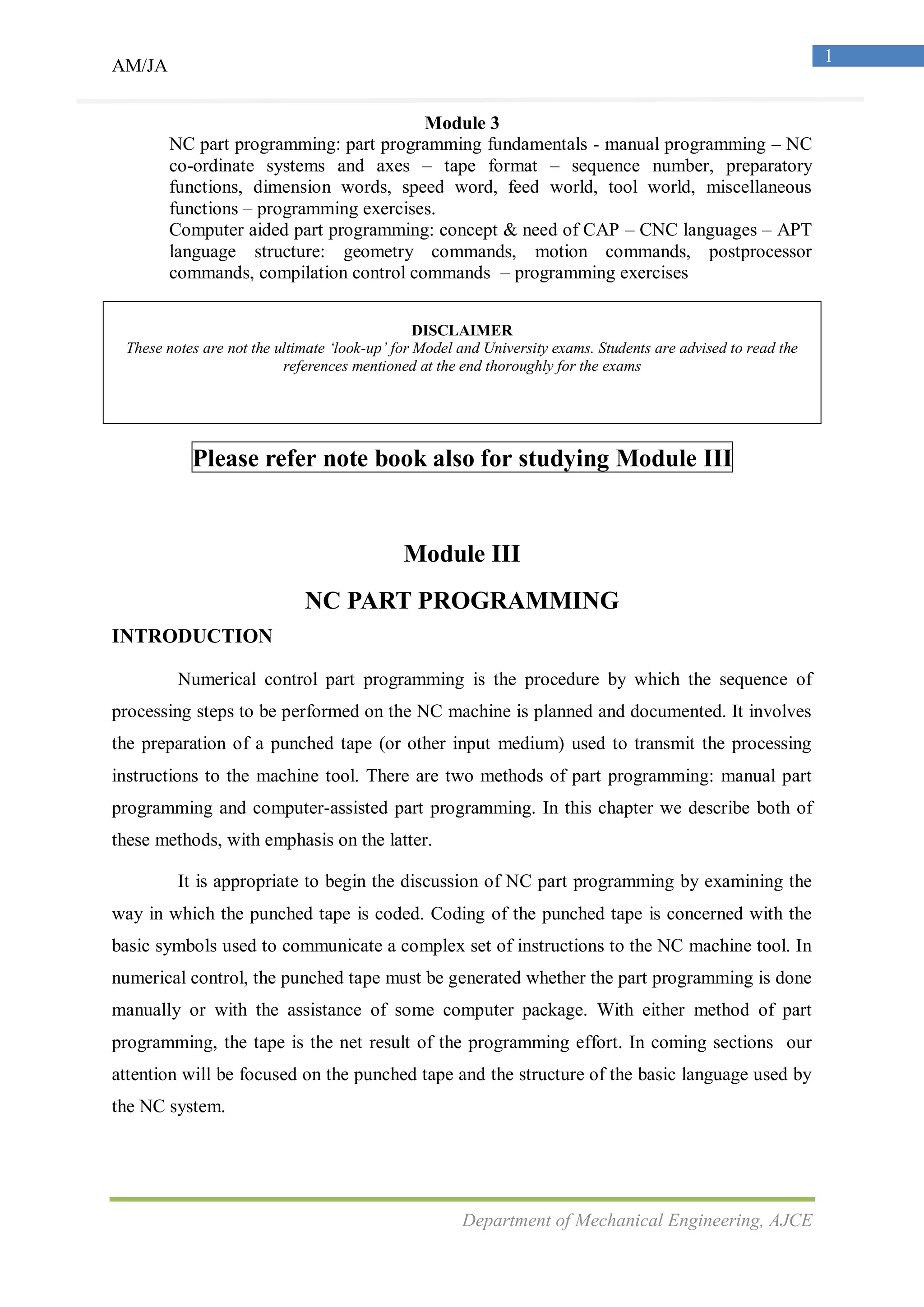
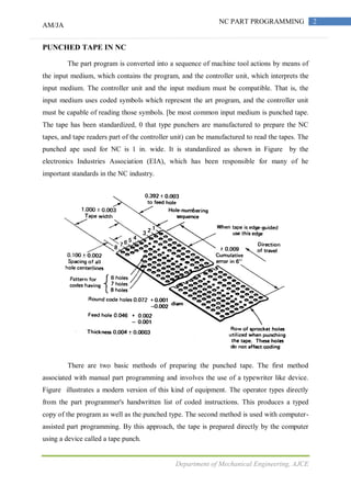
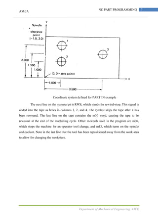
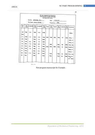
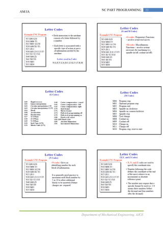
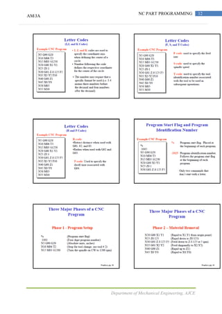
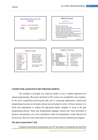
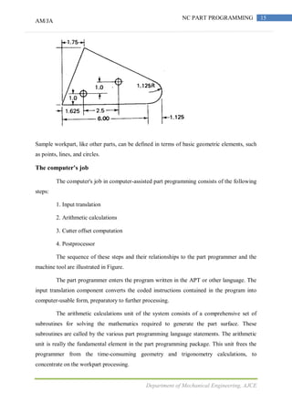


The document details the fundamentals of numerical control (NC) part programming, focusing on both manual and computer-assisted methods. It explains the coding and structure of punched tape, the main input medium for transmitting instructions to NC machines, including the basic symbols, functions, and organization of programming commands. The text emphasizes that while manual programming is suitable for simple jobs, computer-assisted programming is preferred for more complex tasks to improve efficiency and accuracy.


![Lecture 17 position systems of nc [compatibility mode]](https://cdn.slidesharecdn.com/ss_thumbnails/lecture17positionsystemsofnccompatibilitymode-140111213820-phpapp02-thumbnail.jpg?width=640&height=640&fit=bounds)