Downloaded 262 times
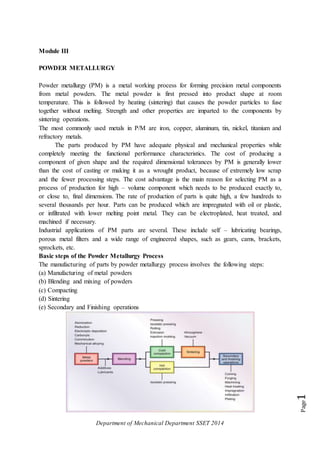


This document discusses powder metallurgy, which involves pressing metal powders into a shape at room temperature and then sintering the powders to fuse them together without melting. The most common metals used are iron, copper, aluminum, and others. Parts produced through powder metallurgy have good mechanical properties and dimensional tolerances at a lower cost than casting or machining. The document then describes various powder production methods like atomization, electrolysis, carbonyl decomposition, and comminution. It also discusses properties of metal powders like size, shape, purity and their effect on properties of sintered parts. The basic powder metallurgy process steps of blending, compacting, sintering and finishing