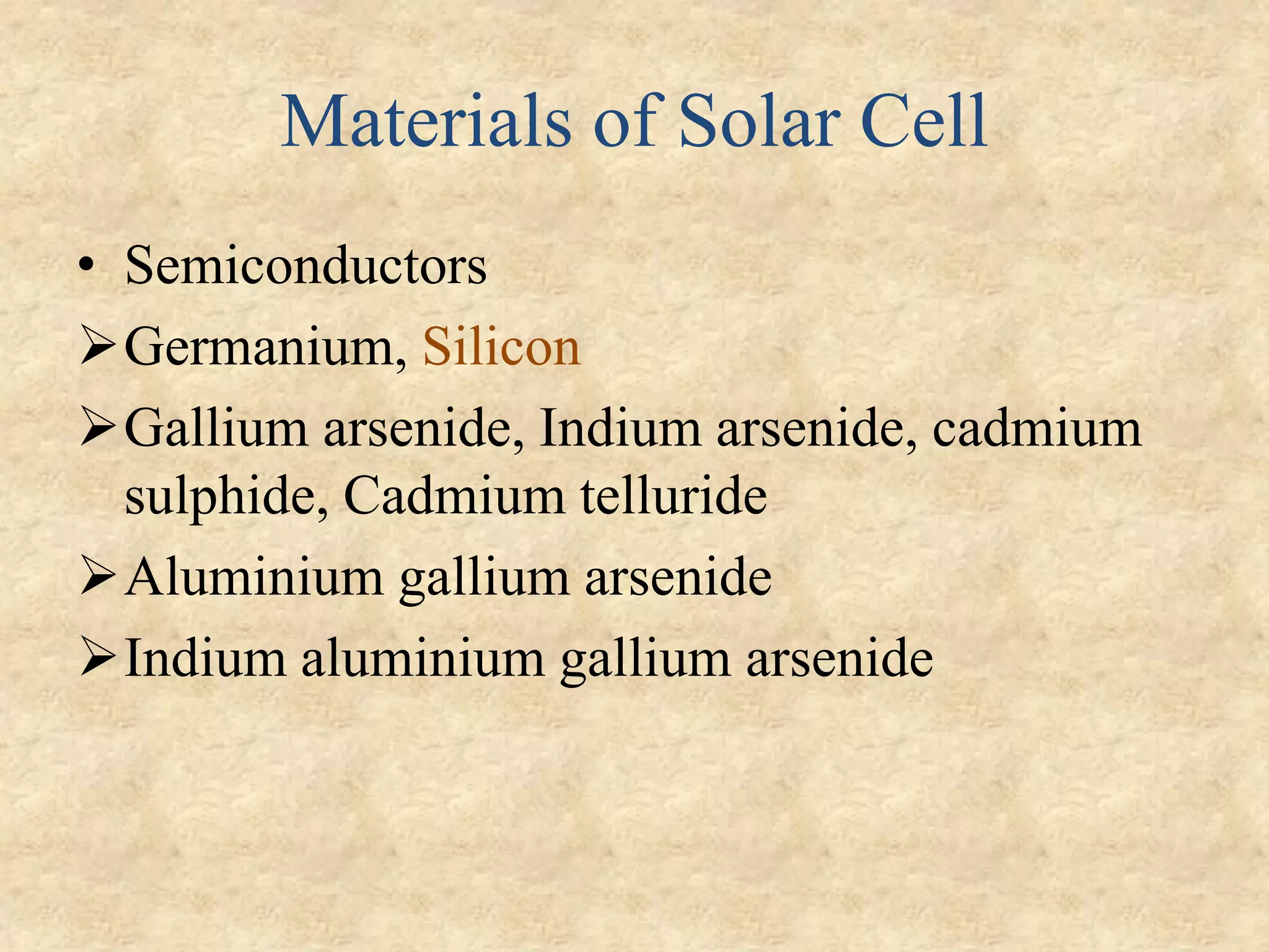
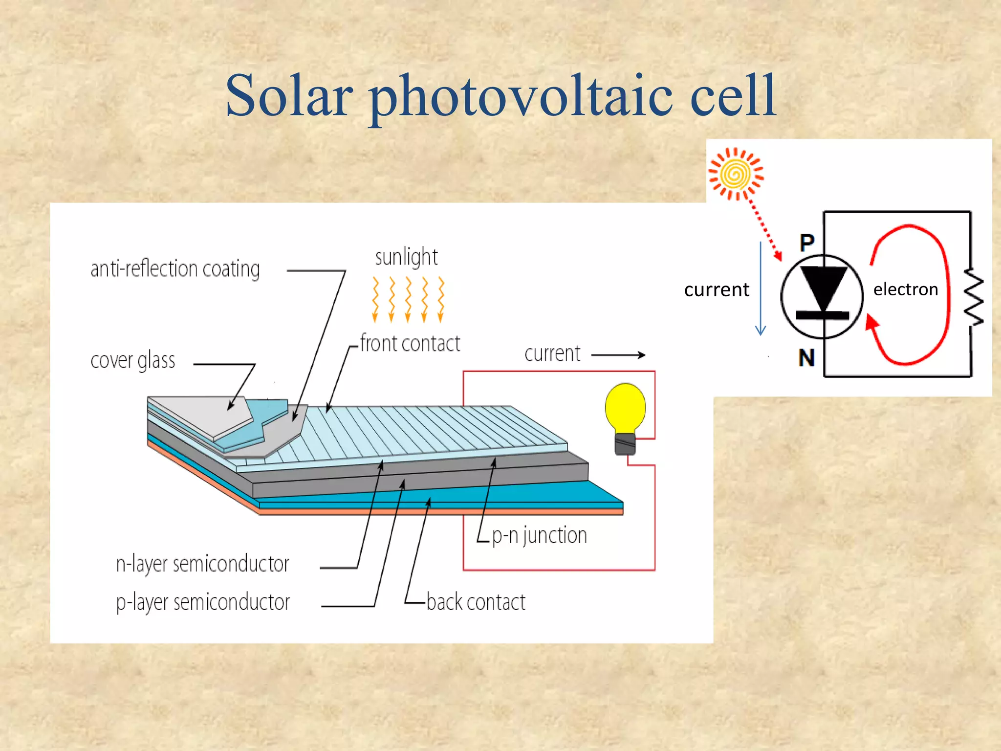
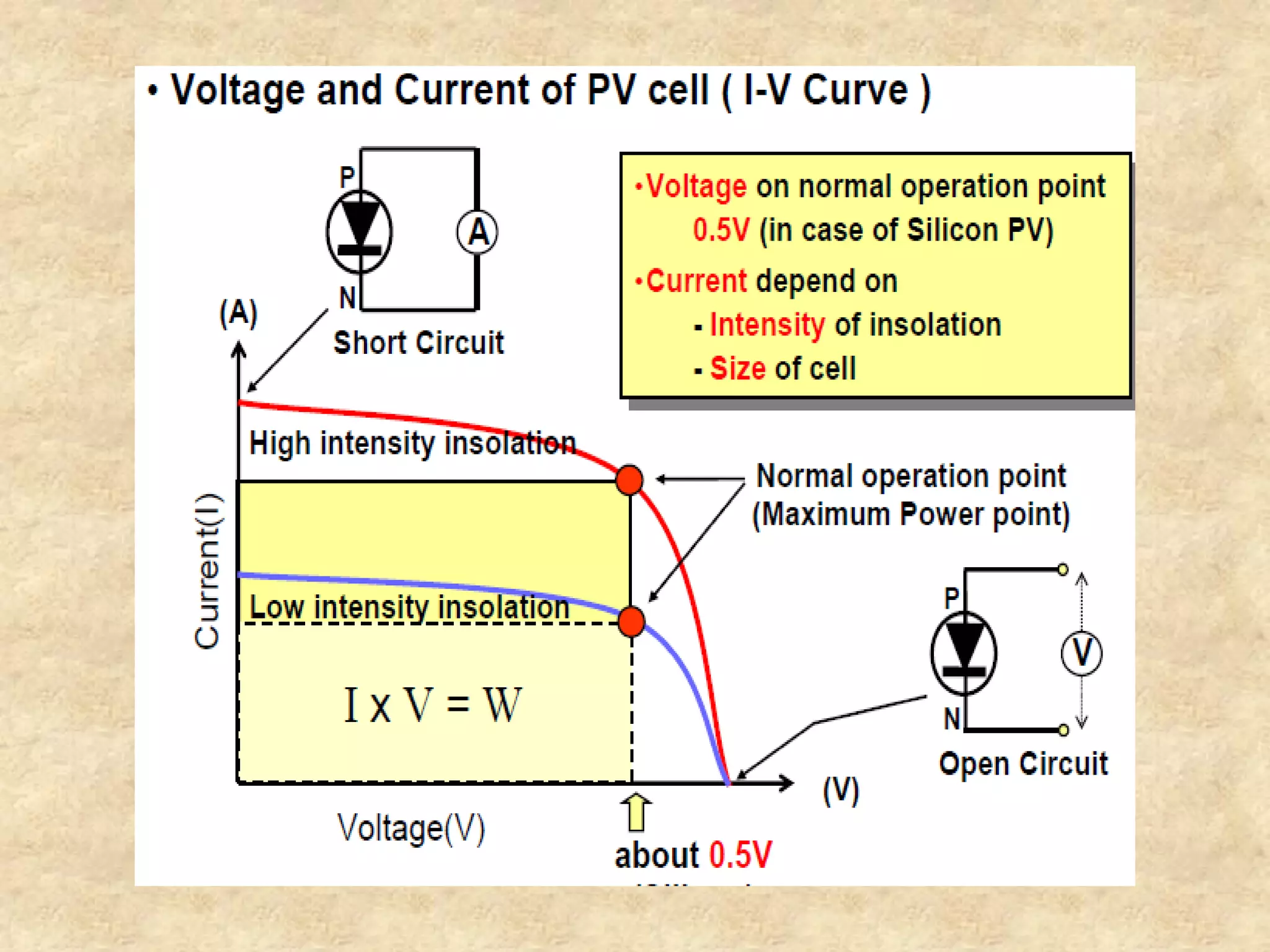
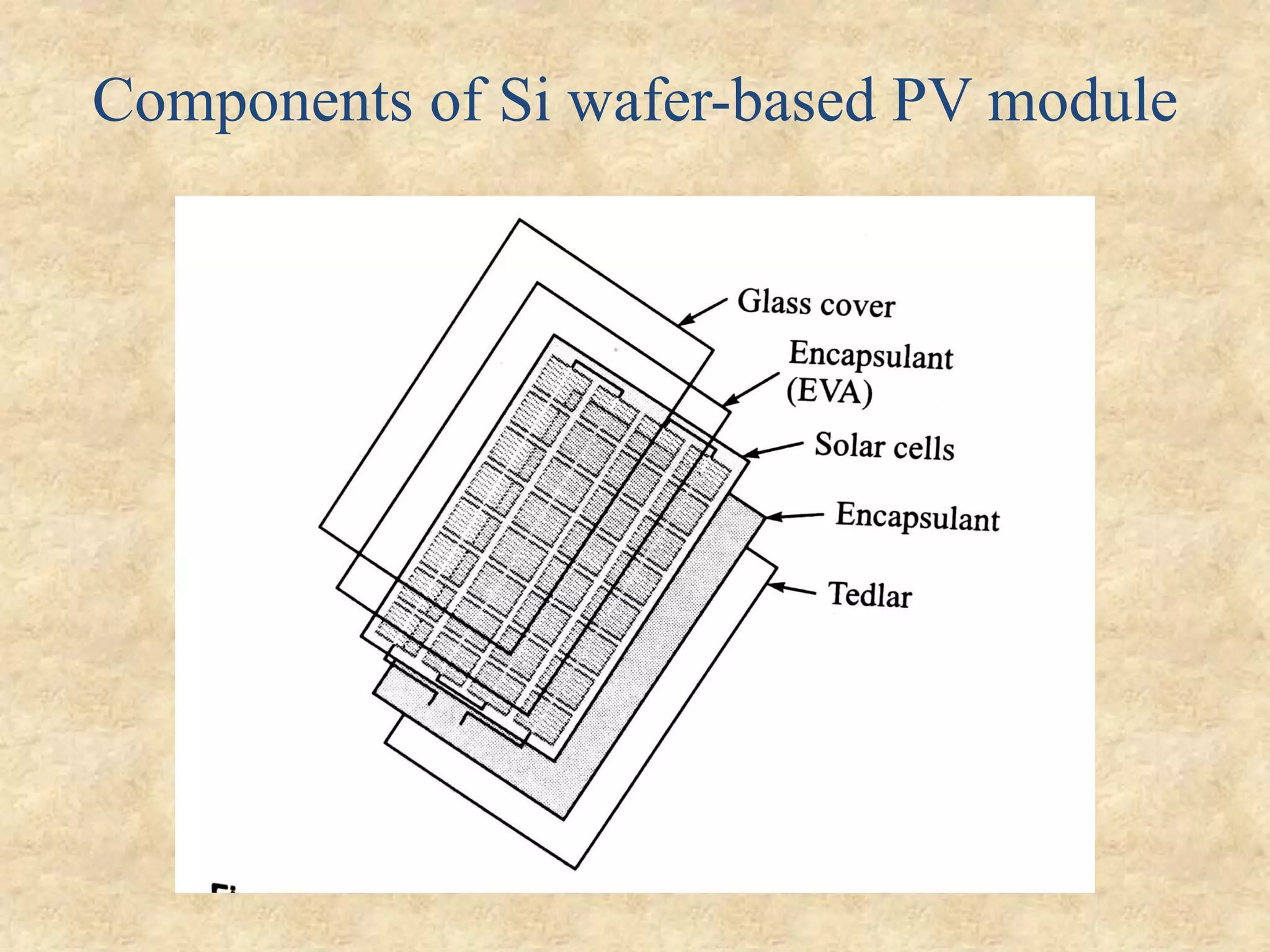
A photovoltaic cell, or solar cell, converts sunlight directly into electricity through the photovoltaic effect. Solar cells are made of semiconducting materials like silicon that produce electricity when struck by photons. In a solar cell, photons excite electrons in the material, allowing them to flow through an external circuit and produce a current. Solar cells are combined into solar panels or modules that provide higher voltages suitable for consumer applications. Proper sizing of solar PV systems involves determining power demands, sizing PV modules to meet those demands, selecting an appropriately sized inverter, and choosing battery capacity based on energy needs and days of autonomy required.
2. What is a Photovoltaic Cell?
• also called solar cell, is an electrical device that converts the
energy of light directly into electricity by the photovoltaic
effect.
Solar Cell (PV)
Light Electricity
3. Photovoltaic effect
• Sunlight is composed of photons, that contain various amounts
of energy corresponding to the different wavelengths of the solar
spectrum.
• The electrons present in the valence band absorb energy and,
being excited, jump to the conduction band and become free.
• These highly excited electrons are accelerated into a different
material by a built-in potential.
• This generates an electromotive
force(emf), and thus some of the
light energy is converted into electric
energy.
5. History of Solar Cells
Discovered by French physicist , Alexandre-Edmond Becquerel.
A description of the first solar cells made from selenium wafer
were made by Charles Fritts and operated at 1% effeciency .
Charles Fritts constructed what was probably the first true solar
cell. He coated a semiconductor material (selenium) with an
extremely thin layer of gold.
A cadmium sulphide p-n junction was produced with an
efficiency of 6%
Audobert and Stora discover the photovoltaic effect in
cadmium sulphide (CdS).
The Fraunhofer Institute for Solar Energy achieve a 44.7%
efficiency in solar cell technology.
The University of South Wales breaks the 20% efficiency barrier
for silicon solar cells under one sun conditions.
7. Solar cell – Working Principle
⚫ Operating diode in fourth quadrant generates power
8. • The solar cell is composed of a P-type semiconductor and an
N-type semiconductor.
• Solar light hitting the cell produces two types of charge carrier,
negatively charged electrons and positively charged holes in
the semiconductors.
• Negatively charged (-) electrons gather around the N-type
semiconductor while positively charged (+) holes gather
around the P-type semiconductor.
• .
9. • When sun light falls on silicon metal cell, the
photon energy allows the electrons from the P-
layer to move to the N-layer, creating an electric
potential difference on the semiconductor
borders.
• If these borders are connected to a load by
conductive wires, there will be a flow of electric
current, getting back the electrons to the P-layer
and starting the process again.
• A photovoltaic cell generally has low current
and voltage levels, of about 3 A and 0.7 V,
respectively.
10.
11. Types of PV cells
Silicon Crystalline Cells Thin Film Cells
made by using crystalline silicon
solar cells, developed from the
microelectronics technology
industry.
made by depositing one or
more thin layers (thin film) of
photovoltaic material on a
substrate.
Mono Crystalline PV Cells
Multi Crystalline PV Cells
Amorphous Silicon
PV Cells
Poly Crystalline PV
Cells
(Non-Silicon based)
12. Silicon Crystalline Technology
Currently makes up 86% of PV market
Very stable with module efficiencies 10-16%
Mono crystalline PV Cells
Made using saw-cut from single
cylindrical crystal of Si
Operating efficiency up to 15%
Multi Crystalline PV Cells
Caste from ingot of melted and
recrystallized silicon
Cell efficiency ~12%
Accounts for 90% of crystalline Si
market
13. Thin Film Technology
• Silicon deposited in a continuous on a base material such as
glass, metal or polymers.
• Thin-film crystalline solar cell consists of layers about 10μm
thick compared with 200-300μm layers for crystalline silicon
cells.
• Low cost substrate and
fabrication process.
• Not very stable .
14. Amorphous Silicon PV Cells
The most advanced of thin film technologies . Manufactured by
applying thin-layer manufacturing technology for
semiconductor
Operating efficiency ~6% .
Makes up about 13% of PV market .
• Mature manufacturing
technologies available
• Very flexible. Easy to fit on
any shape of substrate.
• Initial 20-40% loss in
efficiency .
Glass substrate type
Film substrate type
15.
16.
17. Solar PV Module
• Interconnected smaller solar cells
• Two ways
1 Thin film technology
2 Wafer based technology
• Solar cell 0.25𝑊𝑃 − 3.37𝑊𝑃
• Solar PV Module 3𝑊𝑃 − 300𝑊𝑃
(𝑊𝑃 =Pick power)
18.
19. Series and Parallel connection of cell
• Series connection for increase o/p voltage
• Parallel connection for increase o/p current
20.
21. Mismatch in Module
• Difference in the cell processing
• Same rating but different manufacturer
• Partial shading of cells or modules
• Damage caused by UV light on semi-
transparent cell
• Breaking of glass cover
22. Hot spots & Bypass diode in PV
Module
• Under series short circuit condition of the
string cell will become reverse biased.
• Due to cell breakdown lot of heat generate and
generate extra power Hot spot
• Bypass diode is used to avoid the destructive
effect of hot spots or local heating.
• In parallel connection blocking diodes use for
avoid hot spots.
25. PV systems
• Three categories
1. Stand-alone PV systems
2. Grid-connected PV systems
3. Hybrid PV systems
26. Stand-Alone PV system Dependence
• Load requirements
• Resource availability
• Performance of the system
• Reliability of the system
• Cost of the system
27. Type of load in stand-alone PV system
➢Type-a Unregulated with DC load
Load varies according sunshine condition
No arrangement for energy storage
28. Type-b Regulated with DC Load
• For power regulator maximum power point
tracker(MPPT) circuit inserted.
• MPPT circuit gives smooth operation
29. Type-c Regulated with Battery and
DC Load
• Used when non-sunshine hour or night-time operation
• Use charge controller circuit to prevent the
overcharging and deep discharging
33. Major system components
1) PV Module : converts sunlight into DC electricity.
2) Solar charge controller : Regulates the voltage and
current coming from the PV panels going to battery and
prevents battery overcharging and prolongs the battery life.
3) Inverter : Convert DC into AC
4) Auxiliary energy sources : diesel generator or other
renewable energy sources.
5) Battery
6) Loads
34. Solar PV system Sizing
1.Determine power consumption demands: Find out the total power
and energy consumption of all loads.
1.1 Calculate total Watt-hours per day for each appliance
used and add all.
1.2 Calculate total Watt-hours per day needed from the PV
module by multiplying by 1.3 because of system losses.
2. Size the PV modules : To find out the sizing of PV module, the
total peak watt produced needs. The peak watt (Wp) produced
depends on size of the PV module and climate of site location.
We have to consider “panel generation factor”. For India
PGF is 4.32.
35. 2.1 Calculate the total Watt-peak rating needed for PV modules
by dividing total watt hour per day by PGF.
2.2 Calculate the number of PV panels for the system by dividing
total watt peak power by rated out put of solar module.
3. Invertor capacity : the inverter must be large enough to handle the
total amount of Watts you will be using at one time. The inverter size
should be 25-30% bigger than total Watts of appliances.
4. Battery capacity :
Total Watt-hours per day used by appliances x Days of autonomy
(0.85 x 0.6 x nominal battery voltage)
0.85 because of battery loss
0.6 depth of discharge
36. • Example: A house has the following electrical appliance usage:
• One 18 Watt fluorescent lamp with electronic ballast used 4 hours per day.
• One 60 Watt fan used for 2 hours per day.
• One 75 Watt refrigerator that runs 24 hours per day with compressor run 12
hours and off 12 hours.
• The system will be powered by 12 Vdc, 110 Wp PV module
1. Determine power consumption demands
Total appliance use = (18 W x 4 hours) + (60 W x 2 hours) + (75 W x 24 x 0.5 hours)
= 1,092 Wh/day
Total PV panels energy
needed
= 1,092 x 1.3
= 1,419.6 Wh/day.
37. 2. Size the PV panel
Actual requirement = 4 modules
So this system should be powered by at least 4 modules of 110 Wp PV
module.
3. Inverter sizing
Total Watt of all appliances = 18 + 60 + 75 = 153 W
For safety, the inverter should be considered 25-30% bigger size.
The inverter size should be about 190 W or greater.
2.1 Total Wp of PV panel
capacity
needed
= 1,419.6 / 3.4
= 413.9 Wp
2.2 Number of PV panels
needed
= 413.9 / 110
= 3.76 modules
38. • 4. Battery sizing
Total appliances use = (18 W x 4 hours) + (60 W x 2 hours) + (75 W x 12 hours)
Nominal battery voltage = 12 V
Days of autonomy = 3 days
Battery capacity = [(18 W x 4 hours) + (60 W x 2 hours) + (75 W x 12 hours)] x 3
(0.85 x 0.6 x 12)
Total Ampere-hours required 535.29 Ah
So the battery should be rated 12 V 600 Ah for 3 day autonomy.
References for solar sizing :
http://www.leonics.com/support/article2_12j/articles2_12j_en.php
http://www.firstgreen.co/2014/08/solar-pv-system-sizing-step-by-step-
approach-to-design-a-roof-top-system-and-software-analysis/