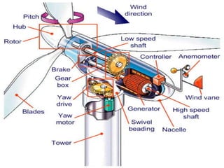
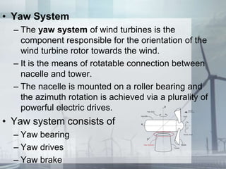
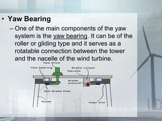
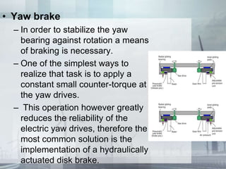
HORIZONTAL
AXIS WIND
TURBINE
(HAWT)
BY
K SAMEER AHMED (10J41A0220)
MAIN COMPONENTS OF HAWT
ROTOR
Blades
Hub
NACELLE
Low speed shaft
Brake
Gear Box
High speed shaft
Generator
Controller
Anemometer & Wind vane
Yaw System
TOWER
ROTOR (BLADES & HUB)
• BLADE
– Main part which convert free flowing wind energy
to useful energy.
– Uses Lift & Drag principle as shown in the picture.
– Three blade rotor is best compared to two and
single blade turbines.
• HUB
– In simple designs, the blades are directly bolted to
the hub.
– In other more sophisticated designs, they are
bolted to the pitch mechanism, which adjusts
their angle of attack according to the wind speed.
– The hub is fixed to the rotor shaft which drives the
generator through a gearbox.
NACELLE
• Nacelle provides housing for
• Low speed shaft
• Brake
• Gear Box
• High speed shaft
• Generator
• Anemometer
• Wind vane
• LOW SPEED SHAFT
– The shaft from hub to the Gear box
– Speed is typically between 40rpm to
400rpm
– Generators typically rotate at 1200rpm to
1800rpm.
• GEAR BOX
•Gearbox increases the speed of
the shaft.
•Meets the requirement of the
generator.
• High Speed Shaft
– Gearbox is followed by the high speed
shaft
– Connects to generator
• Braking Mechanism
•A mechanical drum
brake or disk brake is used
to stop turbine in
emergency situation.
•This brake is also used to
hold the turbine at rest for
maintenance
• Generator
– Wind power Generator converts wind
energy(mechanical energy) to electrical energy.
– Typically wind turbines generate electricity
through asynchronous machines that are directly
connected with the electricity grid.
– The Generator is attached at one end to the wind
turbine, which provides the mechanical energy.
– At the other end, the generator is connected to the
electrical grid.
– The generator need to have a cooling system to
make sure there is no overheating.
• Controller
– The controller starts up the machine at
wind speeds of about 8 to 16 miles per
hour (mph) and shuts off the machine at
about 55 mph.
– Turbines do not operate at wind speeds
above about 55 mph because they might
be damaged by the high winds
– The controller gets wind speed data from
the anemometer and acts accordingly .
• Yaw System
– The yaw system of wind turbines is the
component responsible for the orientation of the
wind turbine rotor towards the wind.
– It is the means of rotatable connection between
nacelle and tower.
– The nacelle is mounted on a roller bearing and
the azimuth rotation is achieved via a plurality of
powerful electric drives.
• Yaw system consists of
– Yaw bearing
– Yaw drives
– Yaw brake
• Yaw Bearing
– One of the main components of the yaw
system is the yaw bearing. It can be of the
roller or gliding type and it serves as a
rotatable connection between the tower
and the nacelle of the wind turbine.
• Yaw drive
– The yaw drive is used to keep the rotor facing into
the wind as the wind direction changes.
– The yaw drives exist only on the active yaw
systems and are the means of active rotation of
the wind turbine nacelle.
– Each yaw drive consists of powerful electric
motor (usually AC) with its electric drive and a
large gearbox, which increases the torque.
• Yaw brake
– In order to stabilize the yaw
bearing against rotation a means
of braking is necessary.
– One of the simplest ways to
realize that task is to apply a
constant small counter-torque at
the yaw drives.
– This operation however greatly
reduces the reliability of the
electric yaw drives, therefore the
most common solution is the
implementation of a hydraulically
actuated disk brake.
• Tower
– Typically, 2 types of towers exist
• Floating towers and
• Land-based towers.
– Floating towers can be seen in
offshore wind farms where the
towers are float on water.
– Land-based Towers can be seen
in the Onshore wind farm where
the towers are situated on the
land.
• For HAWTs, tower heights approximately two to
three times the blade length have been found to
balance material costs of the tower against
better utilisation of the more expensive active
components.
• At the bottom level of the tower there will be
stepup transformers for the connection to the
Grid.
THANK YOU

Horizontal Axis Wind Turbine

  • 1.
  • 2.
    MAIN COMPONENTS OFHAWT ROTOR Blades Hub NACELLE Low speed shaft Brake Gear Box High speed shaft Generator Controller Anemometer & Wind vane Yaw System TOWER
  • 4.
    ROTOR (BLADES &HUB) • BLADE – Main part which convert free flowing wind energy to useful energy. – Uses Lift & Drag principle as shown in the picture. – Three blade rotor is best compared to two and single blade turbines.
  • 5.
    • HUB – Insimple designs, the blades are directly bolted to the hub. – In other more sophisticated designs, they are bolted to the pitch mechanism, which adjusts their angle of attack according to the wind speed. – The hub is fixed to the rotor shaft which drives the generator through a gearbox.
  • 6.
    NACELLE • Nacelle provideshousing for • Low speed shaft • Brake • Gear Box • High speed shaft • Generator • Anemometer • Wind vane
  • 7.
    • LOW SPEEDSHAFT – The shaft from hub to the Gear box – Speed is typically between 40rpm to 400rpm – Generators typically rotate at 1200rpm to 1800rpm. • GEAR BOX •Gearbox increases the speed of the shaft. •Meets the requirement of the generator.
  • 8.
    • High SpeedShaft – Gearbox is followed by the high speed shaft – Connects to generator • Braking Mechanism •A mechanical drum brake or disk brake is used to stop turbine in emergency situation. •This brake is also used to hold the turbine at rest for maintenance
  • 9.
    • Generator – Windpower Generator converts wind energy(mechanical energy) to electrical energy. – Typically wind turbines generate electricity through asynchronous machines that are directly connected with the electricity grid. – The Generator is attached at one end to the wind turbine, which provides the mechanical energy. – At the other end, the generator is connected to the electrical grid. – The generator need to have a cooling system to make sure there is no overheating.
  • 10.
    • Controller – Thecontroller starts up the machine at wind speeds of about 8 to 16 miles per hour (mph) and shuts off the machine at about 55 mph. – Turbines do not operate at wind speeds above about 55 mph because they might be damaged by the high winds – The controller gets wind speed data from the anemometer and acts accordingly .
  • 11.
    • Yaw System –The yaw system of wind turbines is the component responsible for the orientation of the wind turbine rotor towards the wind. – It is the means of rotatable connection between nacelle and tower. – The nacelle is mounted on a roller bearing and the azimuth rotation is achieved via a plurality of powerful electric drives. • Yaw system consists of – Yaw bearing – Yaw drives – Yaw brake
  • 12.
    • Yaw Bearing –One of the main components of the yaw system is the yaw bearing. It can be of the roller or gliding type and it serves as a rotatable connection between the tower and the nacelle of the wind turbine.
  • 13.
    • Yaw drive –The yaw drive is used to keep the rotor facing into the wind as the wind direction changes. – The yaw drives exist only on the active yaw systems and are the means of active rotation of the wind turbine nacelle. – Each yaw drive consists of powerful electric motor (usually AC) with its electric drive and a large gearbox, which increases the torque.
  • 14.
    • Yaw brake –In order to stabilize the yaw bearing against rotation a means of braking is necessary. – One of the simplest ways to realize that task is to apply a constant small counter-torque at the yaw drives. – This operation however greatly reduces the reliability of the electric yaw drives, therefore the most common solution is the implementation of a hydraulically actuated disk brake.
  • 15.
    • Tower – Typically,2 types of towers exist • Floating towers and • Land-based towers. – Floating towers can be seen in offshore wind farms where the towers are float on water. – Land-based Towers can be seen in the Onshore wind farm where the towers are situated on the land.
  • 16.
    • For HAWTs,tower heights approximately two to three times the blade length have been found to balance material costs of the tower against better utilisation of the more expensive active components. • At the bottom level of the tower there will be stepup transformers for the connection to the Grid.
  • 17.