PV SYSTEM, installation design and development.pptx
1.
Solar PV Systems-ShortCourse
Course Tutor: PASCHAL YOHANA
paschalmadirisha2525@gmail.com
Department of Electrical
DONBOSCO OYSTERBAY V.T.C
Dar es salaam-Tanzania,
2025
Modules
1. Introduction toSolar Energy
2. Solar Radiation & PV Fundamentals
3. Components of a Solar PV System
4. System Types and Design Principles
5. Installation & Wiring
6. Troubleshooting & Maintenance
7. Costing & Customer Service
8. Final Project & Evaluation
4.
Module 1: Introductionto Solar Energy
• Importance of renewable energy
• Solar energy basics
• Types of solar technology: PV & thermal
• Practical: Mini solar kit demo
5.
Electricity Review
Electricity generation.
Electricitycan not be mined from the ground
like coal.
So it is called a secondary source of energy,
meaning that it is derived from primary sources,
including coal, natural gas, nuclear fission
reactions, sunlight, wind, and hydropower.
6.
Types of electricity
StaticElectricity.
made by rubbing together two or more objects
and making friction
Current Electricity(dc or ac).
flow of electric charge across an electrical field.
7.
Common method ofproducing voltage/
electricity
friction, magnetism, chemicals, light, heat, and
pressure. Friction is the oldest method
1.Friction: Energy produced by rubbing two
material together.
2.Heat: Energy produced by heating the junction
where two unlike metals are joined.
8.
Common method ofproducing voltage/
electricity
3. Light: Energy produced by light being absorbed
by photoelectric cells, or solar power.
4. Chemical: Energy produced by chemical reaction
in a voltaic cell, such as an electric battery
5. Pressure: Energy produced by compressing or
decompressing specific crystals.
6. Magnetism: Energy produced in a conductor that
cuts or is cut by magnetic lines of force
9.
Energy in general
Energyis an important commodity in the modern
world. We use it everyday in many different ways.
Here are some examples:
– Transportation
– Entertainment
– Communication
– Personal Comfort
– Agriculture
– Manufacturing
10.
Components of anEnergy System
i. Methods to harness, collect or extract energy
ii. Energy Conversion
iii. Energy Storage
iv. Transportation of Energy
Engineers develop new energy systems to make
the overall process as efficient as possible. The
technology that will allows the greatest end usage
from the energy collected.
11.
Types of EnergySources
i. Renewable Energy Sources
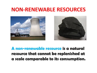
ii. Non-Renewable Energy Sources
12.
Renewable Energy Sources
i.Solar photovoltaics
ii. Solar thermal power
iii. Passive solar air and water heating
iv. Wind
v. Hydropower
vi. Biomass
vii. Ocean energy
viii.Geothermal
ix. Waste to Energy
What is renewableenergy?
Renewable energy: is generated from natural
resources that are inexhaustible and naturally
replenished (renewed) at a rate comparable to
its use
Advantages of RE
i.Big potential - the offer of renewable energies is
quantitatively nearly unlimited and could cover the
world's energy demand even if only a part of it is
used.
ii. High level of environmental friendliness (at least
compared to fissile and nuclear energy) -can reduce
the consumption of fossil fuels, thus reducing
pollution of the atmosphere.
iii. Good chances to supply even remote areas with
energy
iv. High degree of decentralization
17.
Disadvantages of RE
i.Lack of appropriate technology for all
renewable energies: Not for all kinds of
renewable energies have an appropriate
technology.
ii. Economically not reachable: High initial
costs / Not economically competitive.
iii. Supply of energy is not constant: for many
of the renewable energy sources
1. Introduction toSolar Energy
Importance of the sun
• Worshipping the sun in ancient times
i. Source of almost all renewable energies is sun.
ii. Solar energy can reduce the consumption of fossil fuels.
iii. Solar energy is unlimited and freely available.
iv. Fossil fuels limited and not evenly shared.
v. Energy crisis and increasing environmental pollution.
20.
Origin of SolarEnergy
• Belief that energy from sun is indefinite, Due to its
vast amounts compared to its use.
Diameter of sun 109 x bigger than earth’s.
Mass of sun 330,000 x bigger than earth’s.
Solar radiation: fusion reaction of hydrogen
21.
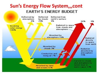
Sun’s Energy FlowSystem
Some 30% (5.25 x 10¹⁶W) of the incoming solar
radiation is directly reflected and scattered back
into space as short-ware radiation.
The earth’s atmosphere, the oceans and the land
masses absorb about 47% (8.17 x 10¹⁶
W)
These is converted directly into heat at the
ambient surface temperature and is re-radiated as
long wave radiation
Uses of DirectSolar Energy
i. Thermal use: Transform solar radiation into
heat energy
ii. Photovoltaic use: Solar radiation directly
transformed into electricity
24.
Solar Radiation Terminologies
1.Global radiation: whole radiation on the
earth's surface
i. Consists of direct sun radiation, diffuse
radiation of the sky and reflected radiation by
surrounding bodies
ii. Varies throughout the year
iii. Varies from region to region
iv. Varies during the day, at a particular location
25.
Terminologies – Cont…
2.Average daily global irradiation: total solar
energy received per day per m2
on horizontal
surface
• Sum of Direct Radiation + Diffuse Radiation +
Reflected Radiation
26.
a) Direct Radiation
Propagatesin straight line from sun
Casts shadows
Heavily depends on cloud cover
Varies from 0 to 90% of total radiation
Can be focused with lenses or mirrors
On sunny day most of radiation is direct
27.
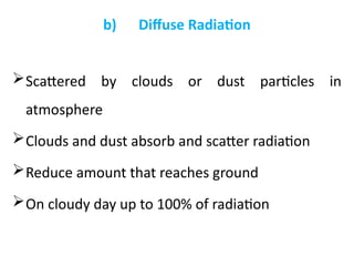
b) Diffuse Radiation
Scatteredby clouds or dust particles in
atmosphere
Clouds and dust absorb and scatter radiation
Reduce amount that reaches ground
On cloudy day up to 100% of radiation
28.
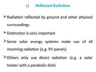
c) Reflected Radiation
Radiationreflected by ground and other physical
surroundings
Distinction is very important
Some solar energy systems make use of all
incoming radiation (e.g. PV panels)
Others only use direct radiation (e.g. a solar
heater with a parabolic dish)
29.
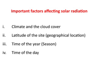
Important factors affectingsolar radiation
i. Climate and the cloud cover
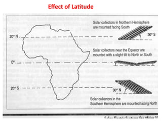
ii. Latitude of the site (geographical location)
iii. Time of the year (Season)
iv. Time of the day
1. Solar Irradiance
Isthe Solar radiation striking the surface, or the
power received per unit area from the sun
• Measured in watts or kilowatts per square metre.
(W/m2
) or (kW/m2
)
• Solar module facing the sun directly
(perpendicular to sun's rays), irradiance will be
much higher than if module is at a large angle to
the sun.
34.
Solar Irradiance –Ctd.
• In mornings and late afternoons, less power
received because flat surface is not at
optimum angle to the sun and because there
is less energy in solar beam.
• At noon, amount of power received is highest.
• Solar irradiance is expressed in W/m2
• Solar irradiance is measured by a device called
pyranometer or lux meter
35.
What is asolar cell?
• Solid state device that converts incident solar
energy directly into electrical energy
Efficiencies from a few percent up to 20-30%
No moving parts
No noise
Lifetimes of 20-30 years or more
36.
Semi-Conductor
• PV technologyuses semi-conductor materials to convert
photon energy to electron energy
• Many PV devices employ
i. Silicon (multi-crystalline, amorphous or single)
ii. Cadmium telluride, gallium arsenide, CIS, etc.
iii. Other electrically active semiconductor materials
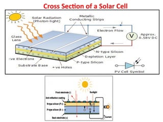
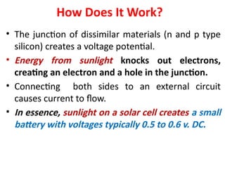
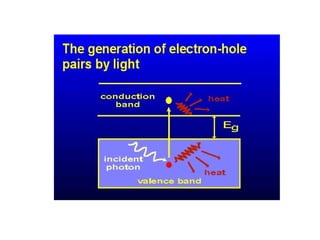
How Does ItWork?
• The junction of dissimilar materials (n and p type
silicon) creates a voltage potential.
• Energy from sunlight knocks out electrons,
creating an electron and a hole in the junction.
• Connecting both sides to an external circuit
causes current to flow.
• In essence, sunlight on a solar cell creates a small
battery with voltages typically 0.5 to 0.6 v. DC.
40.
Combining Solar Cells
•Solar cells can be electrically connected in
series (voltages add) or in parallel (currents
add) to give any desired voltage and current
(or power) output since P = I x V
• Photovoltaic cells are typically sold in
modules (or panels) of 12 volts with power
outputs of 5 to 100+ watts. These are then
combined into arrays to give the desired
power or watts.
41.
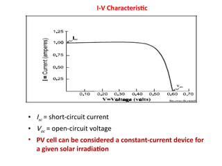
I-V Characteristic
• Isc= short-circuit current
• Voc = open-circuit voltage
• PV cell can be considered a constant-current device for
a given solar irradiation
42.
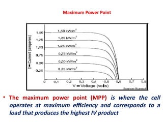
Maximum Power Point
•The maximum power point (MPP) is where the cell
operates at maximum efficiency and corresponds to a
load that produces the highest IV product
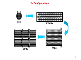
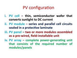
PV configuration
i. PVcell – thin, semiconductor wafer that
converts sunlight to DC current
ii. PV module – series and parallel cell circuits
sealed in a protective laminate
iii. PV panel – two or more modules assembled
as a pre-wired, field-installable unit
iv. PV array – complete power-generating unit
that consists of the required number of
modules/panels
45.
Types of PVmodules
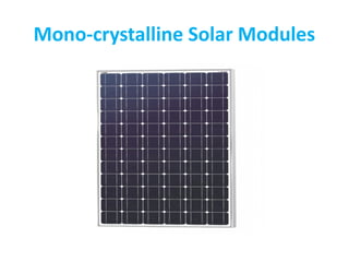
1. Mono-crystalline Solar Modules
It is a solar modules comprising mono-
crystalline solar cells.
When sunlight falls on the mono-crystalline
solar modules, the cells absorb the energy and
create an electric field through a complicated
process. Hence it comprises of voltage and
current which is directly used to run DC.
46.
Types of PVmodules
The panel cells have a pyramid pattern that offers a larger
surface area to collect more energy from the sun’s rays.
It reduces reflection and thereby increase absorption;
the cells are coated with silicon nitride.
These panels have life span up to 25-30 years.
metal conductors printed into cells.
Types of PVmodules
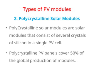
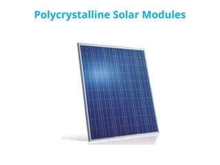
2. Polycrystalline Solar Modules
• PolyCrystalline solar modules are solar
modules that consist of several crystals
of silicon in a single PV cell.
• Polycrystalline PV panels cover 50% of
the global production of modules.
3. Thin-film SolarModules
It is a good option for projects with lesser
power requirements but needs for
lightweight and portability. Thin-film
technologies have produced a maximum
efficiency of 20.3%, with the most
common material amorphous silicon at
12.5%.
52.
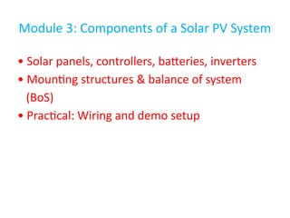
Module 3: Componentsof a Solar PV System
• Solar panels, controllers, batteries, inverters
• Mounting structures & balance of system
(BoS)
• Practical: Wiring and demo setup
53.
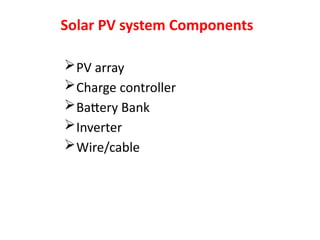
Solar PV systemComponents
PV array
Charge controller
Battery Bank
Inverter
Wire/cable
54.
54
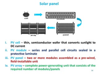
Solar panel
i. PVcell – thin, semiconductor wafer that converts sunlight to
DC current
ii. PV module – series and parallel cell circuits sealed in a
protective laminate
iii. PV panel – two or more modules assembled as a pre-wired,
field-installable unit
iv. PV array – complete power-generating unit that consists of the
required number of modules/panels
55.
55
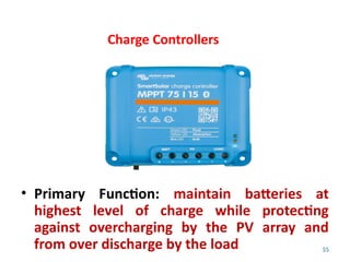
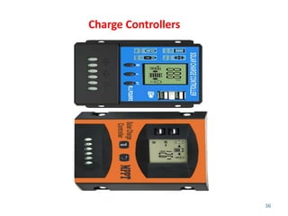
Charge Controllers
• PrimaryFunction: maintain batteries at
highest level of charge while protecting
against overcharging by the PV array and
from over discharge by the load
57
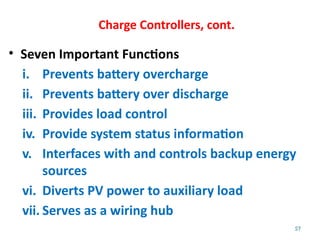
Charge Controllers, cont.
•Seven Important Functions
i. Prevents battery overcharge
ii. Prevents battery over discharge
iii. Provides load control
iv. Provide system status information
v. Interfaces with and controls backup energy
sources
vi. Diverts PV power to auxiliary load
vii. Serves as a wiring hub
58.
58
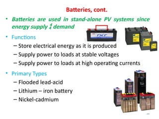
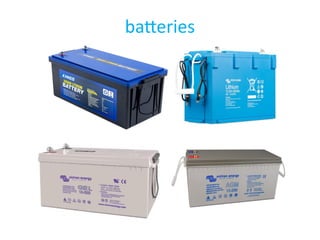
Batteries, cont.
• Batteriesare used in stand-alone PV systems since
energy supply demand
• Functions
– Store electrical energy as it is produced
– Supply power to loads at stable voltages
– Supply power to loads at high operating currents
• Primary Types
– Flooded lead-acid
– Lithium – iron battery
– Nickel-cadmium
60
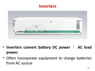
Inverters
• Inverters convertbattery DC power AC load
power.
• Often incorporate equipment to charge batteries
from AC source
61.
61
Inverters
Types of inverter
1.Modified Sine wave inverter
2. Pure sine wave inverter
3. Sqaure wave inverter
And this can be off- grid , or hybrid
62.
Mounting system &balance of
system(BoS)
i. Electrical BoS
Disconnect & protection devices
Grounding equipment
ii. Mechanical BoS
Array support & alignment
structures
Enclosures
Ventilation
63.
Module 4: SystemTypes and Design
Principles
• Off-grid, grid-tied, hybrid systems
• Practical: Use tools to design a PV system
64.
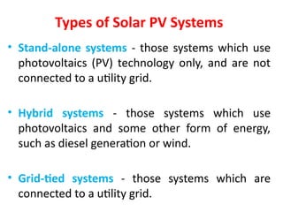
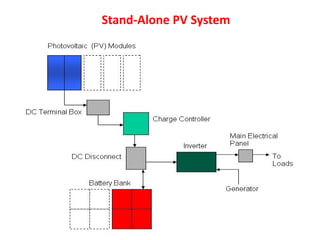
Types of SolarPV Systems
• Stand-alone systems - those systems which use
photovoltaics (PV) technology only, and are not
connected to a utility grid.
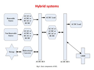
• Hybrid systems - those systems which use
photovoltaics and some other form of energy,
such as diesel generation or wind.
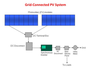
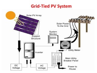
• Grid-tied systems - those systems which are
connected to a utility grid.
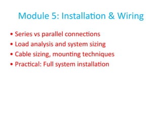
Module 5: Installation& Wiring
• Series vs parallel connections
• Load analysis and system sizing
• Cable sizing, mounting techniques
• Practical: Full system installation
71.
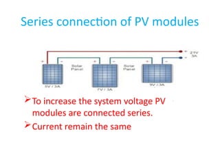
Series connection ofPV modules
To increase the system voltage PV
modules are connected series.
Current remain the same
72.
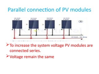
Parallel connection ofPV modules
To increase the system voltage PV modules are
connected series.
Voltage remain the same
73.
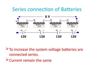
Series connection ofBatteries
To increase the system voltage batteries are
connected series.
Current remain the same
74.
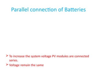
Parallel connection ofBatteries
To increase the system voltage PV modules are connected
series.
Voltage remain the same
Bracket Mounting Systems
•A simple bracket system can he used to mount a
single solar module. Two galvanized steel angle
brackets are bolted to a building's exterior walls or
roof structure. A second pair of compatible brackets
is attached to the end frames of the solar module.
When the two sets of brackets are mated, they form
a simple, durable, cost effective mounting system for
a one module photovoltaic system.
• Bracket systems can be constructed to pivot and tilt
to seasonally optimize the photovoltaic system's
performance.
77.
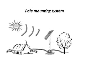
Pole Mounting Systems
•Arrays can also be mounted on a hardware
system that bolts directly to a vertical pole
placed permanently and securely in the
ground. Generally, 2½ inch steel pipe works
well for the base support. Pole mounting
hardware can be bought or fabricated out of
19-gauge stainless steel. This popular mounting
technique can be seasonally adjusted to
optimise the system's performance.
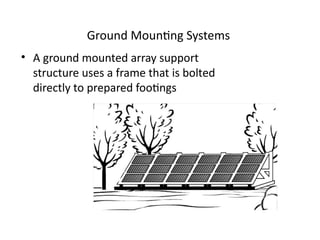
Ground Mounting Systems
•A ground mounted array support
structure uses a frame that is bolted
directly to prepared footings
81.
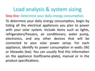
Load analysis &system sizing
Step 0ne: Determine your daily energy consumption.
To determine your daily energy consumption, begin by
listing all the electrical appliances you plan to power
with your solar system. Include items such as lights,
refrigerators/freezers, air conditioners, water pump,
electronics, and any other devices that will be
connected to your solar power setup. For each
appliance, identify its power consumption in watts (W)
or kilowatts (kw). You can usually find this information
on the appliance itself(name-plate), manual or in the
product specifications.
82.
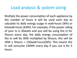
Load analysis &system sizing
Multiply the power consumption of each appliance by
the number of hours it will be used each day to
calculate its daily energy usage in watt-hours (Wh) or
kilowatt-hours (kWh). For example, if the power rating
of your tv is 30watts and you will be using the tv for
5hours every day, the daily energy consumption of
the tv will be 30W multiplied by 5hours; this will be
30W x 5hours = 150watt-hours(Wh). This means the
tv will consume 150Wh every day if you use it for 5
hours.
83.
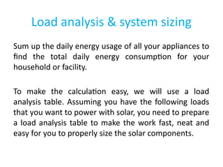
Load analysis &system sizing
Sum up the daily energy usage of all your appliances to
find the total daily energy consumption for your
household or facility.
To make the calculation easy, we will use a load
analysis table. Assuming you have the following loads
that you want to power with solar, you need to prepare
a load analysis table to make the work fast, neat and
easy for you to properly size the solar components.
85.
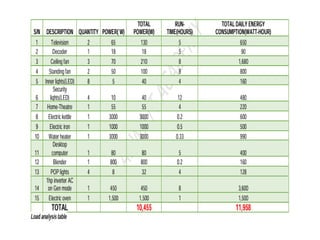
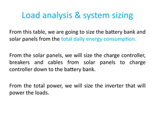
Load analysis &system sizing
From this table, we are going to size the battery bank and
solar panels from the total daily energy consumption.
From the solar panels, we will size the charge controller,
breakers and cables from solar panels to charge
controller down to the battery bank.
From the total power, we will size the inverter that will
power the loads.
86.
Load analysis &system sizing
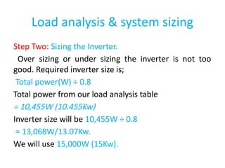
Step Two: Sizing the Inverter.
Over sizing or under sizing the inverter is not too
good. Required inverter size is;
Total power(W) ÷ 0.8
Total power from our load analysis table
= 10,455W (10.455Kw)
Inverter size will be 10,455W ÷ 0.8
= 13,068W/13.07Kw.
We will use 15,000W (15Kw).
87.
Load analysis &system sizing
Loads such as water pumps, air-conditioners and
refrigerators create brief power surges during
operation. The inverter must be sized to handle
these surges. Most modern inverters can handle
surges of 2 to 3 times their rated power output.
Surges last for few seconds. You should also
consider future loads when selecting the size of
your inverter.
88.
Load analysis &system sizing
Step Three: Sizing the battery bank.
Remember that the battery serves a reservoir to store all
the energy that is generated by the solar panels. You
need to properly size a battery bank for an off-grid
system to supply the required energy when the sun is not
available. Before sizing the battery bank, there are a few
things you need to take into consideration;
1. Inverter efficiency: there are losses when the inverter
is converting from DC to AC. With these losses, no
inverter can deliver 100 percent of the energy from a
battery bank to the loads. Most have 0.85 efficiency
89.
Load analysis &system sizing
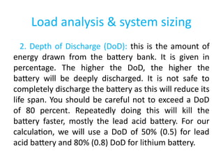
2. Depth of Discharge (DoD): this is the amount of
energy drawn from the battery bank. It is given in
percentage. The higher the DoD, the higher the
battery will be deeply discharged. It is not safe to
completely discharge the battery as this will reduce its
life span. You should be careful not to exceed a DoD
of 80 percent. Repeatedly doing this will kill the
battery faster, mostly the lead acid battery. For our
calculation, we will use a DoD of 50% (0.5) for lead
acid battery and 80% (0.8) DoD for lithium battery.
90.
Load analysis &system sizing
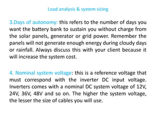
3.Days of autonomy: this refers to the number of days you
want the battery bank to sustain you without charge from
the solar panels, generator or grid power. Remember the
panels will not generate enough energy during cloudy days
or rainfall. Always discuss this with your client because it
will increase the system cost.
4. Nominal system voltage: this is a reference voltage that
must correspond with the inverter DC input voltage.
Inverters comes with a nominal DC system voltage of 12V,
24V, 36V, 48V and so on. The higher the system voltage,
the lesser the size of cables you will use.
91.
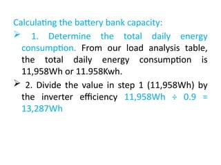
Calculating the batterybank capacity:
1. Determine the total daily energy
consumption. From our load analysis table,
the total daily energy consumption is
11,958Wh or 11.958Kwh.
2. Divide the value in step 1 (11,958Wh) by
the inverter efficiency 11,958Wh ÷ 0.9 =
13,287Wh
92.
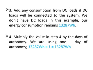
3. Add anyconsumption from DC loads if DC
loads will be connected to the system. We
don’t have DC loads in this example, our
energy consumption remains 13287Wh.
4. Multiply the value in step 4 by the days of
autonomy. We are using one – day of
autonomy; 13287Wh × 1 = 13287Wh
93.
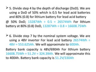
5. Dividestep 4 by the depth of discharge (DoD). We are
using a DoD of 50% which is 0.5 for lead acid batteries
and 80% (0.8) for lithium battery For lead acid battery
@ 50% DoD; 13287Wh ÷ 0.5 = 26574Wh For lithium
battery at 80% (0.8) DoD, 13287Wh ÷ 0.8 = 16608.75Wh
6. Divide step 7 by the nominal system voltage. We are
using a 48V inverter For lead acid battery 26574Wh ÷
48V = 553.625Ah. We will approximate to 600Ah.
Battery bank capacity is 48V/690Ah For lithium battery
16608.75Wh ÷ 51.2V = 324.39Ah. We will approximate this
to 400Ah. Battery bank capacity is 51.2V/330Ah
94.
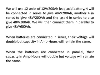
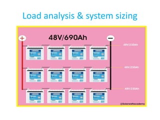
We will use12 units of 12V/200Ah lead acid battery, 4 will
be connected in series to give 48V/200Ah, another 4 in
series to give 48V/200Ah and the last 4 in series to also
give 48V/200Ah. We will then connect them in parallel to
give 48V/600Ah.
When batteries are connected in series, their voltage will
double but capacity in Amp-Hours will remain the same.
When the batteries are connected in parallel, their
capacity in Amp-Hours will double but voltage will remain
the same.
Load analysis &system sizing
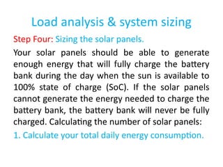
Step Four: Sizing the solar panels.
Your solar panels should be able to generate
enough energy that will fully charge the battery
bank during the day when the sun is available to
100% state of charge (SoC). If the solar panels
cannot generate the energy needed to charge the
battery bank, the battery bank will never be fully
charged. Calculating the number of solar panels:
1. Calculate your total daily energy consumption.
97.
Load analysis &system sizing
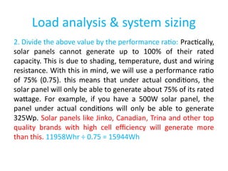
2. Divide the above value by the performance ratio: Practically,
solar panels cannot generate up to 100% of their rated
capacity. This is due to shading, temperature, dust and wiring
resistance. With this in mind, we will use a performance ratio
of 75% (0.75). this means that under actual conditions, the
solar panel will only be able to generate about 75% of its rated
wattage. For example, if you have a 500W solar panel, the
panel under actual conditions will only be able to generate
325Wp. Solar panels like Jinko, Canadian, Trina and other top
quality brands with high cell efficiency will generate more
than this. 11958Whr ÷ 0.75 = 15944Wh
98.
Load analysis &system sizing
3. Divide the above value by the peak sun hours (PSH):
this is the availability of sunshine in a given area per
day. On the average, how many hours of sunshine do
you have in your location? We will use 4 hours as our
peak sunshine hours. 15944Wh ÷ 5hours = 3188.8Wp.
4. Determine the number of solar panels by dividing
step 3 by the power rating of the solar panel you want
to use for the installation. Here, we are going to use a
500Wp Trina solar panel.
99.
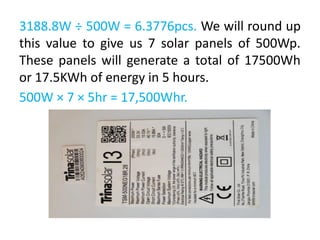
3188.8W ÷ 500W= 6.3776pcs. We will round up
this value to give us 7 solar panels of 500Wp.
These panels will generate a total of 17500Wh
or 17.5KWh of energy in 5 hours.
500W × 7 × 5hr = 17,500Whr.
100.
Load analysis &system sizing
Step Five: Sizing the solar charge controller.
The solar charge controller is in between the solar
panel and the battery bank. The charge controller
must be large enough to handle the current and
voltage generated by the solar panels. In some cases,
where you have a large system, you may use more
than one charge controller in your system. Each charge
controller will be connected to a separate array, but
they will be connected to the same battery bank.
101.
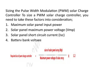
Sizing the PulseWidth Modulation (PWM) solar Charge
Controller To size a PWM solar charge controller, you
need to take these factors into consideration;
1. Maximum solar panel input power
2. Solar panel maximum power voltage (Vmp)
3. Solar panel short circuit current (Isc)
4. Battery bank voltage
102.
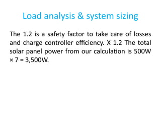
Load analysis &system sizing
The 1.2 is a safety factor to take care of losses
and charge controller efficiency. X 1.2 The total
solar panel power from our calculation is 500W
× 7 = 3,500W.
103.
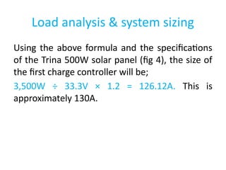
Load analysis &system sizing
Using the above formula and the specifications
of the Trina 500W solar panel (fig 4), the size of
the first charge controller will be;
3,500W ÷ 33.3V × 1.2 = 126.12A. This is
approximately 130A.
104.
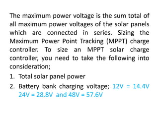
The maximum powervoltage is the sum total of
all maximum power voltages of the solar panels
which are connected in series. Sizing the
Maximum Power Point Tracking (MPPT) charge
controller. To size an MPPT solar charge
controller, you need to take the following into
consideration;
1. Total solar panel power
2. Battery bank charging voltage; 12V = 14.4V
24V = 28.8V and 48V = 57.6V
105.
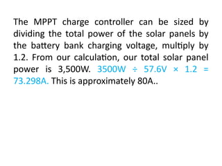
The MPPT chargecontroller can be sized by
dividing the total power of the solar panels by
the battery bank charging voltage, multiply by
1.2. From our calculation, our total solar panel
power is 3,500W. 3500W ÷ 57.6V × 1.2 =
73.298A. This is approximately 80A..
106.
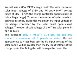
We will usea 80A MPPT charge controller with maximum
solar input voltage of 175V and PV array MPPT voltage
range of 60V – 170V (the charge controller operates best at
this voltage range). To know the number of solar panels to
connect in series, divide the maximum PV input voltage of
the charge controller by the solar panel open circuit
voltage. The open circuit voltage of the Trina solar panel in
fig 4 is 40.1V
This becomes 150V ÷ 40.1V = 3.74 pcs. We can only
connect a maximum of 3 panels in series. Do not
approximate to 4 pcs because the PV input voltage of the
solar panels will be greater than the PV input voltage of the
charge controller. Doing this will damage the controller.
107.
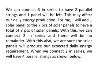
We can connect3 in series to have 2 parallel
strings and 1 panel will be left. This may affect
our daily energy production. For me, I will add 1
solar panel to the 7 pcs of solar panels to have a
total of 8 pcs of solar panels. With this, we can
connect 2 in series and there will be no
remainder. With this also, we are sure the solar
panels will produce our expected daily energy
requirement. When we connect 2 in series, we
will have 4 parallel strings as shown below.
109.
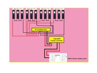
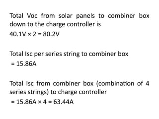
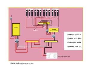
Total Voc fromsolar panels to combiner box
down to the charge controller is
40.1V × 2 = 80.2V
Total Isc per series string to combiner box
= 15.86A
Total Isc from combiner box (combination of 4
series strings) to charge controller
= 15.86A × 4 = 63.44A
110.
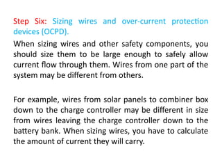
Step Six: Sizingwires and over-current protection
devices (OCPD).
When sizing wires and other safety components, you
should size them to be large enough to safely allow
current flow through them. Wires from one part of the
system may be different from others.
For example, wires from solar panels to combiner box
down to the charge controller may be different in size
from wires leaving the charge controller down to the
battery bank. When sizing wires, you have to calculate
the amount of current they will carry.
111.
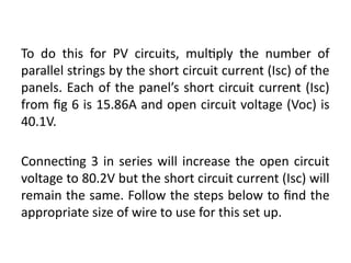
To do thisfor PV circuits, multiply the number of
parallel strings by the short circuit current (Isc) of the
panels. Each of the panel’s short circuit current (Isc)
from fig 6 is 15.86A and open circuit voltage (Voc) is
40.1V.
Connecting 3 in series will increase the open circuit
voltage to 80.2V but the short circuit current (Isc) will
remain the same. Follow the steps below to find the
appropriate size of wire to use for this set up.
112.
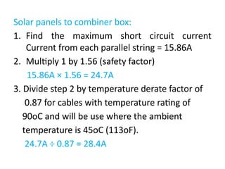
Solar panels tocombiner box:
1. Find the maximum short circuit current
Current from each parallel string = 15.86A
2. Multiply 1 by 1.56 (safety factor)
15.86A × 1.56 = 24.7A
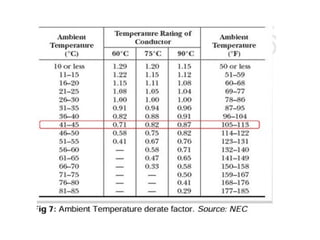
3. Divide step 2 by temperature derate factor of
0.87 for cables with temperature rating of
90oC and will be use where the ambient
temperature is 45oC (113oF).
24.7A ÷ 0.87 = 28.4A
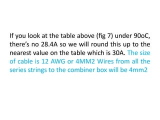
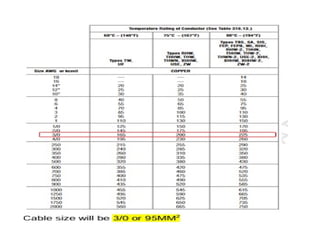
116.
If you lookat the table above (fig 7) under 90oC,
there’s no 28.4A so we will round this up to the
nearest value on the table which is 30A. The size
of cable is 12 AWG or 4MM2 Wires from all the
series strings to the combiner box will be 4mm2
117.
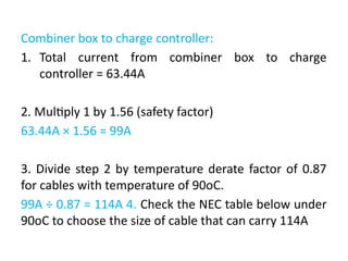
Combiner box tocharge controller:
1. Total current from combiner box to charge
controller = 63.44A
2. Multiply 1 by 1.56 (safety factor)
63.44A × 1.56 = 99A
3. Divide step 2 by temperature derate factor of 0.87
for cables with temperature of 90oC.
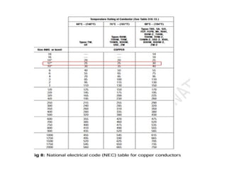
99A ÷ 0.87 = 114A 4. Check the NEC table below under
90oC to choose the size of cable that can carry 114A
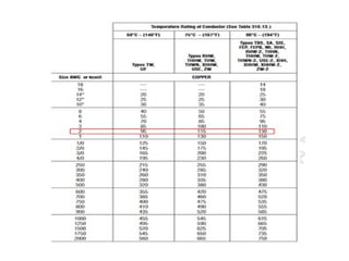
119.
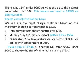
There is no114A under 90oC so we round up to the nearest
value which is 130A. This means we need a 2AWG or
35MM2 cable.
Charge controller to battery bank:
We will size the mppt charge controller based on the
maximum charging current which is 120A.
1. Total current from charge controller = 120A
2. Multiply 1 by 1.25 (safety factor) 120A × 1.25 = 150A
3. Divide step 2 by temperature derate factor of 0.87 for
cables with temperature of 90oC
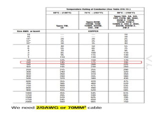
150A ÷ 0.87 = 172.4A 3. Check the NEC table below under
90oC to choose the size of cable that can carry 172.4A
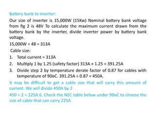
121.
Battery bank toinverter:
Our size of inverter is 15,000W (15Kw) Nominal battery bank voltage
from fig 2 is 48V To calculate the maximum current drawn from the
battery bank by the inverter, divide inverter power by battery bank
voltage.
15,000W ÷ 48 = 313A
Cable size:
1. Total current = 313A
2. Multiply 1 by 1.25 (safety factor) 313A × 1.25 = 391.25A
3. Divide step 2 by temperature derate factor of 0.87 for cables with
temperature of 90oC. 391.25A ÷ 0.87 = 450A.
It may be difficult to get a cable size that will carry this amount of
current. We will divide 450A by 2
450 ÷ 2 = 225A 6. Check the NEC table below under 90oC to choose the
size of cable that can carry 225A
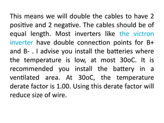
123.
This means wewill double the cables to have 2
positive and 2 negative. The cables should be of
equal length. Most inverters like the victron
inverter have double connection points for B+
and B- . I advise you install the batteries where
the temperature is low, at most 30oC. It is
recommended you install the battery in a
ventilated area. At 30oC, the temperature
derate factor is 1.00. Using this derate factor will
reduce size of wire.
125.
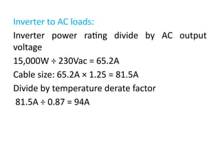
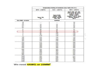
Inverter to ACloads:
Inverter power rating divide by AC output
voltage
15,000W ÷ 230Vac = 65.2A
Cable size: 65.2A × 1.25 = 81.5A
Divide by temperature derate factor
81.5A ÷ 0.87 = 94A
127.
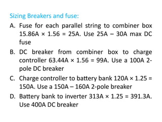
Sizing Breakers andfuse:
A. Fuse for each parallel string to combiner box
15.86A × 1.56 = 25A. Use 25A – 30A max DC
fuse
B. DC breaker from combiner box to charge
controller 63.44A × 1.56 = 99A. Use a 100A 2-
pole DC breaker
C. Charge controller to battery bank 120A × 1.25 =
150A. Use a 150A – 160A 2-pole breaker
D. Battery bank to inverter 313A × 1.25 = 391.3A.
Use 400A DC breaker
129.
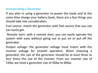
Incorporating a Generator
Ifyou plan in using a generator to power the loads and at the
same time charge your battery bank, there are a few things you
should take into consideration.
Fuel source: match the generator with fuel source that you can
can easily get.
Remote start: with a remote start, you can easily operate the
system with ease without going out to put on or put off the
generator.
Output voltage: the generator voltage must match with the
inverter voltage for smooth operation. When choosing a
generator, the size of the generator should be at least three to
four times the size of the inverter. From our inverter size of
15Kw, we need a generator size of 45Kw to 60Kw.
Module 6: Troubleshooting& Maintenance
• Common system faults
• Preventive maintenance steps
• Practical: Simulated fault diagnosis
134.
MAINTENANCE AND TROUBLESHOOTINGOF PHOTOVOLTAIC SYSTEM
Maintaining Photovoltaic System Components
Although PV power systems require little
maintenance compared to other power
systems, you should periodically perform a few
simple maintenance tasks.
135.
Photovoltaic Array
Checkthe panels for dust, if the system is in a
dusty climate with little rain, the panels may
need to be cleaned periodically. Clean the
modules with water and mild soap. Avoid
solvents or strong detergents.
Check to see if there are any shade problems due
to vegetation or a new building. If there are,
make arrangements for removing the vegetation
or moving the panels to a shade-free place.
136.
Check the panelmounting to make
sure that it is strong and well
attached.
If it is broken or loose, repair it
Check that the glass of the panels is
not broken. If it is, the panel will
have to be replaced.
The junction boxes should be
checked periodically for weather
protection, tightness of wires and
water seals
137.
Batteries MAINTENANCE
• Batterymaintenance depends largely on battery type,
though all batteries require periodic inspection to
verify system operation.
• Check connections for tightness and corrosion. Clean
and tighten as needed
• Cover connections with heavy grease. Do not get the
grease on any part of the battery except the
connections
• Clean the battery with fresh water and a rag. The acid
and the corrosion on the battery top should be
washed off with the cloth moistened with baking soda
or ammonia and water.
138.
Module 7: Costing& Customer Service
• System costing principles
• Quotation preparation
• Practical: Mock client engagement
139.
Module 8: FinalProject & Evaluation
• Group installation task
• Written & oral evaluation
• Certification criteria
Editor's Notes
#64 There are basically three types of photovoltaic systems. The stand alone systems use photovoltaics technology only, and are not connected to a utility grid. The usually have some form of backup. The second type of system is the hybrid system. Hybrid systems are made up of PV and some other forms of energy production, such as wind or diesel generation. Finally, grid-tied systems do not necessarily need backup at all and are tied directly to the utility grid. The grid stores the energy. For example, if you have a PV system on your house, and it produces more energy than needed, the extra will go back onto the grid. So during cloudy days or at night, you can pull the energy from the grid into your home.
Source:
http://www.sandia.gov/pv/docs/Design_and_Installation_of_PV_Systems.htm
#67 Most of us are interested in grid-tied systems because most of us are connected on grid system houses, so if you don’t have a ranch or a cottage up in the country, you get your electricity from a grid. For this type of system it is very feasible to put a solar array on your roof. Here you have solar panel array on your roof, sun shines on it and produces a DC voltage (like a battery). Then it runs through the inverter and turns into AC Voltage (like the electricity that comes from a wall outlet). The inverter is usually monitored in some way. Usually you’ll have a panel inside your home. AC voltage goes straight to the main utility breaker panel. From there it can be used to power any electrical device in your home. In cases, lets say, at lunch time, if you’re at work, and the solar cell is doing really good because it’s a sunny day out, you’re going to be producing a lot of electricity, and then it can be fed back into grid and spin your utility meter backwards. You then only pay for the net amount of electricity you use. This is called net metering. You are only paying for the net amount of electricity you are consuming. Some solar users purposely make more electricity than they use so they can receive money back from the electric companies.
Base definitions for grid tied solar photovoltaic systems:
Solar Panels convert sunlight directly into electricity. The Inverter converts the solar electricity (DC) into household current (AC) that can be used to power loads in the house. The System Monitor is an easy-to-read digital meter that shows the homeowner the amount of electricity generated both cumulatively and daily. The Utility Meter tracks power usage and production, spinning forward when electricity is used from the grid, and spinning backwards, generating a credit, when the solar system creates more electricity than is used in the house.
Sources:
http://www.solarmarket.com/frontier.html
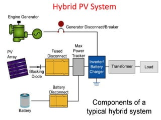
#69 This is a block diagram of a hybrid PV system. The PV array produces electricity, which goes through the blocking diode and the fused disconnect to get to the maximum power tracker. If you need electricity immediately, it runs though the inverter and transformer and goes to your load. Otherwise, it is stored in a battery. Then if it became dark out, you can draw the energy from the battery. If it is dark for a very long time, you can draw the energy from the diesel generator.
Source:
http://www.sandia.gov/pv/docs/BOS.htm