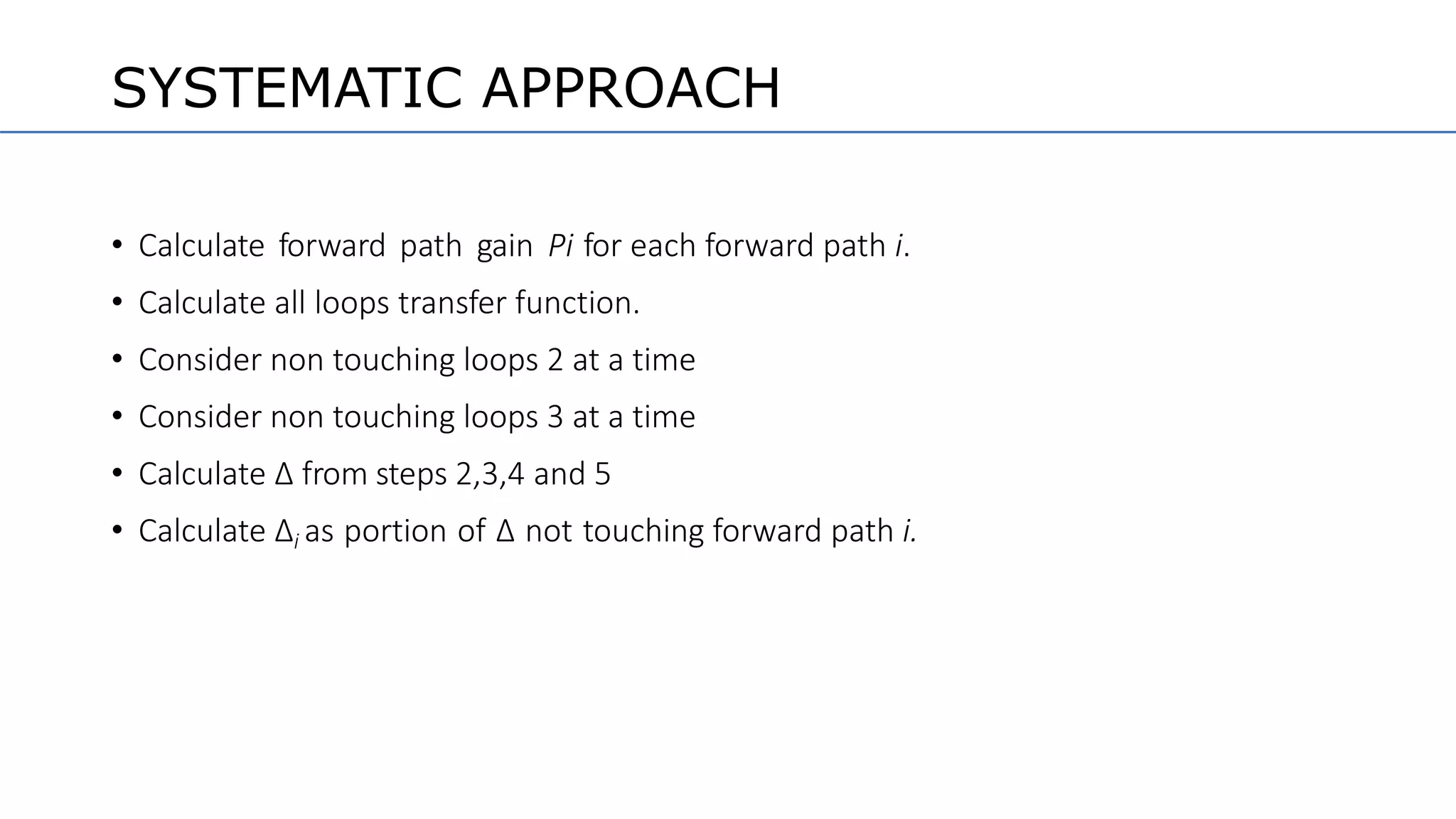
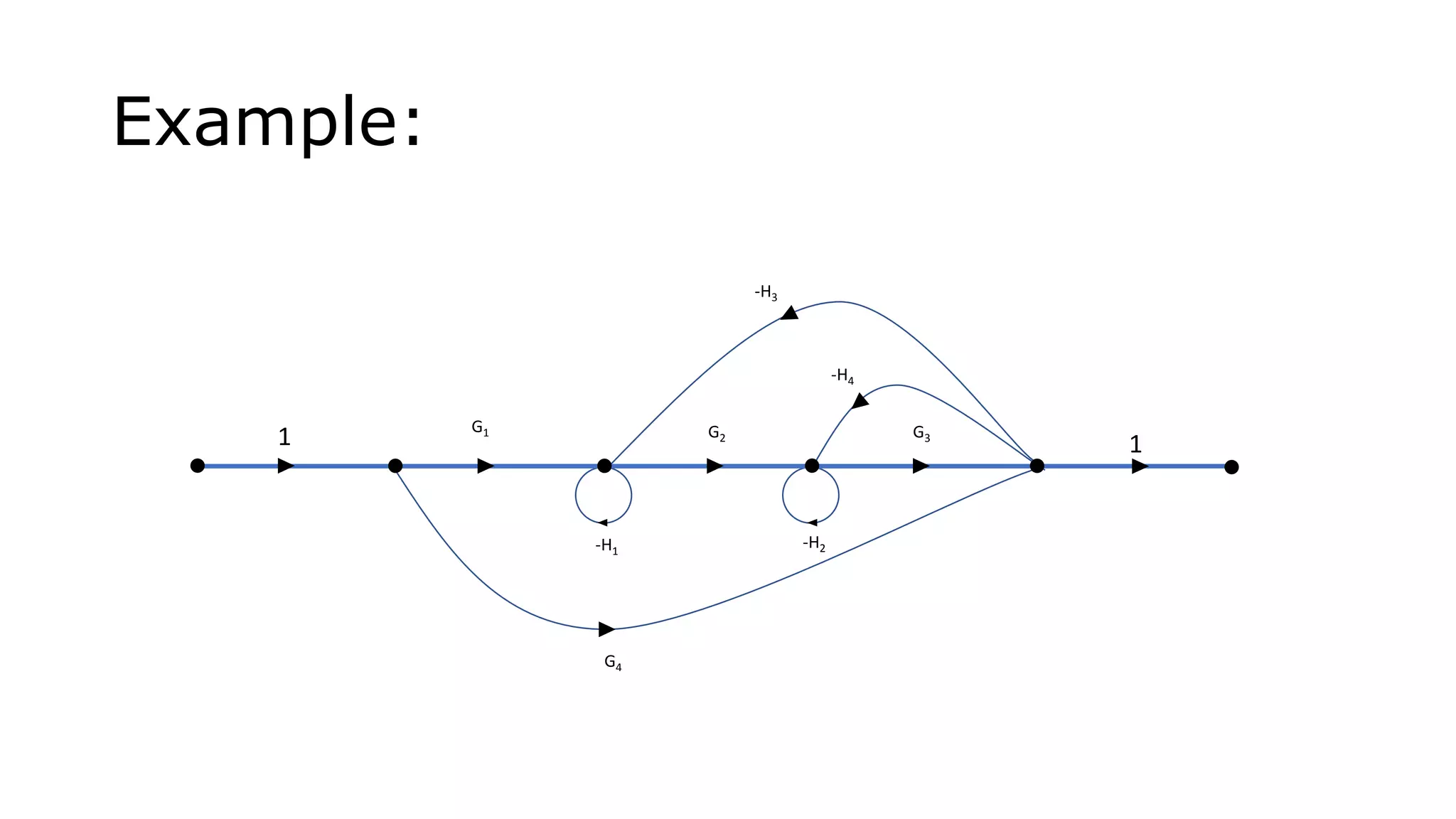
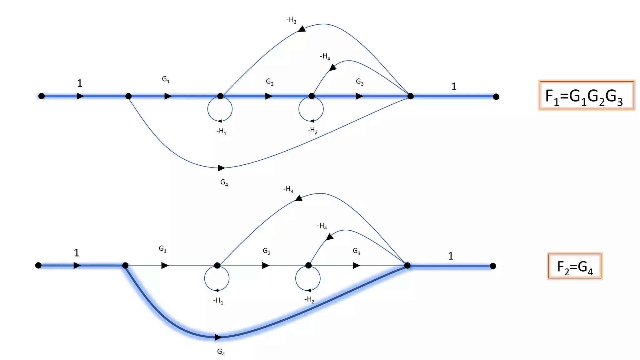
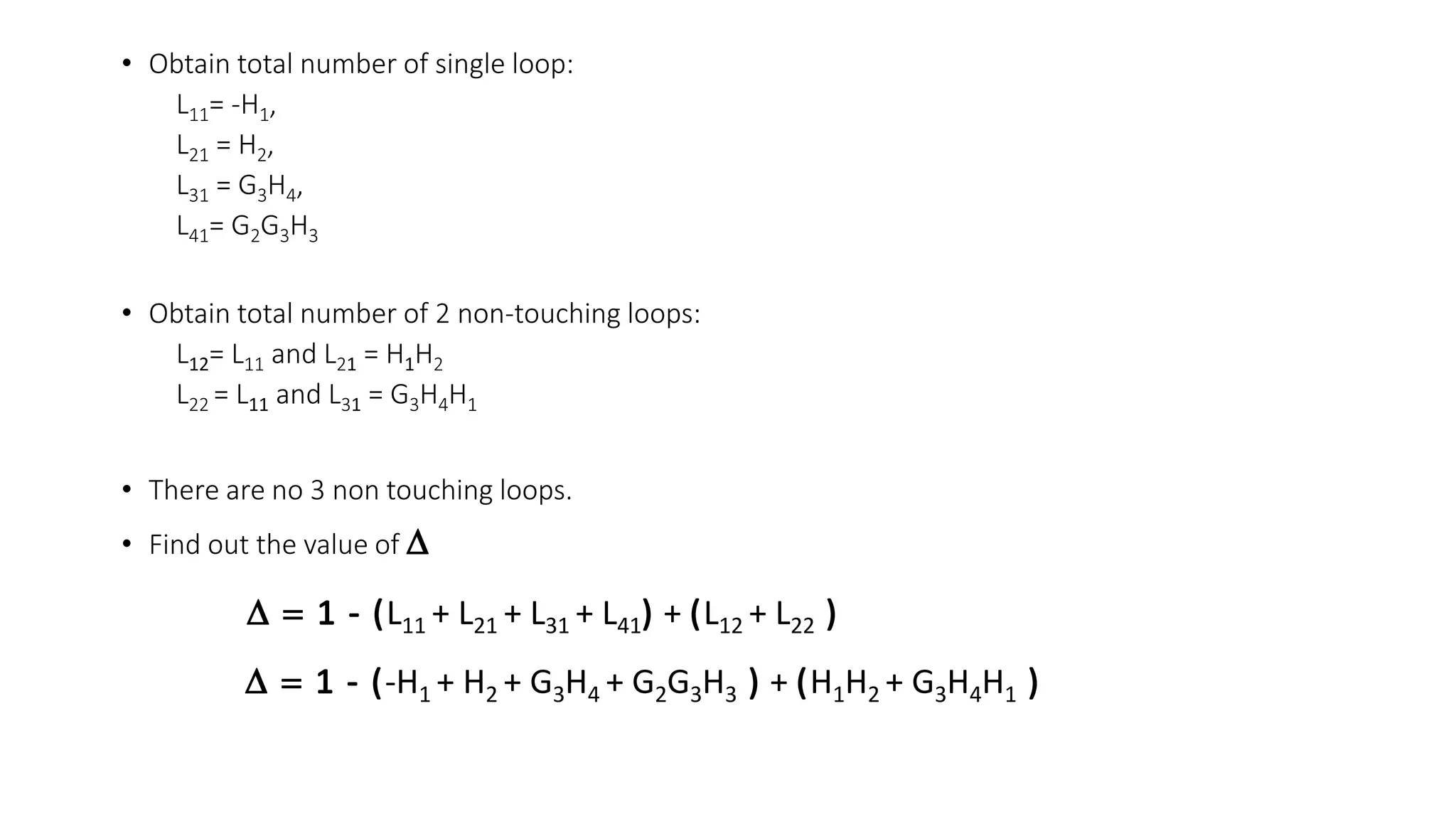
This document discusses signal flow graphs and Mason's rule for analyzing control systems. It begins with an introduction to signal flow graphs and their basic components and terminology. It then explains Mason's rule, which provides a formula for reducing a signal flow graph to a single transfer function. The formula relates the graph to the simultaneous equations that can be written from it. The document provides an example of applying Mason's rule to calculate the transfer function of a sample signal flow graph. It demonstrates identifying forward paths, calculating loop transmittances, and determining the characteristic function and path determinants.

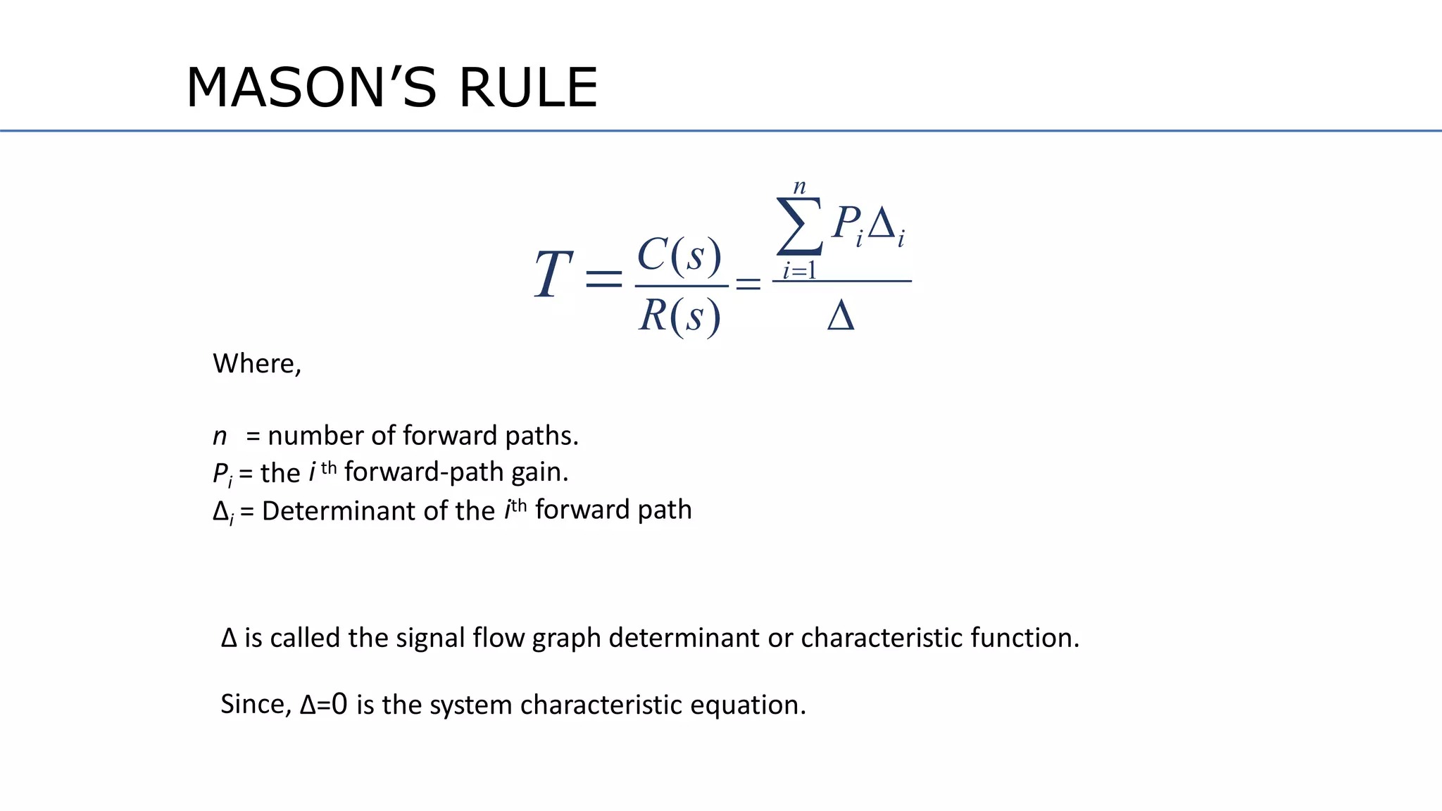
![∆ = 1- (sum of all individual loop transmittance) + (sumof the products of
loop transmittance of all possible pairs of Non Touching loops) – (sum of
the products of loop transmittance of Triple of Non Touching loop) + …
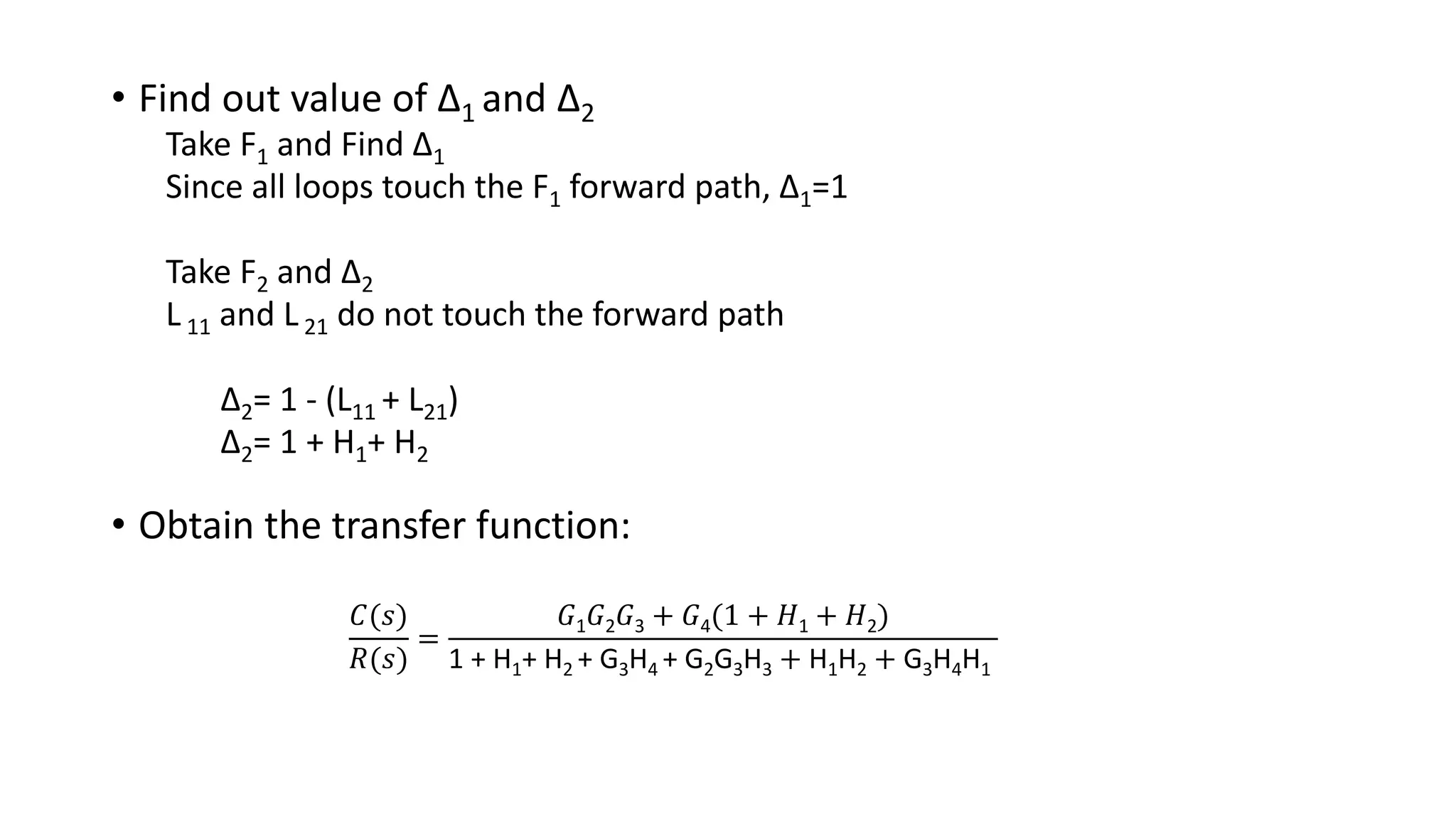
∆i = Calculate ∆ for ith path
=1- [loop transmittance of single Non Touching loops with forward path]
+ [loop transmittance of pair of Non Touching loops withforward path]
MASON’S RULE](https://image.slidesharecdn.com/cs-171004180735/75/Signal-Flow-Graph-8-2048.jpg)