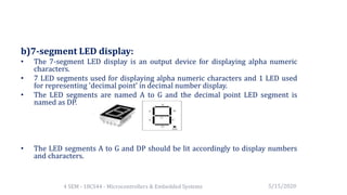
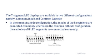
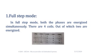
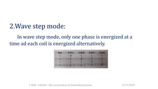
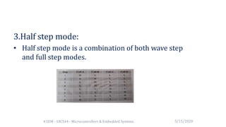
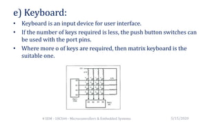
SENSORS, ACTUATORS &
I/O SUB SYSTEMS
4 SEM - 18CS44 - Microcontrollers & Embedded Systems 5/15/2020
Contents:
– LEDs
– 7-Segmet displays
– Stepper motor
– Push button switch
– Keyboard
4 SEM - 18CS44 - Microcontrollers & Embedded
Systems
5/15/2020
1. Sensors
2. Actuators
3. I/O Sub systems
1.Sensor:
• A sensor is a transducer device that converts energy
from one form to another.
• E.g.: Temperature sensor, magnetic Hall Effect sensor,
humidity sensor, etc
5/15/20204 SEM - 18CS44 - Microcontrollers & Embedded Systems
2. Actuator:
• An actuator is a form of transducer device
(mechanical or electrical) which converts signals to
corresponding physical action.
• Actuator acts as an output device.
– E.g.: Stepper motor
5/15/20204 SEM - 18CS44 - Microcontrollers & Embedded Systems
3. I/O Sub systems:
• The interaction happens through the sensors and actuators
connected to the input and output ports of the embedded
system.
• The sensors may not be directly interfaced to the input ports,
instead they may be interfaced through some I/O subsystems.
• Few of the I/O subsystems are explained here.
5/15/20204 SEM - 18CS44 - Microcontrollers & Embedded Systems
a)Light Emitting Diode (LED):
• Light Emitting Diode (LED) is an important output device for visual
indication in any embedded system.
• LED can be used as an indicator for the status of various
signals or situations.
• Light Emitting Diode is a p-n junction diode and it contains an anode
and a cathode.
5/15/20204 SEM - 18CS44 - Microcontrollers & Embedded Systems
LEDs can be interfaced to the port pin of a processor/controller in two
ways:
– In the first method, the anode is directly connected to the port pin
and the port pin drives the LED. Cathode is grounded. It is called
common cathode method.
– In the second method, the cathode of the LED is connected to the
port pin of the processor/controller and the anode to the supply
voltage through a current limiting resistor. It is called common
anode method.
5/15/20204 SEM - 18CS44 - Microcontrollers & Embedded Systems
b)7-segment LED display:
• The 7-segment LED display is an output device for displaying alpha numeric
characters.
• 7 LED segments used for displaying alpha numeric characters and 1 LED used
for representing 'decimal point' in decimal number display.
• The LED segments are named A to G and the decimal point LED segment is
named as DP.
• The LED segments A to G and DP should be lit accordingly to display numbers
and characters.
5/15/20204 SEM - 18CS44 - Microcontrollers & Embedded Systems
The 7-segment LED displays are available in two different configurations,
namely; Common Anode and Common Cathode.
• In the common anode configuration, the anodes of the 8 segments are
connected commonly whereas in the common cathode configuration,
the cathodes of 8 LED segments are connected commonly.
5/15/20204 SEM - 18CS44 - Microcontrollers & Embedded Systems
C)Stepper Motor:
• A stepper motor is an electromechanical device which
generates discreate rotations.
• Stepper motor is widely used in industrial embedded
applications, consumer electronics, robotics etc.
• Printer/fax machines uses stepper motor for its functioning.
5/15/20204 SEM - 18CS44 - Microcontrollers & Embedded Systems
• Based on the coil winding arrangements, 2 phase stepper motor is
classified into 2 types
1.Uipolar
2.Bipolar
There are 3 different stepping modes in stepper motor
1.Full step
2.Wave step
3.Half step
5/15/20204 SEM - 18CS44 - Microcontrollers & Embedded Systems
1.Full step mode:
In full step mode, both the phases are energized
simultaneously. There are 4 coils. Out of which two are
energized.
5/15/20204 SEM - 18CS44 - Microcontrollers & Embedded Systems
2.Wave step mode:
In wave step mode, only one phase is energized at a
time ad each coil is energized alternatively.
5/15/20204 SEM - 18CS44 - Microcontrollers & Embedded Systems
3.Half step mode:
• Half step mode is a combination of both wave step
and full step modes.
5/15/20204 SEM - 18CS44 - Microcontrollers & Embedded Systems
d)Push Button Switch:
• It is an input device.
• It comes in two configurations, namely 'Push to Make' and 'Push to
Break’.
– In the 'Push to Make' configuration, the switch is normally in the
open state and it makes a circuit contact when it is pushed or
pressed.
– In the 'Push to Break' configuration, the switch is normally in the
closed state and it breaks the circuit contact when it is pushed or
pressed.
5/15/20204 SEM - 18CS44 - Microcontrollers & Embedded Systems
• Depending on the way in which the push button
interfaced to the controller, it can generate either a
‘HIGH’ pulse or a 'LOW' pulse.
5/15/20204 SEM - 18CS44 - Microcontrollers & Embedded Systems
e) Keyboard:
• Keyboard is an input device for user interface.
• If the number of keys required is less, the push button switches can
be used with the port pins.
• Where more o of keys are required, then matrix keyboard is the
suitable one.
5/15/20204 SEM - 18CS44 - Microcontrollers & Embedded Systems

Sensors and Actuators

  • 1.
    SENSORS, ACTUATORS & I/OSUB SYSTEMS 4 SEM - 18CS44 - Microcontrollers & Embedded Systems 5/15/2020
  • 2.
    Contents: – LEDs – 7-Segmetdisplays – Stepper motor – Push button switch – Keyboard 4 SEM - 18CS44 - Microcontrollers & Embedded Systems 5/15/2020 1. Sensors 2. Actuators 3. I/O Sub systems
  • 3.
    1.Sensor: • A sensoris a transducer device that converts energy from one form to another. • E.g.: Temperature sensor, magnetic Hall Effect sensor, humidity sensor, etc 5/15/20204 SEM - 18CS44 - Microcontrollers & Embedded Systems
  • 4.
    2. Actuator: • Anactuator is a form of transducer device (mechanical or electrical) which converts signals to corresponding physical action. • Actuator acts as an output device. – E.g.: Stepper motor 5/15/20204 SEM - 18CS44 - Microcontrollers & Embedded Systems
  • 5.
    3. I/O Subsystems: • The interaction happens through the sensors and actuators connected to the input and output ports of the embedded system. • The sensors may not be directly interfaced to the input ports, instead they may be interfaced through some I/O subsystems. • Few of the I/O subsystems are explained here. 5/15/20204 SEM - 18CS44 - Microcontrollers & Embedded Systems
  • 6.
    a)Light Emitting Diode(LED): • Light Emitting Diode (LED) is an important output device for visual indication in any embedded system. • LED can be used as an indicator for the status of various signals or situations. • Light Emitting Diode is a p-n junction diode and it contains an anode and a cathode. 5/15/20204 SEM - 18CS44 - Microcontrollers & Embedded Systems
  • 7.
    LEDs can beinterfaced to the port pin of a processor/controller in two ways: – In the first method, the anode is directly connected to the port pin and the port pin drives the LED. Cathode is grounded. It is called common cathode method. – In the second method, the cathode of the LED is connected to the port pin of the processor/controller and the anode to the supply voltage through a current limiting resistor. It is called common anode method. 5/15/20204 SEM - 18CS44 - Microcontrollers & Embedded Systems
  • 8.
    b)7-segment LED display: •The 7-segment LED display is an output device for displaying alpha numeric characters. • 7 LED segments used for displaying alpha numeric characters and 1 LED used for representing 'decimal point' in decimal number display. • The LED segments are named A to G and the decimal point LED segment is named as DP. • The LED segments A to G and DP should be lit accordingly to display numbers and characters. 5/15/20204 SEM - 18CS44 - Microcontrollers & Embedded Systems
  • 9.
    The 7-segment LEDdisplays are available in two different configurations, namely; Common Anode and Common Cathode. • In the common anode configuration, the anodes of the 8 segments are connected commonly whereas in the common cathode configuration, the cathodes of 8 LED segments are connected commonly. 5/15/20204 SEM - 18CS44 - Microcontrollers & Embedded Systems
  • 10.
    C)Stepper Motor: • Astepper motor is an electromechanical device which generates discreate rotations. • Stepper motor is widely used in industrial embedded applications, consumer electronics, robotics etc. • Printer/fax machines uses stepper motor for its functioning. 5/15/20204 SEM - 18CS44 - Microcontrollers & Embedded Systems
  • 11.
    • Based onthe coil winding arrangements, 2 phase stepper motor is classified into 2 types 1.Uipolar 2.Bipolar There are 3 different stepping modes in stepper motor 1.Full step 2.Wave step 3.Half step 5/15/20204 SEM - 18CS44 - Microcontrollers & Embedded Systems
  • 12.
    1.Full step mode: Infull step mode, both the phases are energized simultaneously. There are 4 coils. Out of which two are energized. 5/15/20204 SEM - 18CS44 - Microcontrollers & Embedded Systems
  • 13.
    2.Wave step mode: Inwave step mode, only one phase is energized at a time ad each coil is energized alternatively. 5/15/20204 SEM - 18CS44 - Microcontrollers & Embedded Systems
  • 14.
    3.Half step mode: •Half step mode is a combination of both wave step and full step modes. 5/15/20204 SEM - 18CS44 - Microcontrollers & Embedded Systems
  • 15.
    d)Push Button Switch: •It is an input device. • It comes in two configurations, namely 'Push to Make' and 'Push to Break’. – In the 'Push to Make' configuration, the switch is normally in the open state and it makes a circuit contact when it is pushed or pressed. – In the 'Push to Break' configuration, the switch is normally in the closed state and it breaks the circuit contact when it is pushed or pressed. 5/15/20204 SEM - 18CS44 - Microcontrollers & Embedded Systems
  • 16.
    • Depending onthe way in which the push button interfaced to the controller, it can generate either a ‘HIGH’ pulse or a 'LOW' pulse. 5/15/20204 SEM - 18CS44 - Microcontrollers & Embedded Systems
  • 17.
    e) Keyboard: • Keyboardis an input device for user interface. • If the number of keys required is less, the push button switches can be used with the port pins. • Where more o of keys are required, then matrix keyboard is the suitable one. 5/15/20204 SEM - 18CS44 - Microcontrollers & Embedded Systems