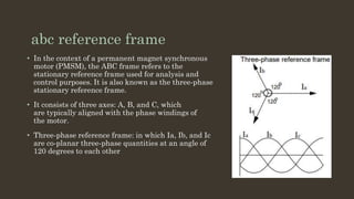
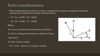
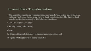
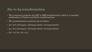
Reference frame theory provides a mathematical framework to analyze and control permanent magnet synchronous motors by transforming three-phase variables into rotating reference frames like the dq frame. This simplifies analysis and enables techniques like field-oriented control. The Clarke and Park transformations convert variables between stationary abc/αβ frames and the rotating dq frame. Clarke transforms from abc to αβ, and Park transforms between αβ and dq frames through rotation by the electrical angle. Transforming variables allows decoupling dynamics and more efficient analysis and control of electric machines.


![Clarke transformation
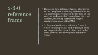
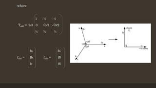
• The Clarke Transformation converts the time-domain components of a three-phase system in an
abc reference frame to components in a stationary ɑβ0 reference frame..
• This can preserve the active and reactive powers of the system in the abc frame.
• In order for the transformation to be invertible, a third variable, known as the zero-
sequence component, is added.
• The resulting transformation equation is given by
[ fαβ0 ] = T αβ0 [ fabc ]
Where f represents voltage, current, flux linkage or electric charge](https://image.slidesharecdn.com/theoryofreferenceframes-240330055423-7ad718e7/85/theory-of-reference-frames-and-its-types-11-320.jpg)
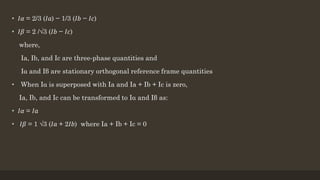
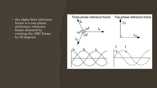
![Inverse clarke transformation
• The transformation from a two-axis orthogonal stationary reference frame to a three-
phase stationary reference frame is accomplished using Inverse Clarke
transformation a. The Inverse Clarke transformation is expressed by the following
equations:
[ fabc ] = T αβ0
-1 [ fαβ0 ]
1 0 1
Where Tαβ0
-1 = -½ √3/2 1
-½ -√3/2 1](https://image.slidesharecdn.com/theoryofreferenceframes-240330055423-7ad718e7/85/theory-of-reference-frames-and-its-types-14-320.jpg)


![[Deck] What's New in Spark-Iceberg Integration via DSV2.pptx](https://cdn.slidesharecdn.com/ss_thumbnails/deckwhatsnewinspark-icebergintegrationviadsv2-260210005337-25955b12-thumbnail.jpg?width=640&height=640&fit=bounds)


