Download as PDF, PPTX

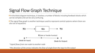
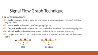
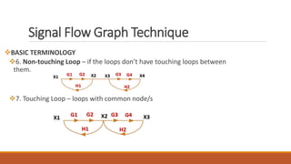
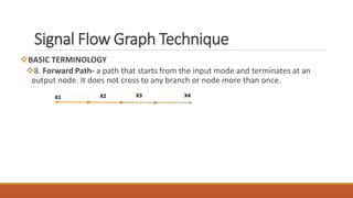
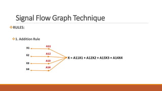
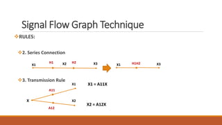
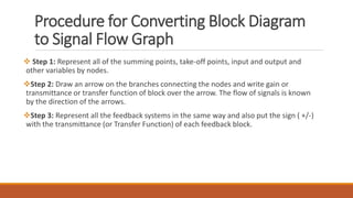
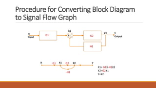
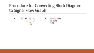
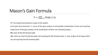
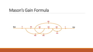
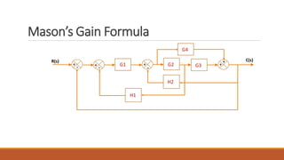


The document discusses signal flow graph techniques for representing and analyzing feedback control systems. It defines key signal flow graph terminology like nodes, loops, and paths. It also outlines rules for constructing a signal flow graph from a block diagram, including the addition, series connection, and transmission rules. Finally, it introduces Mason's Gain Formula for calculating the overall gain of a system from its signal flow graph representation.