Download to read offline


![ SIGNAL FLOW GRAPH REDUCTION
MASON’S GAIN FORMULA
ARASU
ENGINEERING
COLLEGE
IC 8451&CONTROL SYSTEMS
6
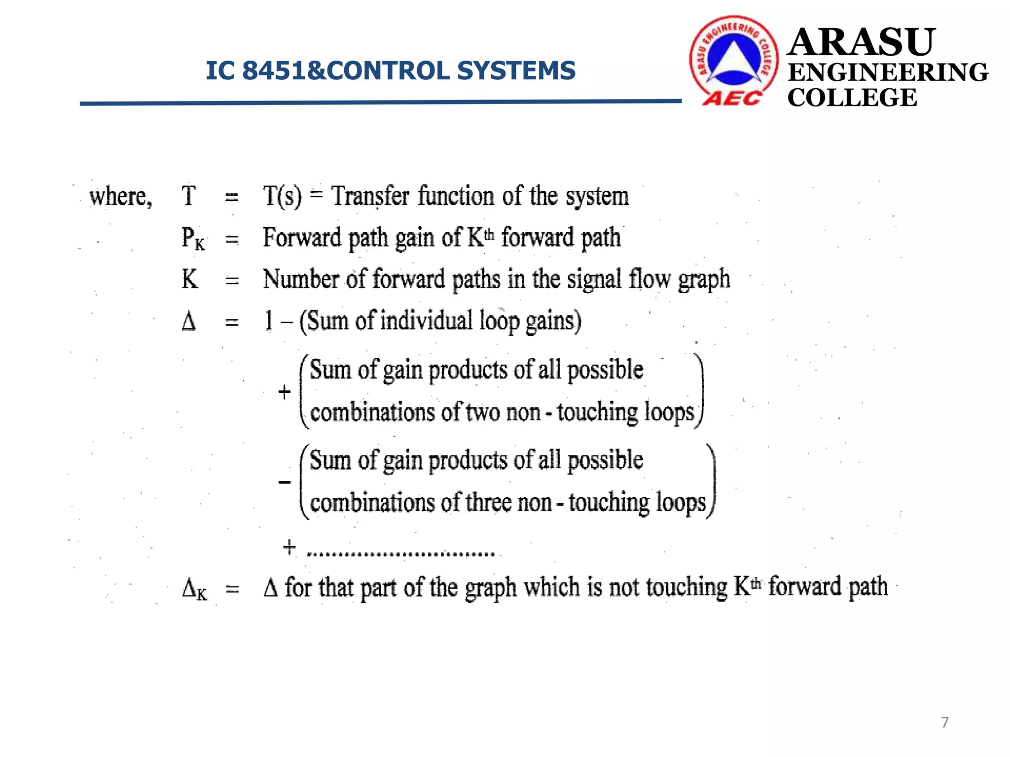
The Mason’s gain formula is used to determine the transfer function of the
system from the signal flow graph of the system.
Let, R(s) = Input to the system
C(s) = Output of the system
Now, Transfer function of the system, T(s) =
Mason’s gain formula states the overall gain of the system [transfer function] as
follows,
Overall gain,](https://image.slidesharecdn.com/signalflowgraphs-210209063341/75/Signal-flow-graphs-6-2048.jpg)


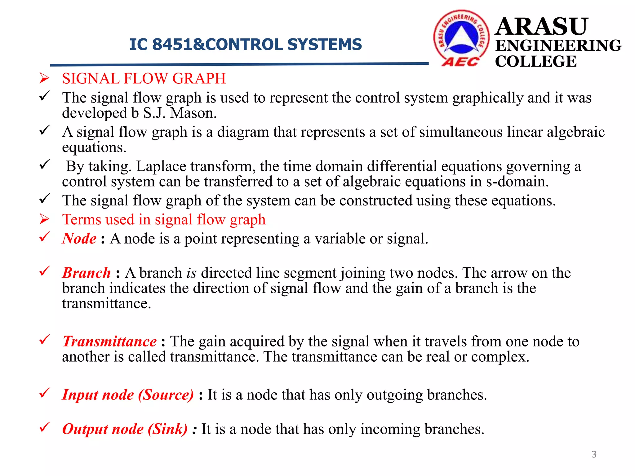
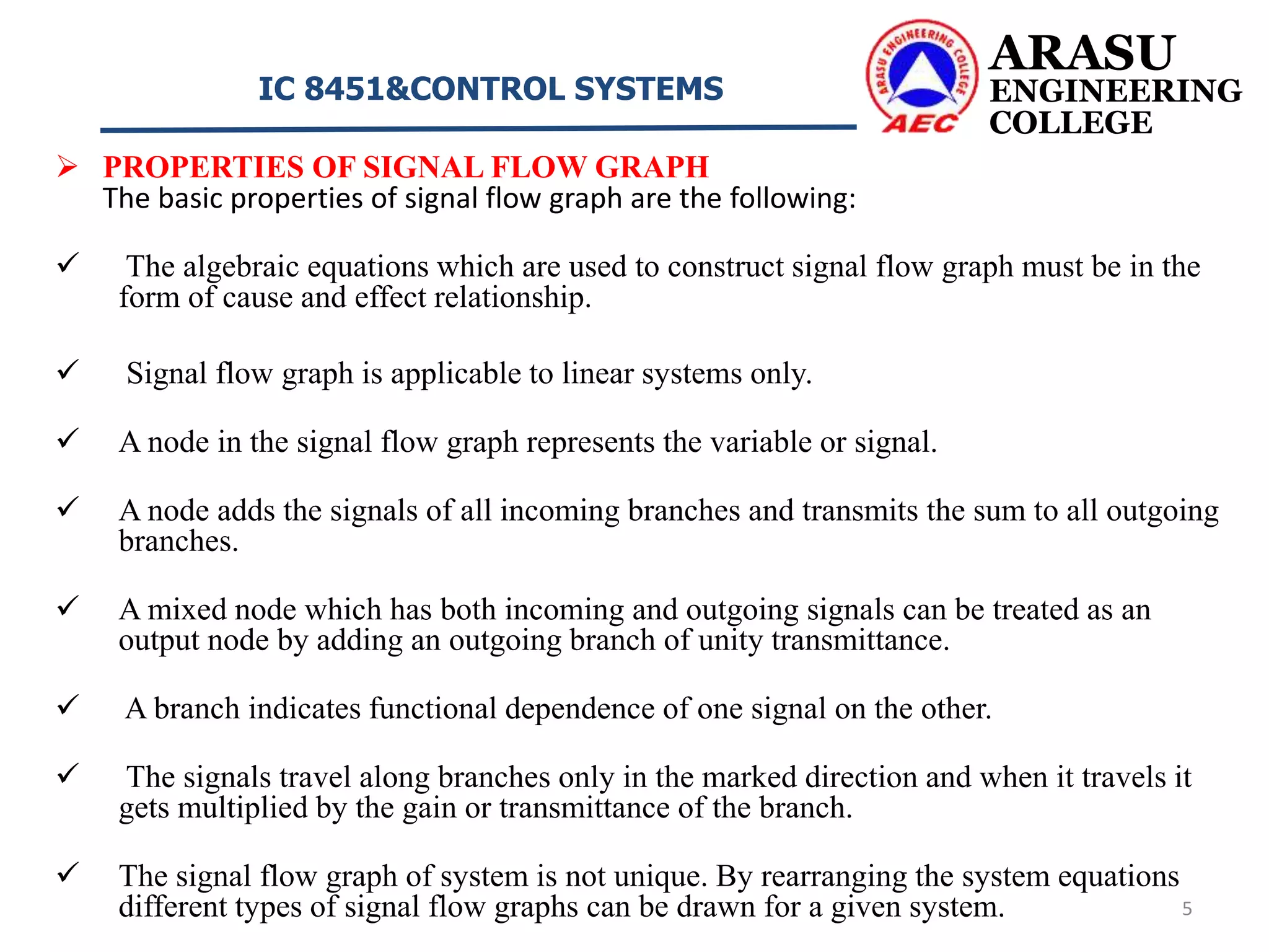
This document discusses signal flow graphs and Mason's gain formula for control systems. It begins by defining key terms used in signal flow graphs such as nodes, branches, transmittance, input/output nodes, paths, and loop gains. It then describes properties of signal flow graphs and how Mason's gain formula can be used to determine a system's transfer function from its signal flow graph. The document concludes by providing two example problems that demonstrate how to apply Mason's gain formula to calculate a system's overall transfer function.