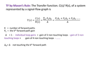
The document discusses signal flow graphs and Mason's rule for determining transfer functions from signal flow graphs. Mason's rule states that the transfer function is equal to the sum of the products of the forward path gains and the cofactors of the individual loops, divided by the overall cofactor. Several examples are provided to demonstrate applying Mason's rule to calculate transfer functions from given signal flow graphs.

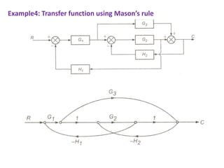
![Example1: Transfer function using Mason’s rule
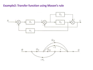
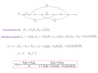
Forward path (1) : P1 = G1(s)G2(s)G3(s)G4(s)G5(s)
Loops(4): L1= G2(s)H1(s), L2=G4(s)H2(s), L3=G7(s)H4(s), L4=G2(s)G3(s)G4(s)G5(s)G6(s)G7(s)G8(s)
Two nontouching loops(3): L12= G2(s)H1(s)G4(s)H2(s), L13=G2(s)H1(s)G7(s)H4(s), L23=G4(s)H2(s)G7(s)H4(s)
Three nontouching loops(1): L123=G2(s)H1(s)G4(s)H2(s)G7(s)H4(s)
= 1-[G2(s)H1(s)+G4(s)H2(s)+G7(s)H4(s)+ G2(s)G3(s)G4(s)G5(s)G6(s)G7(s)G8(s)] + [G2(s)H1(s)G4(s)H2(s)
+ G2(s)H1(s)G7(s)H4(s) + G4(s)H2(s)G7(s)H4(s)] – [G2(s)H1(s)G4(s)H2(s)G7(s)H4(s)]
∆= 1 − (𝐿1 + 𝐿2+𝐿3+𝐿4)+(𝐿12+𝐿13 + 𝐿23) − 𝐿123
∆𝑘= ∆1= 1 − 𝐿3 = 1 − 𝐺7(𝑠)𝐻4(𝑠) 𝑇 𝑠 =
𝑃1∆1
∆](https://image.slidesharecdn.com/control11sfg3-240216165213-4806618b/85/Control_System-Signal-Flow-graph-11_SFG-3-pdf-7-320.jpg)