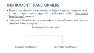
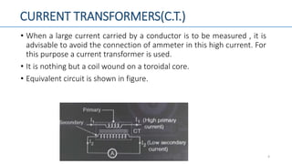
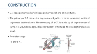
DC MACHINES AND TRANSFORMER
SPECIAL TRANSFORMER
PREET|patel (151310109032)
2ND YEAR B.E ELCETRICAL
AIIE
CONTENT
• Instrument Transformers
• Pulse Transformers
• Radio Frequency Transformers
• Audio Frequency Transformers
• Intermediate Frequency transformers
• Grounding Transformer
2
INSTRUMENT TRANSFORMERS
• There is a problem in measurement of high voltage and heavy currents.
In such cases special type of transformers called “Instrument
Transformers” are used.
• Instrument Transformers are accurate ratio transformers and they are
classified in two categories :-
Instrument transformers
Current Transformer Potential Transformer
3
CURRENT TRANSFORMERS(C.T.)
• When a large current carried by a conductor is to be measured , it is
advisable to avoid the connection of ammeter in this high current. For
this purpose a current transformer is used.
• It is nothing but a coil wound on a toroidal core.
• Equivalent circuit is shown in figure.
4
CONSTRUCTION
• C.T. has a primary coil which has a primary coil of one or more turns.
• The primary of C.T. carries the large current I1 which is to be measured, so it is of
large cross sectional area. The secondary of a C.T. is made up of large number of
turns. It is wound on a core. It is a low current winding so its cross sectional area is
small.
• Ammeter range
is of 0-5 A .
5
OPERATION
• C.T.is basically a step up transformer. Hence the secondary is a high
voltage low current winding. The current is stepped down.
• The secondary current is given by,
(Where, N2 >>>> N1 )
• The current I2 is measured by the ammeter. So if we know the turns
ratio N1/N2 then it is possible to measure I1.Thus a C.T. is used to
measure a high current without actually connecting the ammeter
directly in series
with the high current.
6
2
1
12
N
N
II 
ADVANTAGES
1. It is possible to use the ammeters of normal current range to measure very high currents.
2. We can calibrate the same ammeter to measure different currents by adjusting the turn
ratio of the C.T.
3. The C.T. can be used to operate indicating and protecting devices such as relays.
4. The same C.T. can be used to provide the measured current to several instruments.
5. The user is safe due to the isolation provided by the C.T. between high current primary and
low current secondary.
7
DISADVANTAGES
1. It can be used to measure only the ac current. The DC current can not be
measured.
2. C.T. can not be operated with open circuited secondary.
8
POTENTIAL TRANSFORMER(P.T.)
• It is another type of instrumentation transformer. It is used to measure high AC
voltage.
• Its construction is same as to the normal transformer.
• Its connection is shown in figure.
9
OPERATION
• To measure high voltage, the potential voltage transformer which is a step down
transformer is connected across high voltage terminals and voltmeter is
connected on low voltage side.
• A P.T. is an ordinary two winding transformer with high turns ratio. Due to P.T.,
voltage across voltmeter gets reduced by a factor equal to the turns ratio of P.T.
• The turns ratio is adjusted in such a way that the secondary voltage is 110 V
irrespective of the primary.
• So, the secondary voltage is given by,
101
2
12
N
N
VV 
ADVANTAGES
1. It is possible to use the voltmeters of normal range to measure very high voltages.
2. We can use the same voltmeter to measure different voltages by adjusting the turns ratio
of P.T.
3. P.T. can be used to operate indicating and protecting devices such as relays.
4. The same P.T. can be used to provide the measured voltage to several instruments.
5. The user is safe due to the isolation provided by the P.T. between high voltage to be
measured and the user.
11
DISADVANTAGES
• It can be used to measure only the AC voltage. DC voltage can not be
measured.
12
APPLICATIONS OF C.T. AND P.T.
1. Measurement of current in single and 3 phase system.
2. Measurement of voltage in single and 3 phase system.
3. Measurement of power.
4. Measurement of energy.
13
PULSE TRANSFORMER
• The conventional transformer can not couple a square wave or a pulse
from primary to secondary. For this , a special transformer called pulse
transformer is designed to couple this without changing the shape of
pulse.
• Pulse transformer are used for coupling pulses from a lower digital
circuit to a high power SCR maintaining the isolation between them.
14
FEATURES
1. Small in size.
2. Comparatively few number of turns. So leakage inductance of the
winding is small.
3. The capacitance between winding is small.
4. High voltage insulation between its windings and ground.
5. The magnetizing inductance of the pulse transformer is high.
6. Special type of cores called ferrite core are used for the construction
it. They are made of special alloys such as permalloy which has high
value of permeability.
15
PERFORMANCE
• A pulse transformer is supposed to couple the pulse from primary to secondary.
So its performance can be judged by measuring the effect of pulse transformer
on the shape of the output pulse .
• Input and output of it is shown as below:
16
IMPORTANT PARAMETERS
• Overshoot : It is defined as the amount by which the output voltage of a pulse
transformer exceeds its peak value Vm.
• Peak Value: It is the absolute maximum value the pulse output without taking
into account the overshoot.
• Rise Time : It is defined as the time taken by the pulse output to rise to 90% of
the value from 10% value.
• Fall Time : It is the time taken by the pulse output voltage to decrease from
peak value to 10% of peak value.
17
• Undershoot or backswing :It is defined as the portion of the output voltage
waveform which extends below the zero level.
• Pulse Width : It is defined as the time interval between the successive instants
corresponding to 50% Vm.
• Droop :It is the reduction in pulse amplitude corresponding to the flat portion
of the pulse. The droop is also called as “sag”.
18
APPLICATIONS
1. Control Circuits.
2. Microwave tube circuits.
3. As isolation transformers.
4. Radars and CRT circuits.
5. In the pulse generating circuits.
19
RADIO FREQUENCY(RF) TRANSFORMERS
• These are specially designed transformers used in the radio frequency (RF) range.
It is not possible to use the steel laminated core for RF transformers.
• Various type of transformers used for RF are,
1. Air core transformers
2. Ferrite core transformers
3. Transmission line transformers
4. Balun
20
Air-core transformer:
• These are used for high frequency work. The lack of a core means very
low inductance. All current excites current and induces secondary voltage which
is proportional to the mutual inductance. Such transformers may be nothing
more than a few turns of wire soldered onto a printed circuit board.
Primary Secondary
21
Ferrite-core transformer:-
• Ferrite-core transformers are widely used in impedance matching transformers for
RF, especially for baluns for TV and radio antennas. Many only have one or two
turns.
22
Transmission-line transformer:-
• For radio frequency use, transformers are sometimes made from configurations of
transmission line and also sometimes bifilar or coaxial cable, wound
around ferrite or other types of core. This style of transformer gives an extremely
wide bandwidth but only a limited number of ratios (such as 1:9, 1:4 or 1:2) can
be achieved with this technique.
• The core material increases the inductance dramatically, thereby raising its Q
factor. The cores of such transformers help improve performance at the lower
frequency end of the band.
• The line may be coaxial cable, waveguide, stripline or micro stripline.
23
Balun:-
• Baluns are transformers designed to connect
between balanced and unbalanced circuits. These are sometimes made from
configurations of transmission line and also bifilar or coaxial cable and are
similar to transmission line transformers in construction and operation.
24
APPLICATION
• R.F. Amplifier.
• Radio, TV receivers.
• Communication circuits.
25
AUDIO FREQUENCY (AF) TRANSFORMERS
• The audio frequency transformers are specially designed for use in audio circuits. They operate in
the audio frequency range(20 Hz to 20 kHz).
• Functions of AF transformers are :
1. To block RF(radio frequency) interference.
2. To block DC component of an audio signals.
3. To split or combine audio signals.
4. To provide impedance matching.
5. They can be used as driving transformer.
o They were basically designed for connecting different telephone systems in order to isolate power
supplies each of them.
26
USES
• They are used in the audio frequency amplifiers for impedance matching or as
driver transformer.
• They are used for changing voltage with little or no distortion of waveform , for
isolating DC voltage in one circuit from another, for changing impedances of loads
and for revering phase etc.
27
FACTORS AFFECTING DESIGN
• Frequency response: At low frequency, the output is limited by the coupling capacitor if
parallel feed is used. At high frequencies, the leakage inductance and shunt capacitance cause
the response to fall off.
• Waveform distortion :The only harmonic distortion due to the transformer itself occurs at the
low frequency end and is due to the non-linear waveform of the magnetizing current .The
load impedance for the value mainly determines when distortion occurs and accurate load
matching is the essence of transformer design .
• Power handling :To obtain maximum power transmission, it may be possible to tolerate a
certain amount of distortion. Power handling should be kept low enough to avoid distortion.
28
APPLICATIONS
• AF amplifiers
• Radio, TV receivers
• Music systems
• Impedance matching
• Mixing consoles
• Professional audio systems.
29
GROUNDING TRANSFORMER
• The grounding Transformer is of short time rating generally 10 seconds to 60
seconds.
• Due to short time rating, its size is very small as compared with usual transformers
of the same rating.
• Connections are shown in figure.
30
• In this system, the grounding transformer is connected to neutral point N and
grounded. It acts as a very high reactance earthing device.
• It serves as voltage measuring device in indicating a fault to earth on the system.
• In this system there is no risk of over-voltage conditions arising due to “arcing
ground”. The fault can be detected by measuring voltage on the secondary
winding of grounding transformer by voltmeter.
• Phasor diagram of it is given by,
31
APPLICATIONS
• Generator equipment that are directly connected to step-up transformers.
• It acts as an insulated neutral due to transformer.
• Transient voltages due to switching and arcing grounds are reduced due to the
reactance of transformer.
32
INTERMEDIATE FREQUENCY TRANSFORMER
• All the radio and TV receivers are superheterodyne receivers in which the
incoming signal frequency is down converted to a lower frequency called
intermediate frequency or I.F.
• The I.F. for radio is 470 kHz and for TV is 10.8 MHz.
• I.F. transformer’s one or both windings are tuned by connecting capacitors
across them. The ferrite cores are used for construction of it as it has low
hysteresis loss, high permeability etc.
• Ferrite is a ceramic material consisting of ferric oxide in loose chemical union
with one or more oxides of Zn, Mg and Ni.
33
• Figure shows construction of it.
• Here note that a tuning screw is provided as shown in figure in order to tune
both the windings.
34
Tuning
screw
APPLICATIONS
1. Radio receivers.
2. T.V. receivers.
3. Communication receivers.
35
REFERENCES
• DCMT Textbook
• Internet
36
THANK|you
37

Special transformers

  • 1.
    DC MACHINES ANDTRANSFORMER SPECIAL TRANSFORMER PREET|patel (151310109032) 2ND YEAR B.E ELCETRICAL AIIE
  • 2.
    CONTENT • Instrument Transformers •Pulse Transformers • Radio Frequency Transformers • Audio Frequency Transformers • Intermediate Frequency transformers • Grounding Transformer 2
  • 3.
    INSTRUMENT TRANSFORMERS • Thereis a problem in measurement of high voltage and heavy currents. In such cases special type of transformers called “Instrument Transformers” are used. • Instrument Transformers are accurate ratio transformers and they are classified in two categories :- Instrument transformers Current Transformer Potential Transformer 3
  • 4.
    CURRENT TRANSFORMERS(C.T.) • Whena large current carried by a conductor is to be measured , it is advisable to avoid the connection of ammeter in this high current. For this purpose a current transformer is used. • It is nothing but a coil wound on a toroidal core. • Equivalent circuit is shown in figure. 4
  • 5.
    CONSTRUCTION • C.T. hasa primary coil which has a primary coil of one or more turns. • The primary of C.T. carries the large current I1 which is to be measured, so it is of large cross sectional area. The secondary of a C.T. is made up of large number of turns. It is wound on a core. It is a low current winding so its cross sectional area is small. • Ammeter range is of 0-5 A . 5
  • 6.
    OPERATION • C.T.is basicallya step up transformer. Hence the secondary is a high voltage low current winding. The current is stepped down. • The secondary current is given by, (Where, N2 >>>> N1 ) • The current I2 is measured by the ammeter. So if we know the turns ratio N1/N2 then it is possible to measure I1.Thus a C.T. is used to measure a high current without actually connecting the ammeter directly in series with the high current. 6 2 1 12 N N II 
  • 7.
    ADVANTAGES 1. It ispossible to use the ammeters of normal current range to measure very high currents. 2. We can calibrate the same ammeter to measure different currents by adjusting the turn ratio of the C.T. 3. The C.T. can be used to operate indicating and protecting devices such as relays. 4. The same C.T. can be used to provide the measured current to several instruments. 5. The user is safe due to the isolation provided by the C.T. between high current primary and low current secondary. 7
  • 8.
    DISADVANTAGES 1. It canbe used to measure only the ac current. The DC current can not be measured. 2. C.T. can not be operated with open circuited secondary. 8
  • 9.
    POTENTIAL TRANSFORMER(P.T.) • Itis another type of instrumentation transformer. It is used to measure high AC voltage. • Its construction is same as to the normal transformer. • Its connection is shown in figure. 9
  • 10.
    OPERATION • To measurehigh voltage, the potential voltage transformer which is a step down transformer is connected across high voltage terminals and voltmeter is connected on low voltage side. • A P.T. is an ordinary two winding transformer with high turns ratio. Due to P.T., voltage across voltmeter gets reduced by a factor equal to the turns ratio of P.T. • The turns ratio is adjusted in such a way that the secondary voltage is 110 V irrespective of the primary. • So, the secondary voltage is given by, 101 2 12 N N VV 
  • 11.
    ADVANTAGES 1. It ispossible to use the voltmeters of normal range to measure very high voltages. 2. We can use the same voltmeter to measure different voltages by adjusting the turns ratio of P.T. 3. P.T. can be used to operate indicating and protecting devices such as relays. 4. The same P.T. can be used to provide the measured voltage to several instruments. 5. The user is safe due to the isolation provided by the P.T. between high voltage to be measured and the user. 11
  • 12.
    DISADVANTAGES • It canbe used to measure only the AC voltage. DC voltage can not be measured. 12
  • 13.
    APPLICATIONS OF C.T.AND P.T. 1. Measurement of current in single and 3 phase system. 2. Measurement of voltage in single and 3 phase system. 3. Measurement of power. 4. Measurement of energy. 13
  • 14.
    PULSE TRANSFORMER • Theconventional transformer can not couple a square wave or a pulse from primary to secondary. For this , a special transformer called pulse transformer is designed to couple this without changing the shape of pulse. • Pulse transformer are used for coupling pulses from a lower digital circuit to a high power SCR maintaining the isolation between them. 14
  • 15.
    FEATURES 1. Small insize. 2. Comparatively few number of turns. So leakage inductance of the winding is small. 3. The capacitance between winding is small. 4. High voltage insulation between its windings and ground. 5. The magnetizing inductance of the pulse transformer is high. 6. Special type of cores called ferrite core are used for the construction it. They are made of special alloys such as permalloy which has high value of permeability. 15
  • 16.
    PERFORMANCE • A pulsetransformer is supposed to couple the pulse from primary to secondary. So its performance can be judged by measuring the effect of pulse transformer on the shape of the output pulse . • Input and output of it is shown as below: 16
  • 17.
    IMPORTANT PARAMETERS • Overshoot: It is defined as the amount by which the output voltage of a pulse transformer exceeds its peak value Vm. • Peak Value: It is the absolute maximum value the pulse output without taking into account the overshoot. • Rise Time : It is defined as the time taken by the pulse output to rise to 90% of the value from 10% value. • Fall Time : It is the time taken by the pulse output voltage to decrease from peak value to 10% of peak value. 17
  • 18.
    • Undershoot orbackswing :It is defined as the portion of the output voltage waveform which extends below the zero level. • Pulse Width : It is defined as the time interval between the successive instants corresponding to 50% Vm. • Droop :It is the reduction in pulse amplitude corresponding to the flat portion of the pulse. The droop is also called as “sag”. 18
  • 19.
    APPLICATIONS 1. Control Circuits. 2.Microwave tube circuits. 3. As isolation transformers. 4. Radars and CRT circuits. 5. In the pulse generating circuits. 19
  • 20.
    RADIO FREQUENCY(RF) TRANSFORMERS •These are specially designed transformers used in the radio frequency (RF) range. It is not possible to use the steel laminated core for RF transformers. • Various type of transformers used for RF are, 1. Air core transformers 2. Ferrite core transformers 3. Transmission line transformers 4. Balun 20
  • 21.
    Air-core transformer: • Theseare used for high frequency work. The lack of a core means very low inductance. All current excites current and induces secondary voltage which is proportional to the mutual inductance. Such transformers may be nothing more than a few turns of wire soldered onto a printed circuit board. Primary Secondary 21
  • 22.
    Ferrite-core transformer:- • Ferrite-coretransformers are widely used in impedance matching transformers for RF, especially for baluns for TV and radio antennas. Many only have one or two turns. 22
  • 23.
    Transmission-line transformer:- • Forradio frequency use, transformers are sometimes made from configurations of transmission line and also sometimes bifilar or coaxial cable, wound around ferrite or other types of core. This style of transformer gives an extremely wide bandwidth but only a limited number of ratios (such as 1:9, 1:4 or 1:2) can be achieved with this technique. • The core material increases the inductance dramatically, thereby raising its Q factor. The cores of such transformers help improve performance at the lower frequency end of the band. • The line may be coaxial cable, waveguide, stripline or micro stripline. 23
  • 24.
    Balun:- • Baluns aretransformers designed to connect between balanced and unbalanced circuits. These are sometimes made from configurations of transmission line and also bifilar or coaxial cable and are similar to transmission line transformers in construction and operation. 24
  • 25.
    APPLICATION • R.F. Amplifier. •Radio, TV receivers. • Communication circuits. 25
  • 26.
    AUDIO FREQUENCY (AF)TRANSFORMERS • The audio frequency transformers are specially designed for use in audio circuits. They operate in the audio frequency range(20 Hz to 20 kHz). • Functions of AF transformers are : 1. To block RF(radio frequency) interference. 2. To block DC component of an audio signals. 3. To split or combine audio signals. 4. To provide impedance matching. 5. They can be used as driving transformer. o They were basically designed for connecting different telephone systems in order to isolate power supplies each of them. 26
  • 27.
    USES • They areused in the audio frequency amplifiers for impedance matching or as driver transformer. • They are used for changing voltage with little or no distortion of waveform , for isolating DC voltage in one circuit from another, for changing impedances of loads and for revering phase etc. 27
  • 28.
    FACTORS AFFECTING DESIGN •Frequency response: At low frequency, the output is limited by the coupling capacitor if parallel feed is used. At high frequencies, the leakage inductance and shunt capacitance cause the response to fall off. • Waveform distortion :The only harmonic distortion due to the transformer itself occurs at the low frequency end and is due to the non-linear waveform of the magnetizing current .The load impedance for the value mainly determines when distortion occurs and accurate load matching is the essence of transformer design . • Power handling :To obtain maximum power transmission, it may be possible to tolerate a certain amount of distortion. Power handling should be kept low enough to avoid distortion. 28
  • 29.
    APPLICATIONS • AF amplifiers •Radio, TV receivers • Music systems • Impedance matching • Mixing consoles • Professional audio systems. 29
  • 30.
    GROUNDING TRANSFORMER • Thegrounding Transformer is of short time rating generally 10 seconds to 60 seconds. • Due to short time rating, its size is very small as compared with usual transformers of the same rating. • Connections are shown in figure. 30
  • 31.
    • In thissystem, the grounding transformer is connected to neutral point N and grounded. It acts as a very high reactance earthing device. • It serves as voltage measuring device in indicating a fault to earth on the system. • In this system there is no risk of over-voltage conditions arising due to “arcing ground”. The fault can be detected by measuring voltage on the secondary winding of grounding transformer by voltmeter. • Phasor diagram of it is given by, 31
  • 32.
    APPLICATIONS • Generator equipmentthat are directly connected to step-up transformers. • It acts as an insulated neutral due to transformer. • Transient voltages due to switching and arcing grounds are reduced due to the reactance of transformer. 32
  • 33.
    INTERMEDIATE FREQUENCY TRANSFORMER •All the radio and TV receivers are superheterodyne receivers in which the incoming signal frequency is down converted to a lower frequency called intermediate frequency or I.F. • The I.F. for radio is 470 kHz and for TV is 10.8 MHz. • I.F. transformer’s one or both windings are tuned by connecting capacitors across them. The ferrite cores are used for construction of it as it has low hysteresis loss, high permeability etc. • Ferrite is a ceramic material consisting of ferric oxide in loose chemical union with one or more oxides of Zn, Mg and Ni. 33
  • 34.
    • Figure showsconstruction of it. • Here note that a tuning screw is provided as shown in figure in order to tune both the windings. 34 Tuning screw
  • 35.
    APPLICATIONS 1. Radio receivers. 2.T.V. receivers. 3. Communication receivers. 35
  • 36.
  • 37.