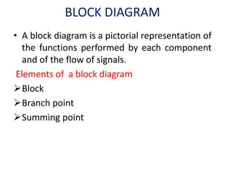
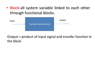
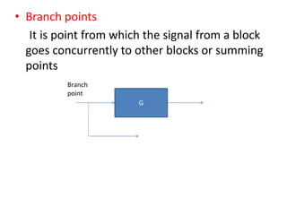
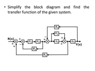
The document provides a comprehensive overview of block diagrams and signal flow graphs used in control engineering, detailing their components and reduction rules. It discusses how to construct and analyze these diagrams to find transfer functions, including Mason's gain formula and various pathways for signal flow. Additionally, it outlines procedures for converting block diagrams into signal flow graphs, emphasizing the importance of proper node representation and gain marking.


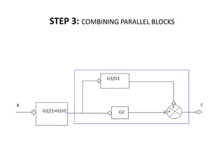
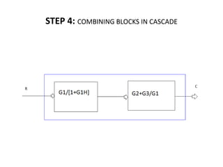
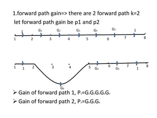
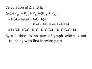
![(C/R)=[G1/(1+G1H)][G2+(G3/G1)]
=[G1/(1+G1H)][(G1G2+G3)/G1]
=[(G1G2+G3)/(1+G1H)]](https://image.slidesharecdn.com/blockdiarules-240504004352-0fb1ffcb/85/Block-diagram-reduction-techniques-in-control-systems-ppt-23-320.jpg)
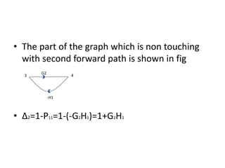
![RESULT
THE OVER ALL TRANSFER FUNCTION OF THE SYSTEM,
(C/R)=[(G1G2+G3)/(1+G1H)]](https://image.slidesharecdn.com/blockdiarules-240504004352-0fb1ffcb/85/Block-diagram-reduction-techniques-in-control-systems-ppt-24-320.jpg)
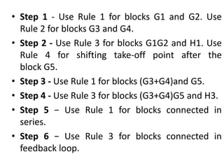
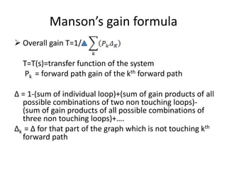
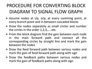
![Transfer function, T
by Mason’s gain formula the TF,
T=1/Δ
= 1/Δ(P1Δ1+P2Δ2) (K=2, we have 2
forward paths)
T=[G1G2G3G4G5+G4G5G6(1+G2H1)]/
[1+G2H1+G2G3H2+G5H3+G2G5H1H3+G2
G3G5H2H3]](https://image.slidesharecdn.com/blockdiarules-240504004352-0fb1ffcb/85/Block-diagram-reduction-techniques-in-control-systems-ppt-42-320.jpg)


![[Deck] What's New in Spark-Iceberg Integration via DSV2.pptx](https://cdn.slidesharecdn.com/ss_thumbnails/deckwhatsnewinspark-icebergintegrationviadsv2-260210005337-25955b12-thumbnail.jpg?width=640&height=640&fit=bounds)


