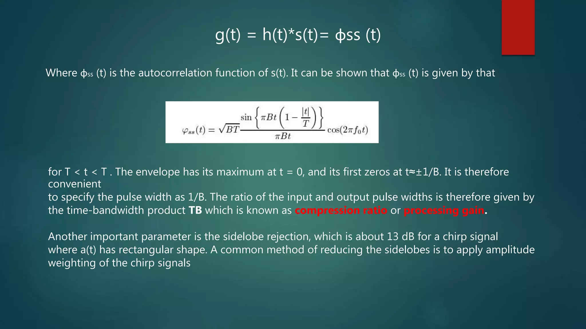
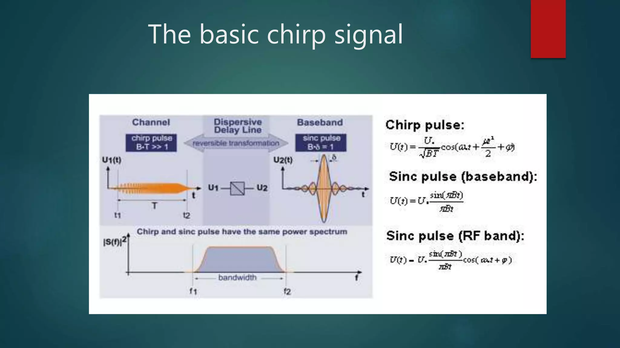
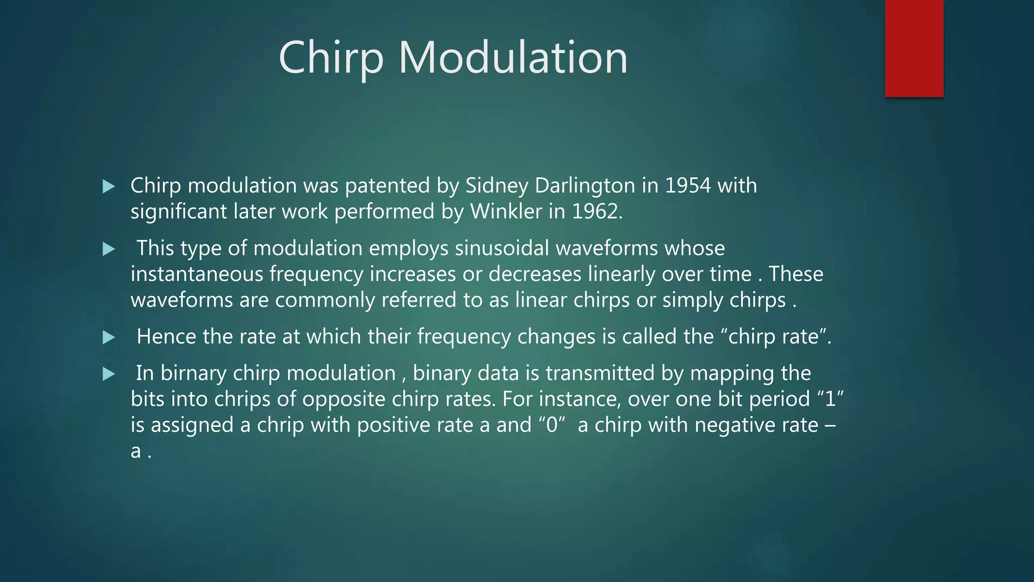
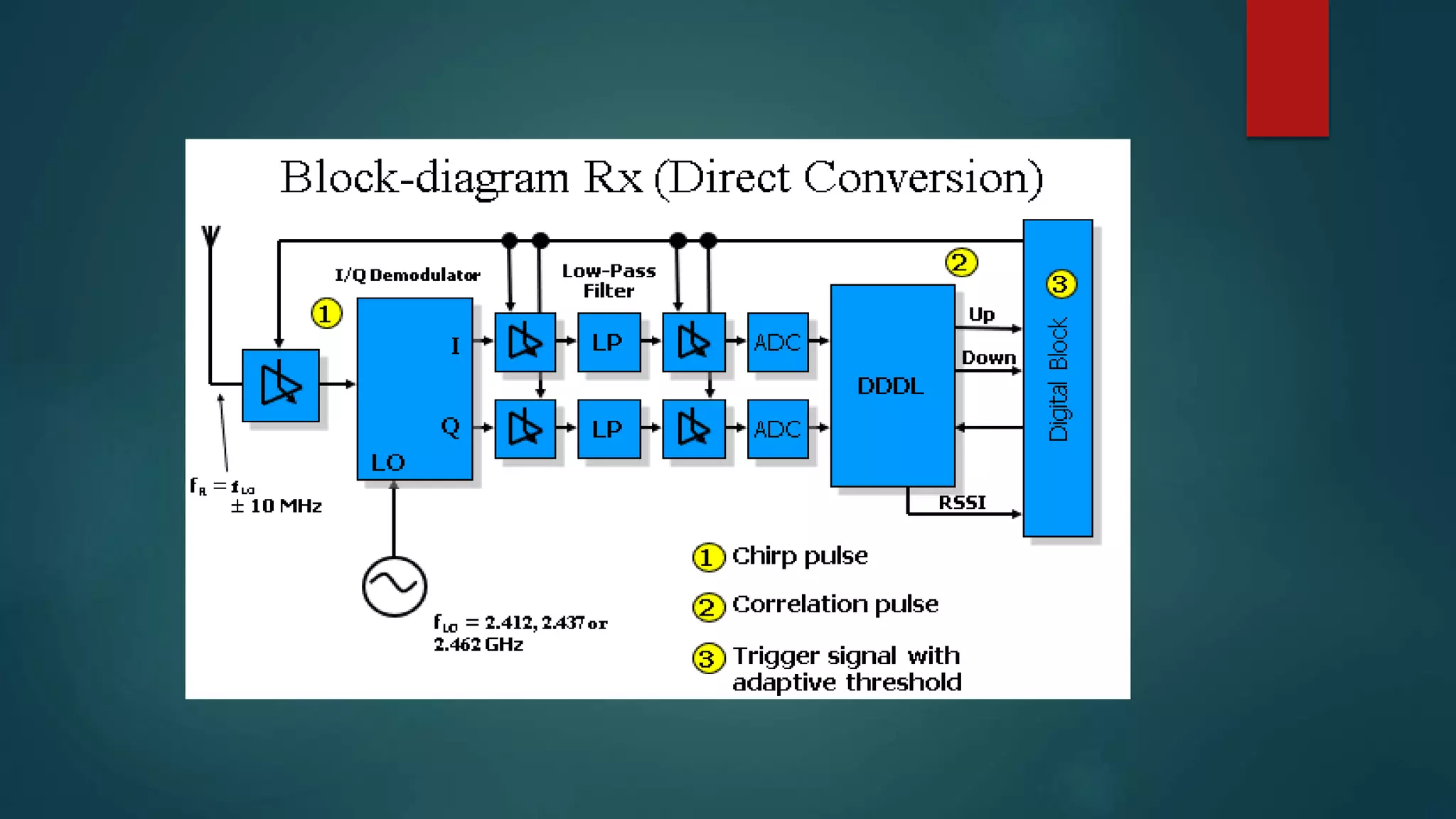
This document discusses Chirp Spread Spectrum (CSS) communication. It defines key terms like spectrum, spread spectrum, and chirps. It explains that chirps are signals where frequency increases or decreases over time. CSS uses chirp signals that are spread over a wide bandwidth for communication. It provides several benefits - high robustness against interference due to its wide bandwidth, resistance to multipath fading and Doppler shift, low power consumption, and low latency.
![A chirp signal waveform can be written as
S(t) = a(t) cos[θ(t)]
Where θ(t) is the phase and a(t) is the envelope of the chirp signal which is zero outside a
time interval of length T.
The instantaneous frequency is defined as
fM (t) =
1
2𝜋
𝑑θ
𝑑𝑡
The chirp rate is defined by
µ(t) =
𝑑fM
𝑑𝑡
=
1
2𝜋
𝑑2θ
𝑑𝑡2
and represents the rate of change of the instantaneous frequency.
Chirp(conc.)](https://image.slidesharecdn.com/chirpspreadspectrumcommunication-200401093125/75/Chirp-spread-spectrum-communication-6-2048.jpg)
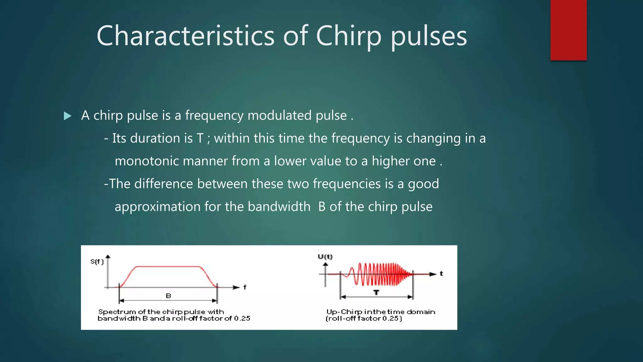
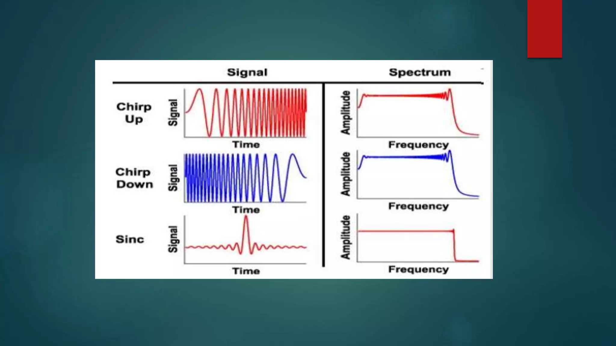
![ When µ (t) > 0 then the signal is called up-chirps
When µ (t) < 0 then the signal is called down-chirps
For a linear chirp µ (t) is constant, and hence fM (t) is a linear
function of t, and θ(t) is a quadratic function those with.
If we take the waveform to be centered at t = 0 it can be written as
s(t) = a(t) cos [2𝜋f0t + 𝜋µ𝑡2
+ φ0 ]
where fc is the center frequency and a(t) = 0 for |t| > T/2
It is convenient to define the bandwidth B as the range of the instantaneous
frequency, so that
B =| µ |T
Chirp(conc.)](https://image.slidesharecdn.com/chirpspreadspectrumcommunication-200401093125/75/Chirp-spread-spectrum-communication-7-2048.jpg)