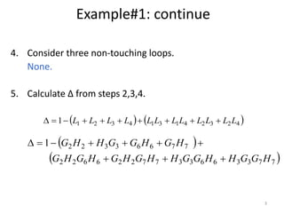
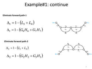
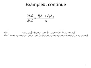
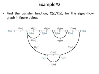
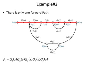
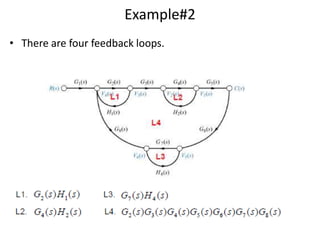
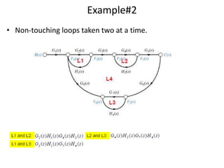
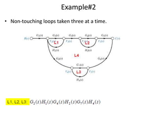
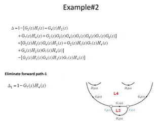
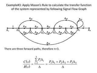
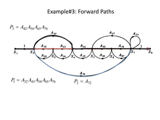
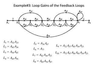
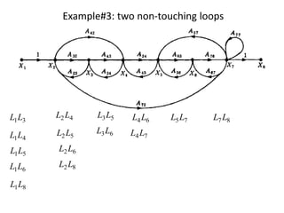
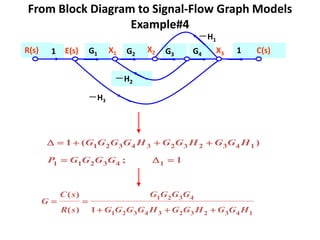
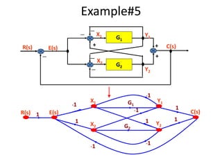
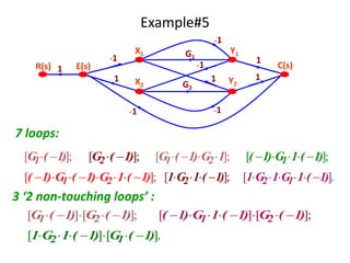
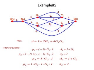
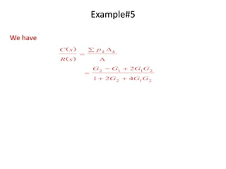
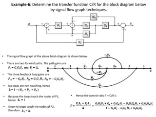
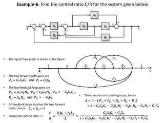
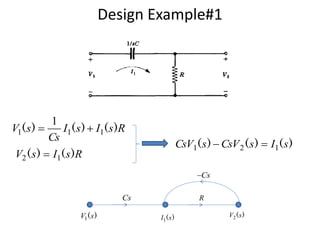
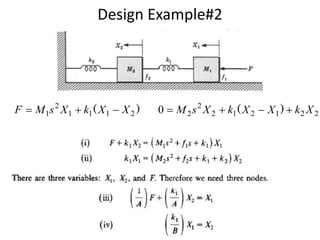
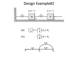
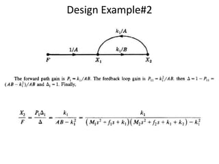
This document contains several examples of using Mason's Rule to calculate transfer functions from signal flow graphs. The examples demonstrate applying Mason's Rule to calculate loop gains, forward path gains, non-touching loops, and the overall transfer function. Signal flow graphs are constructed from block diagrams and the steps of Mason's Rule are systematically worked through.
2. 2
Example#1: Apply Mason’s Rule to calculate the transfer function
of the system represented by following Signal Flow Graph
774663332221 HGLHGLGHLHGL ,,,
2. Calculate all loop gains.
3. Consider two non-touching loops.
L1L3 L1L4
L2L4 L2L3
2)(pathand1)(path 8765243211 GGGGPGGGGP
1. Calculate forward path gains for each forward path.
P1
P2
12. Example#3: Apply Mason’s Rule to calculate the transfer function
of the system represented by following Signal Flow Graph
332211
3
1 PPP
P
sR
sC i
ii
)(
)(
There are three forward paths, therefore n=3.
23. Example-6: Determine the transfer function C/R for the block diagram below
by signal flow graph techniques.
• The signal flow graph of the above block diagram is shown below.
• There are two forward paths. The path gains are
• The three feedback loop gains are
• No loops are non-touching, hence
• Since no loops touch the nodes of P2,
therefore
• Because the loops touch the nodes of P1,
hence
• Hence the control ratio T = C/R is
24. Example-6: Find the control ratio C/R for the system given below.
• The two forward path gains are
• The signal flow graph is shown in the figure.
• The five feedback loop gains are
• Hence the control ratio T =
• There are no non-touching loops, hence
• All feedback loops touches the two forward
paths, hence