Download as PDF, PPTX
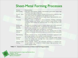
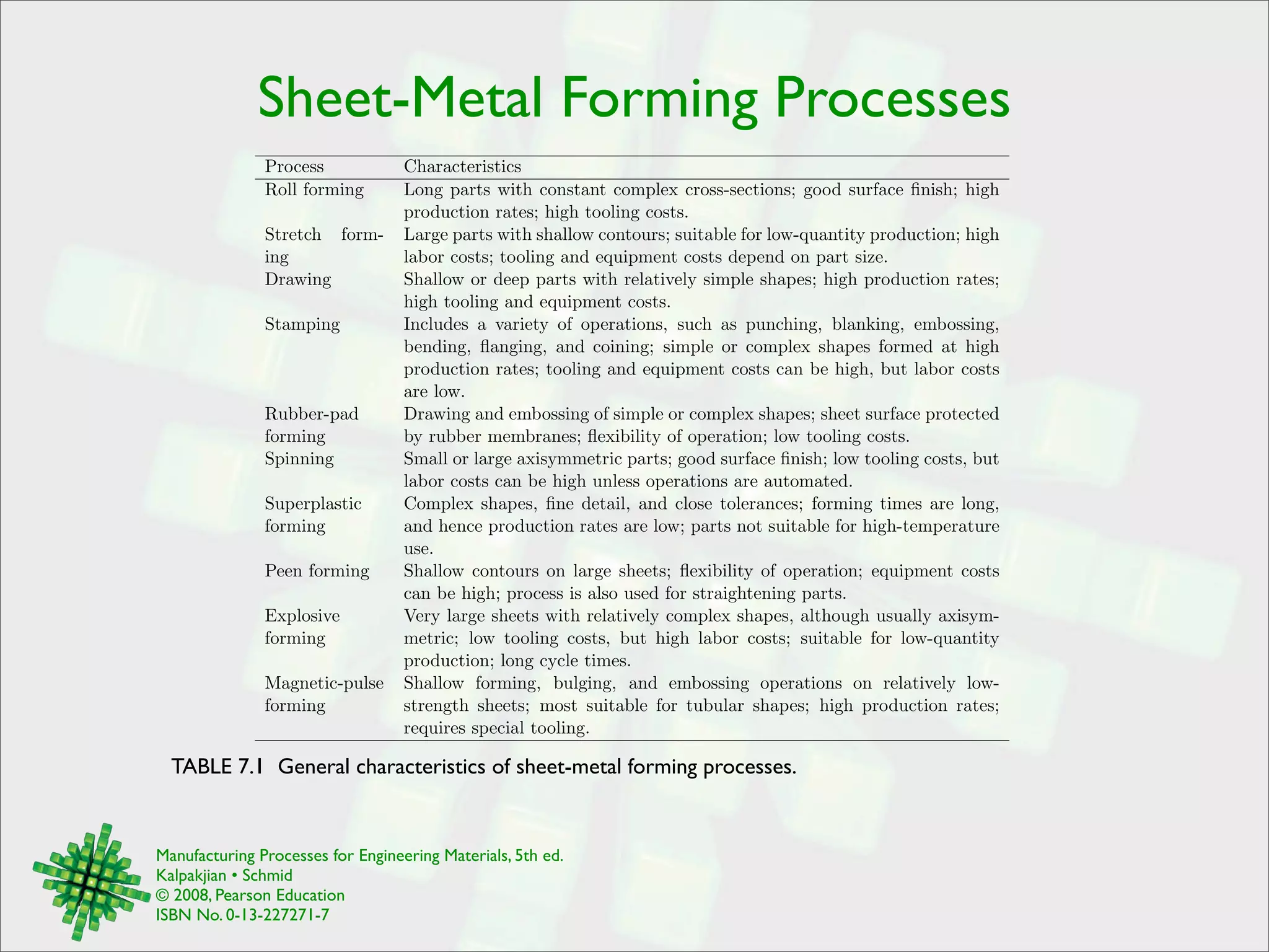

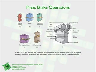
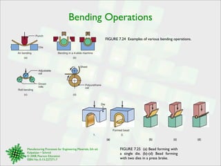
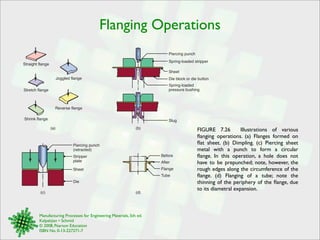
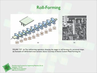


The document describes various sheet metal forming processes and provides characteristics of each. It discusses roll forming for parts with complex cross-sections and high production rates but high tooling costs. Stretch forming is described as suitable for low quantity production but with high labor costs and tooling/equipment costs depending on part size. Drawing is outlined as having high production rates but also high tooling and equipment costs.