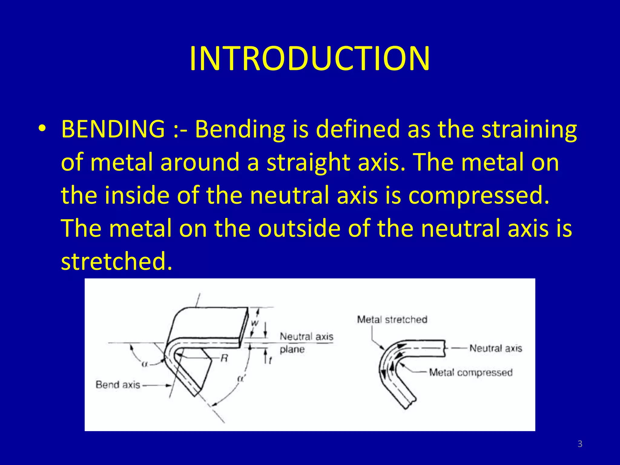
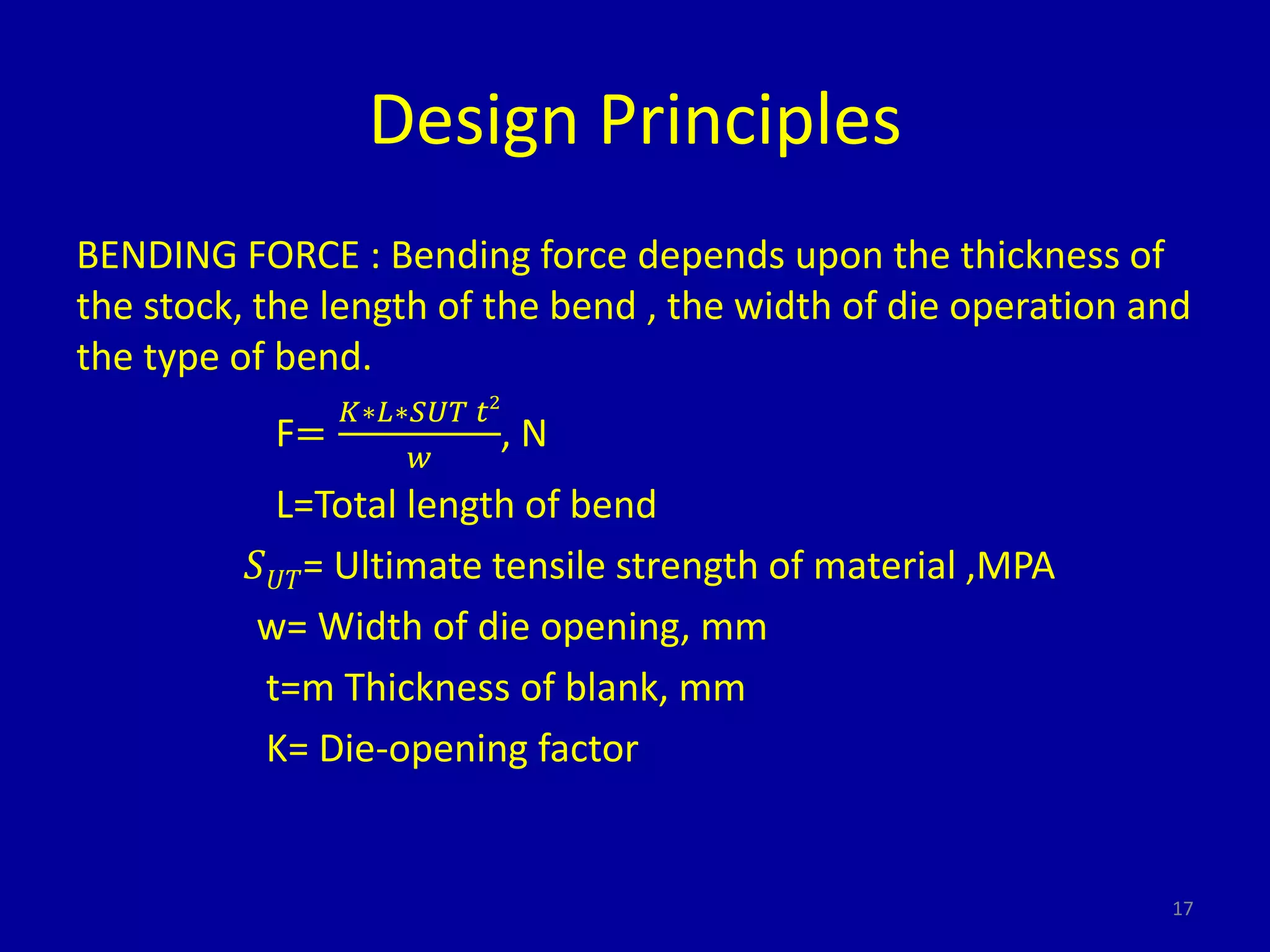
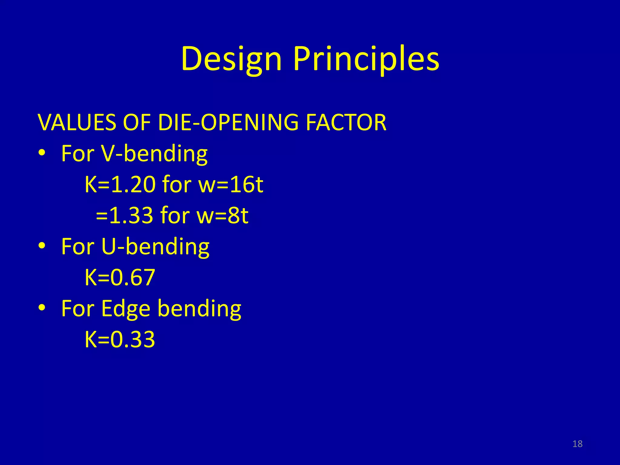
This document provides information on bending theory and design principles for bending operations. It discusses the following key points in 3 sentences:
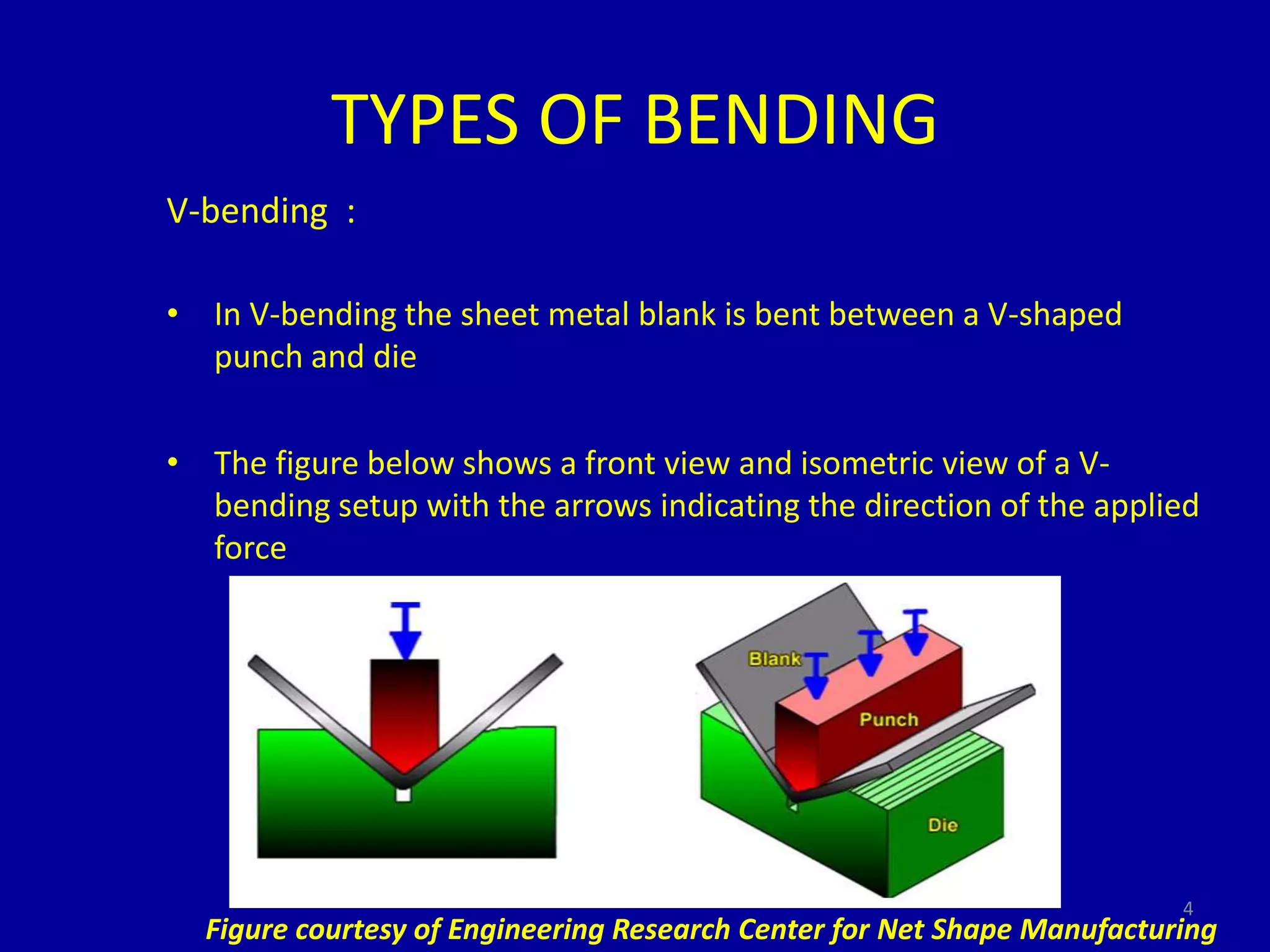
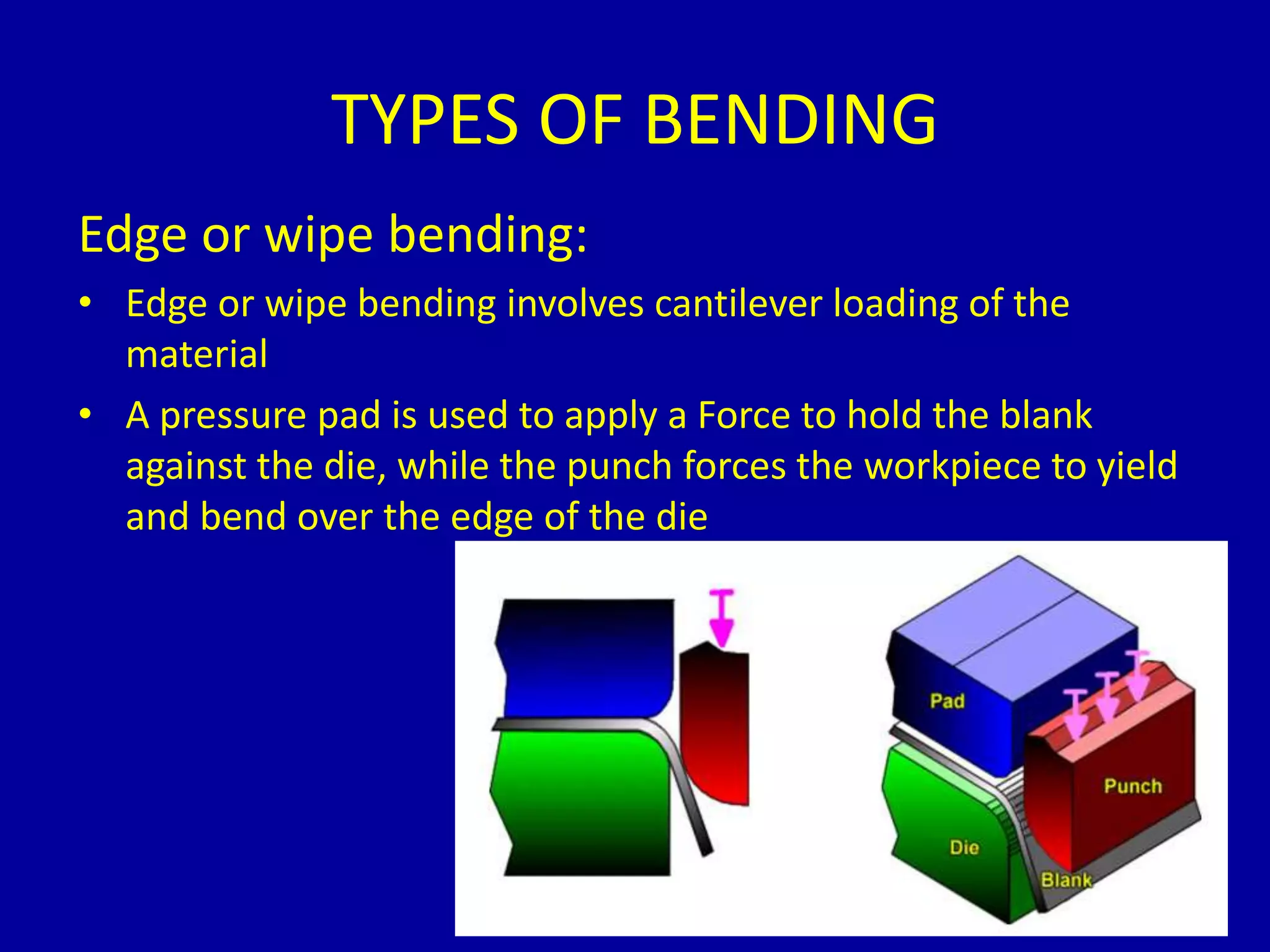
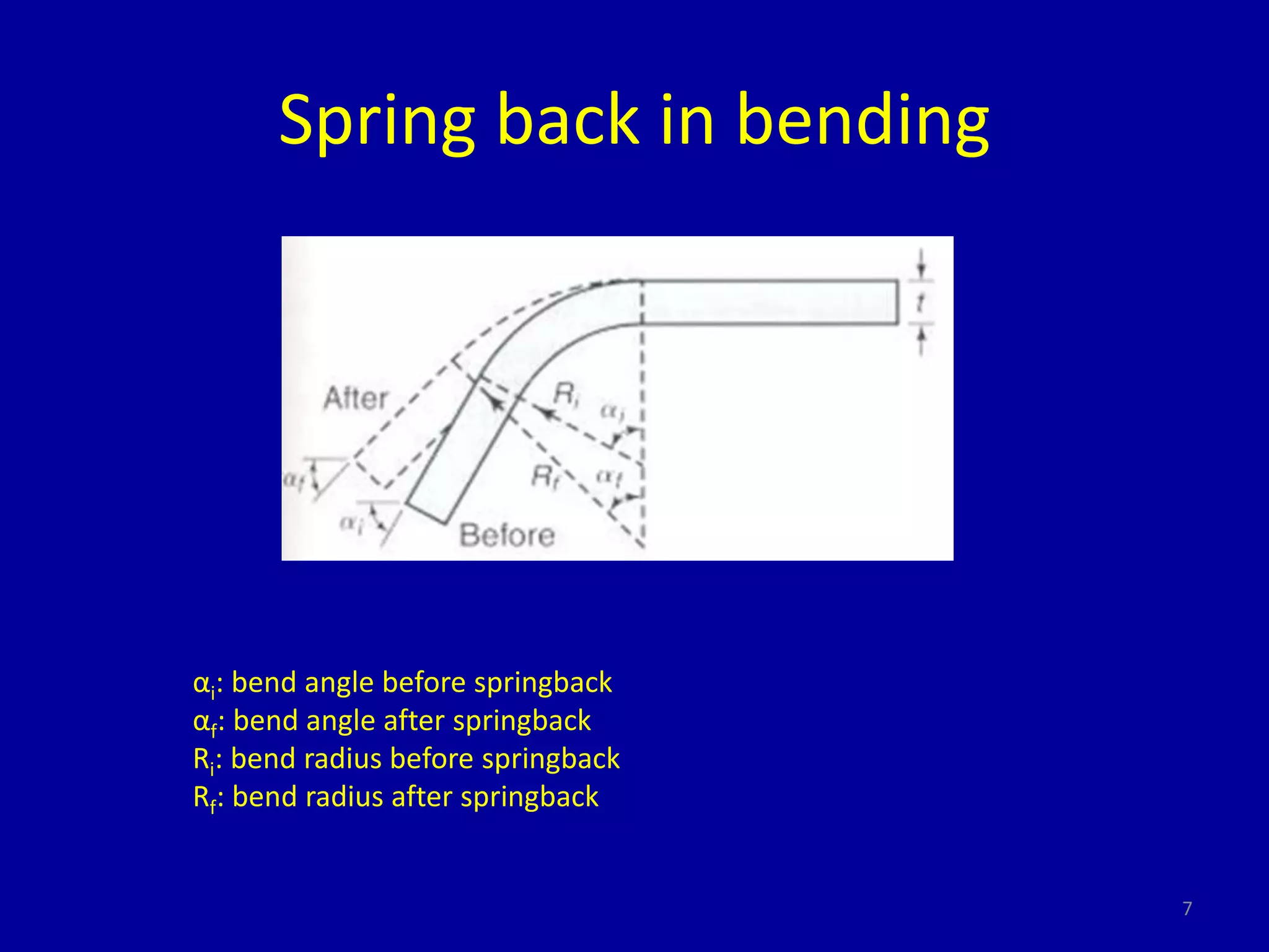
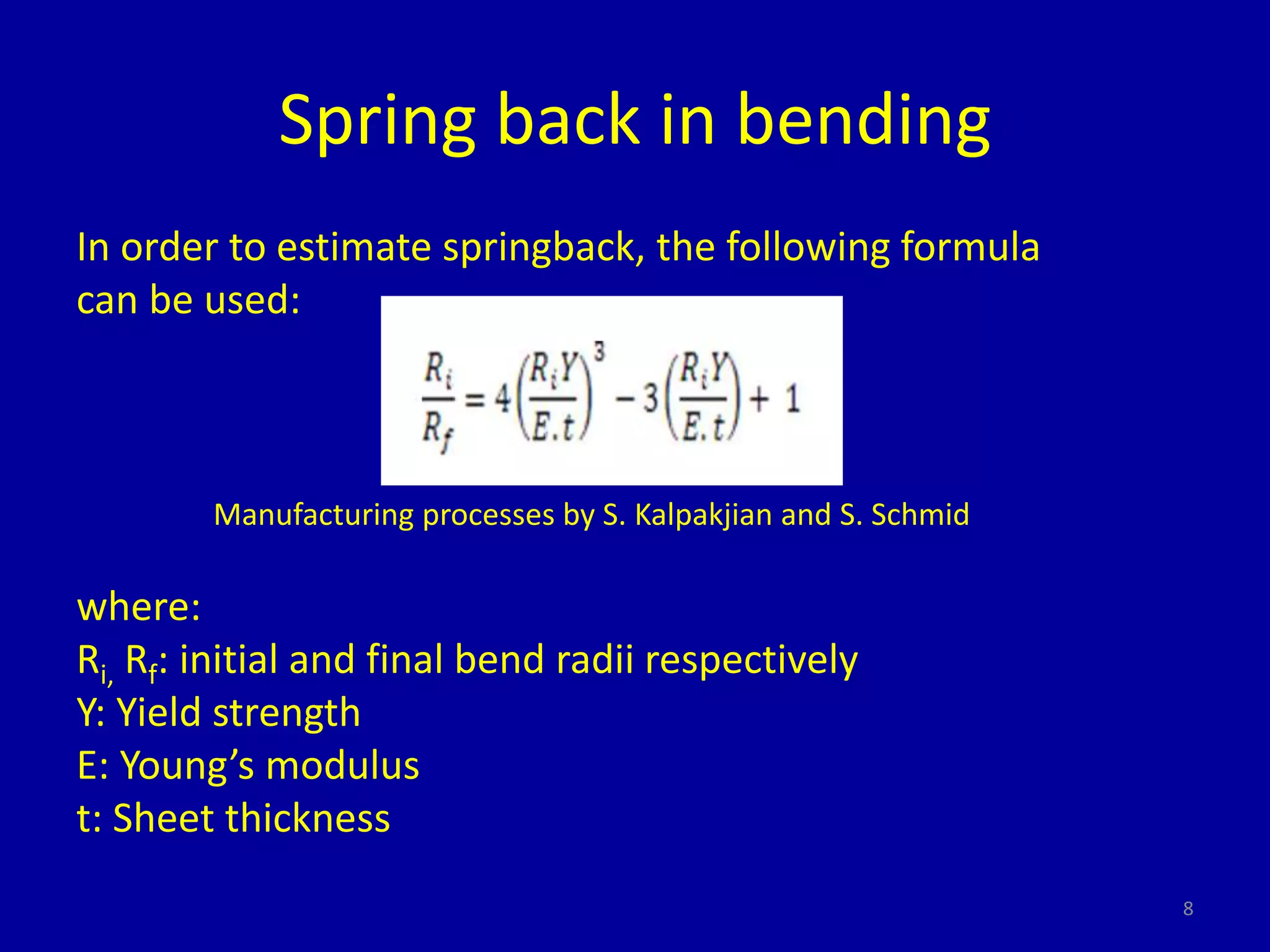
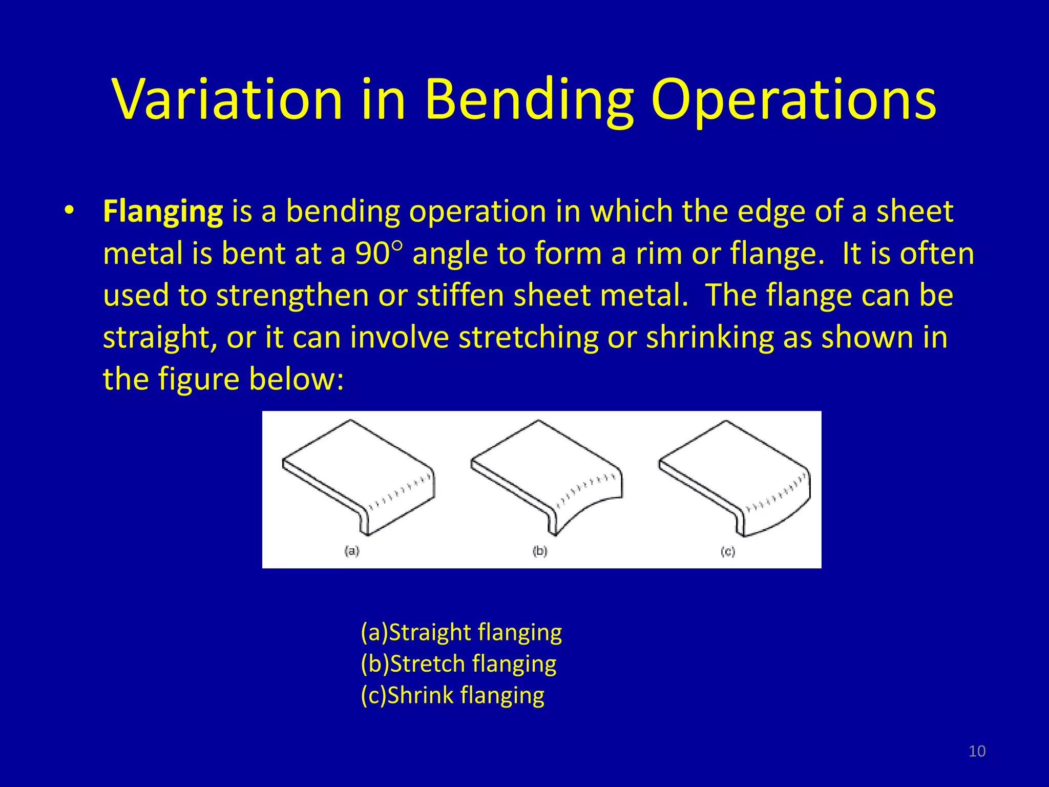
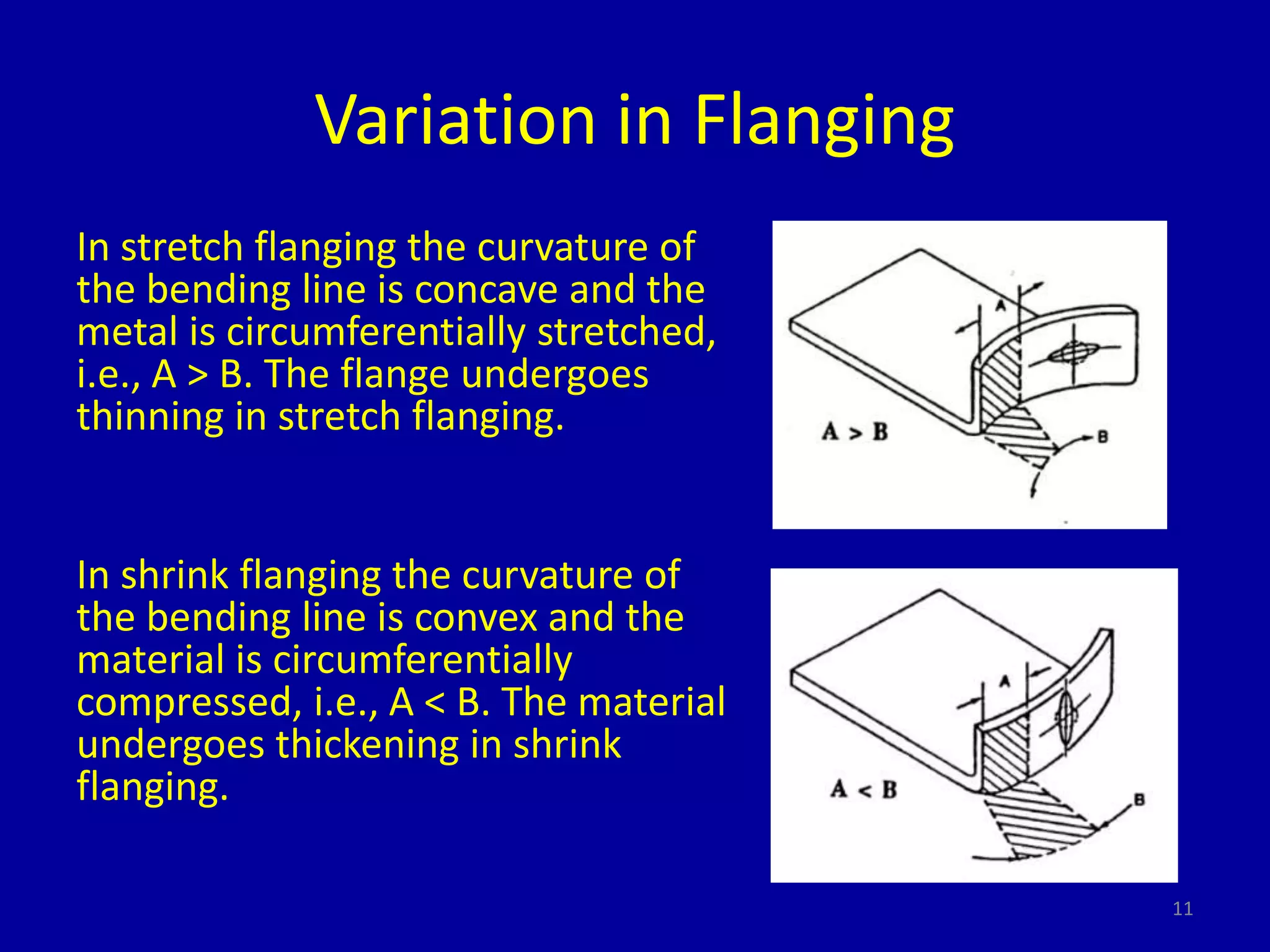
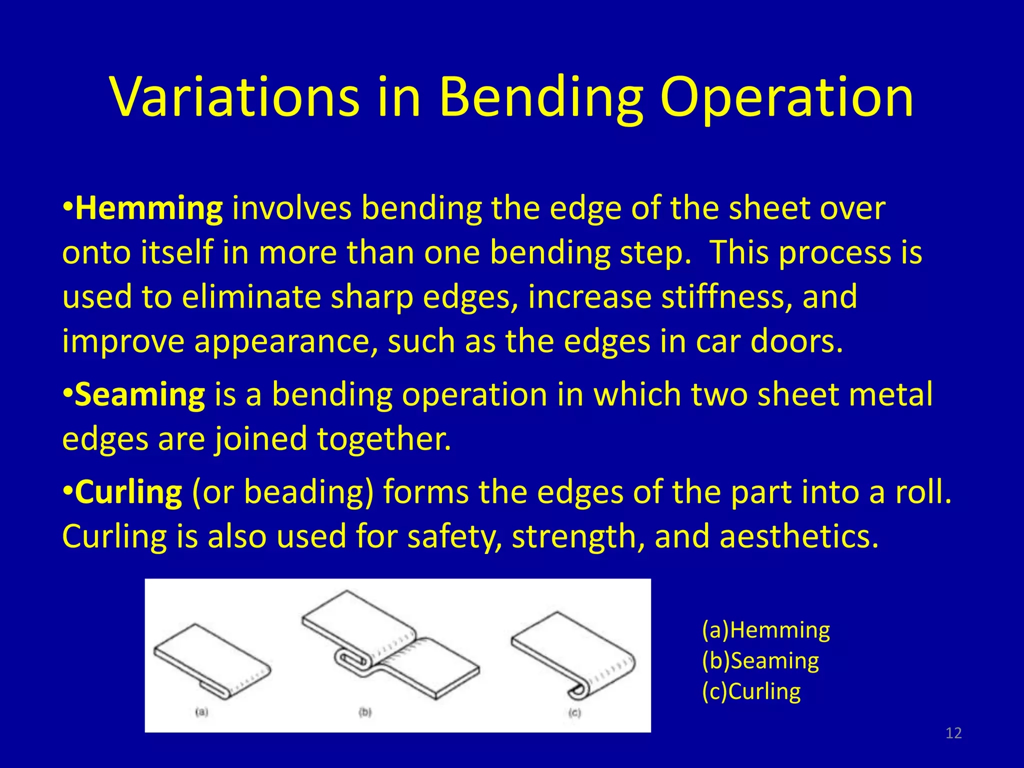
Types of bending covered include V-bending, edge bending, and flanging. Springback occurs as the bent part partially recovers its original shape after bending forces are removed. The document outlines methods to compensate for springback like overbending and bottoming, and provides formulas to estimate springback and calculate bending allowance and force.