Download as PDF, PPTX
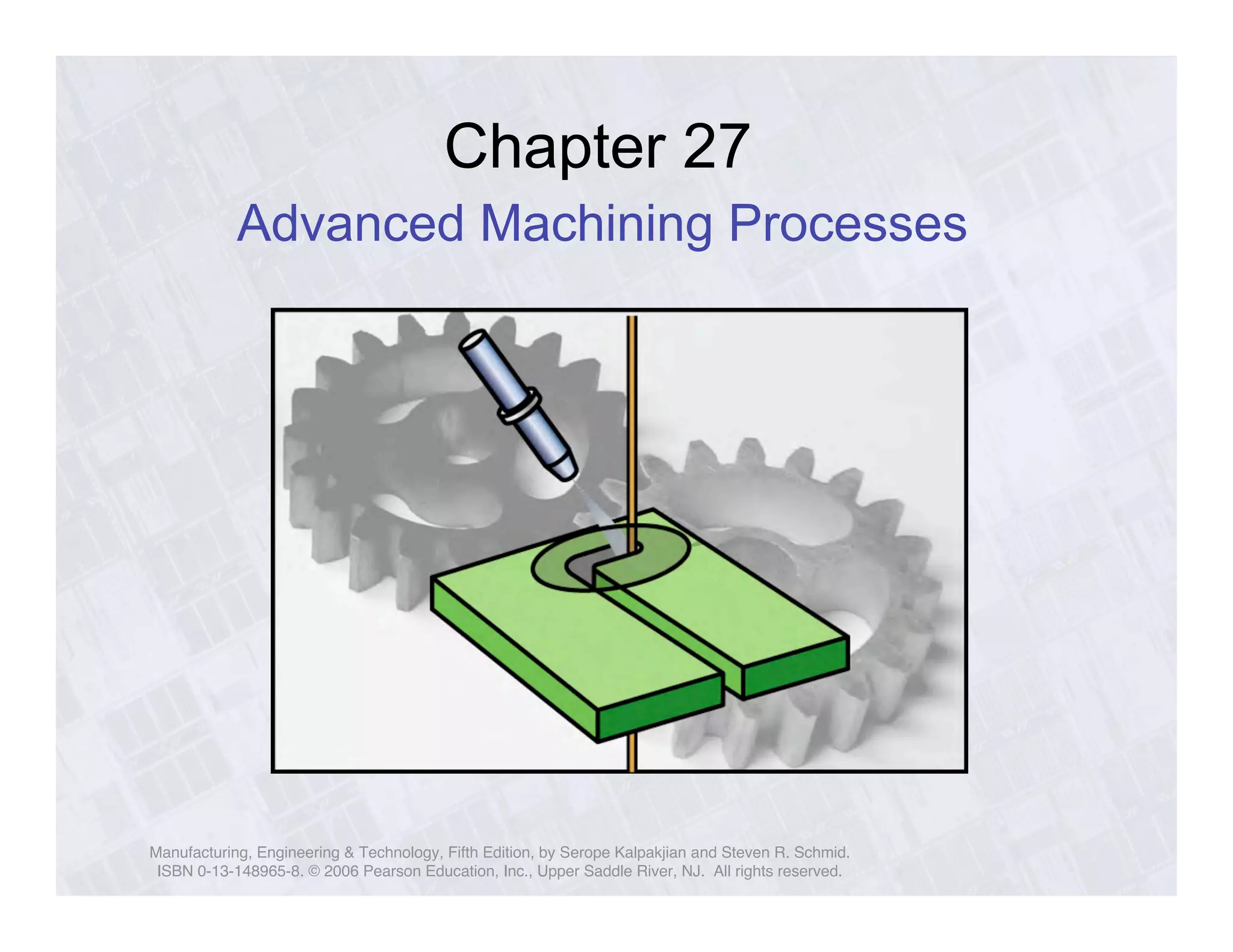
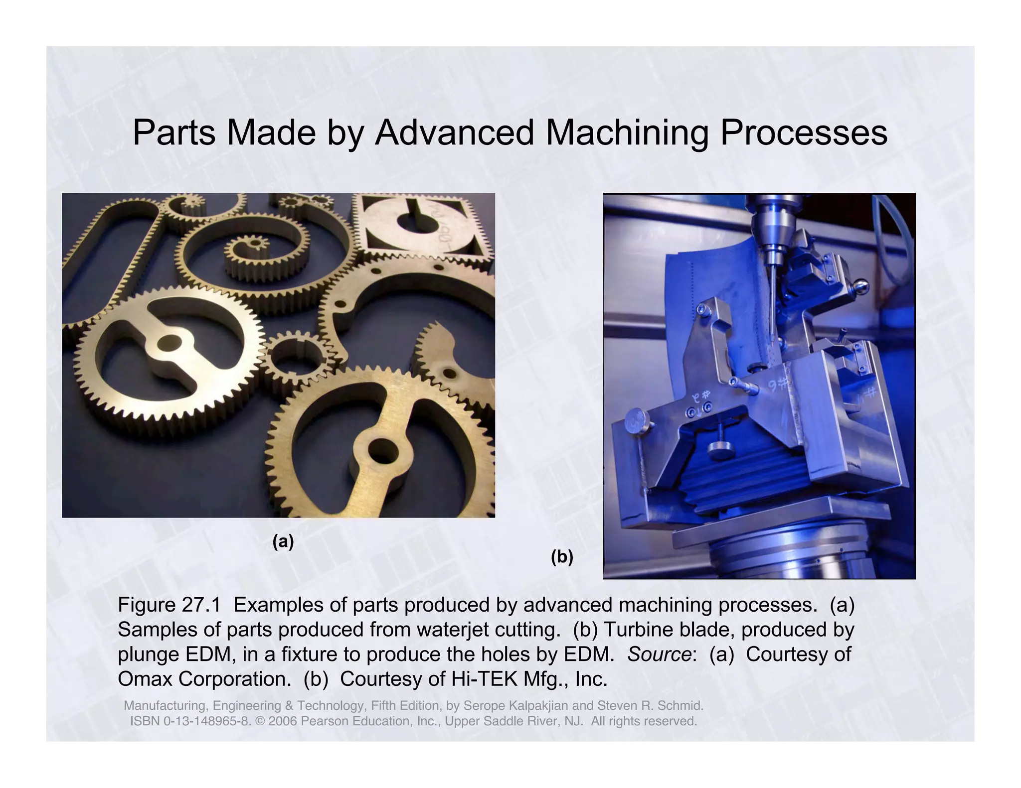
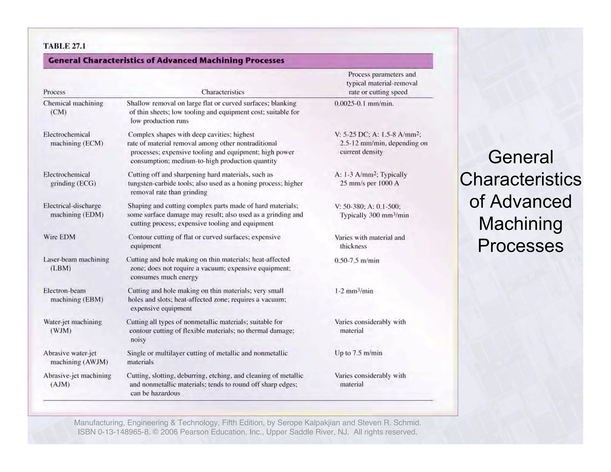
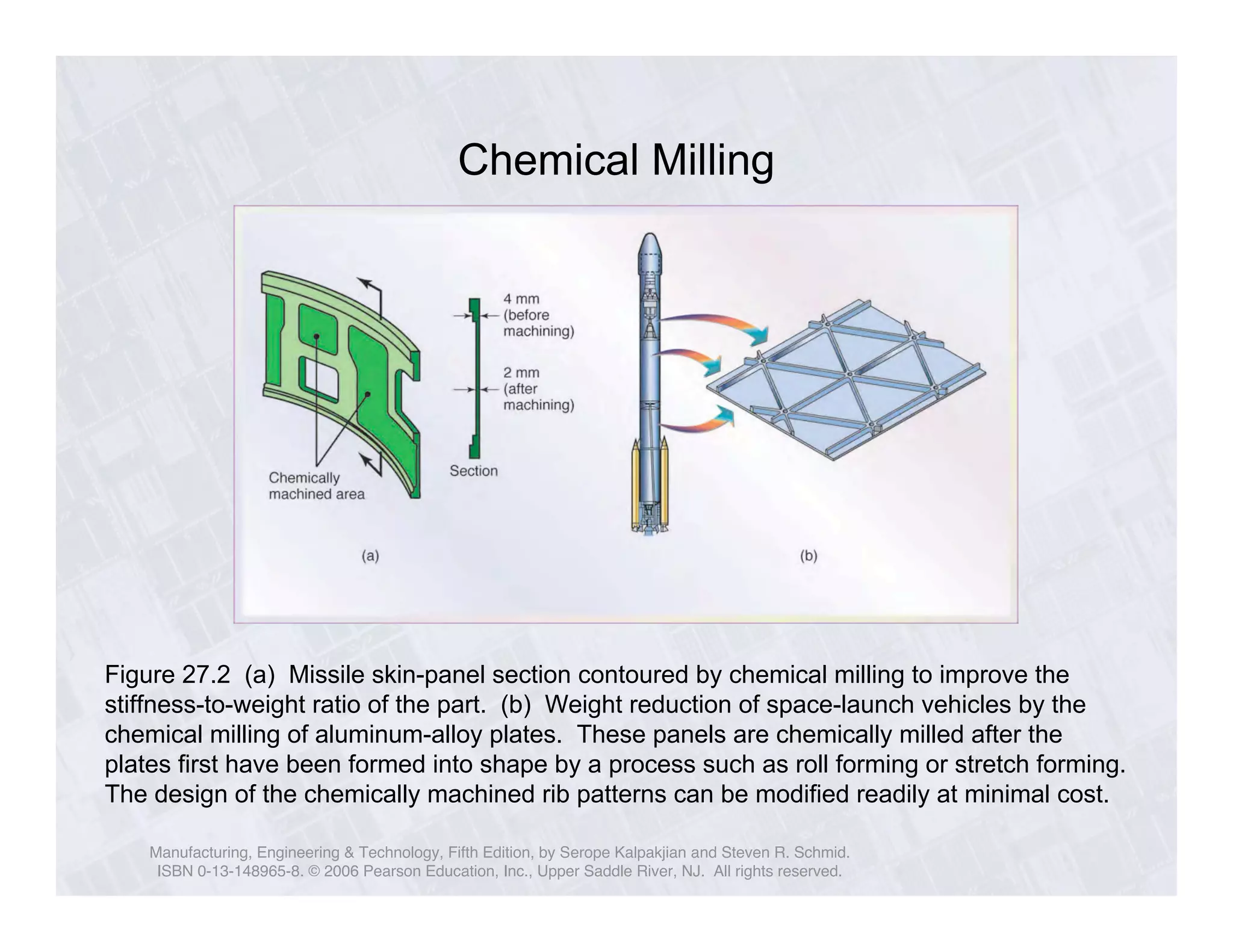
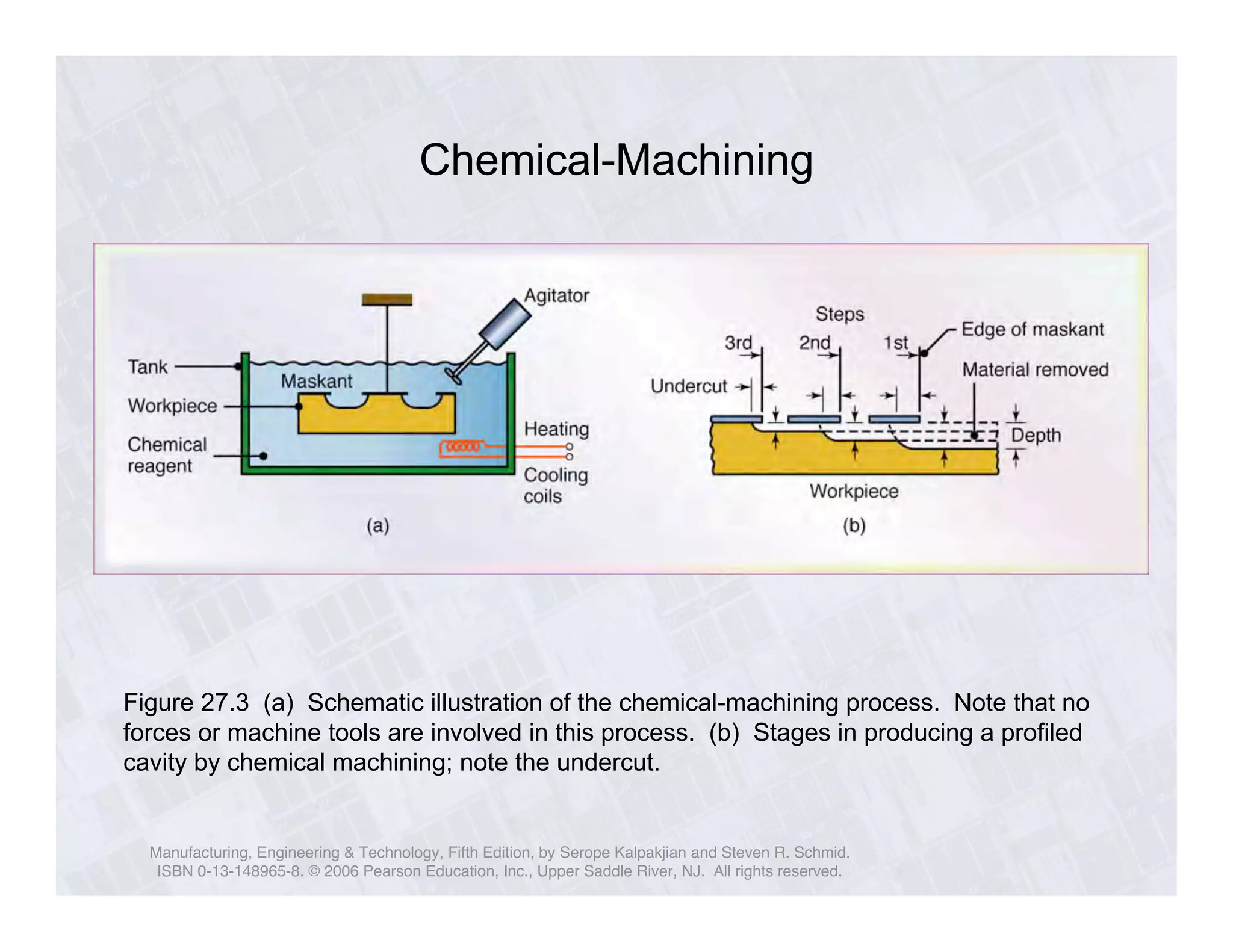
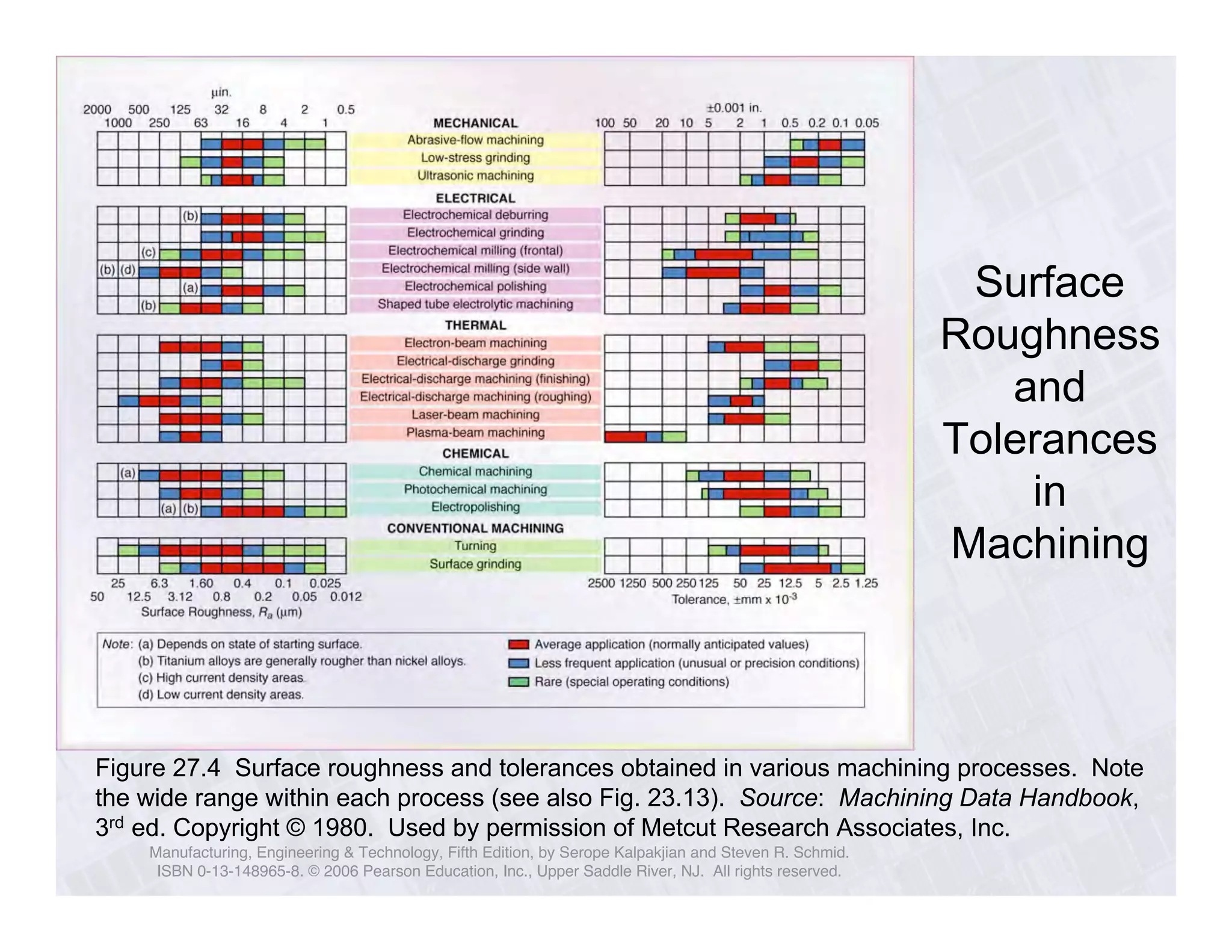
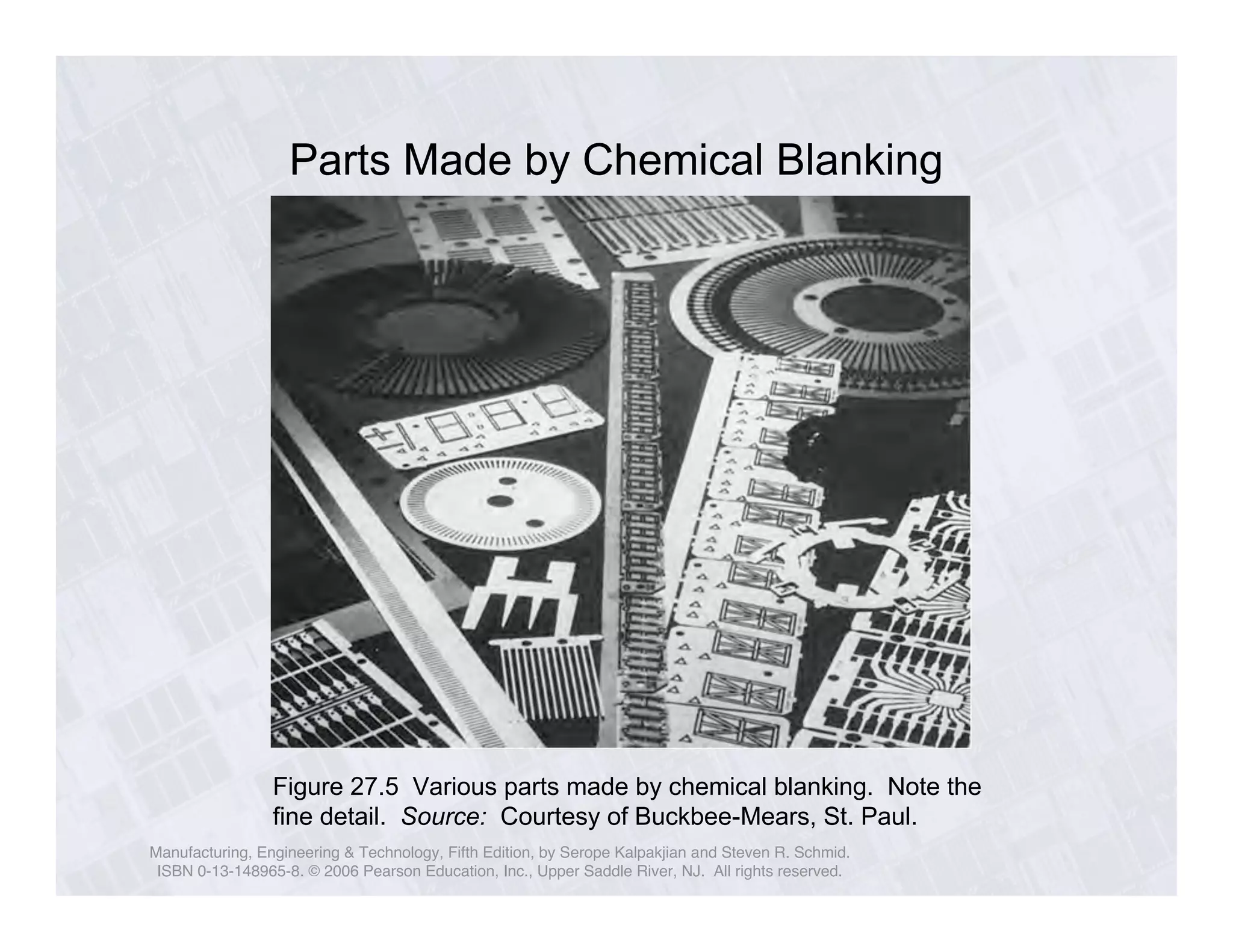
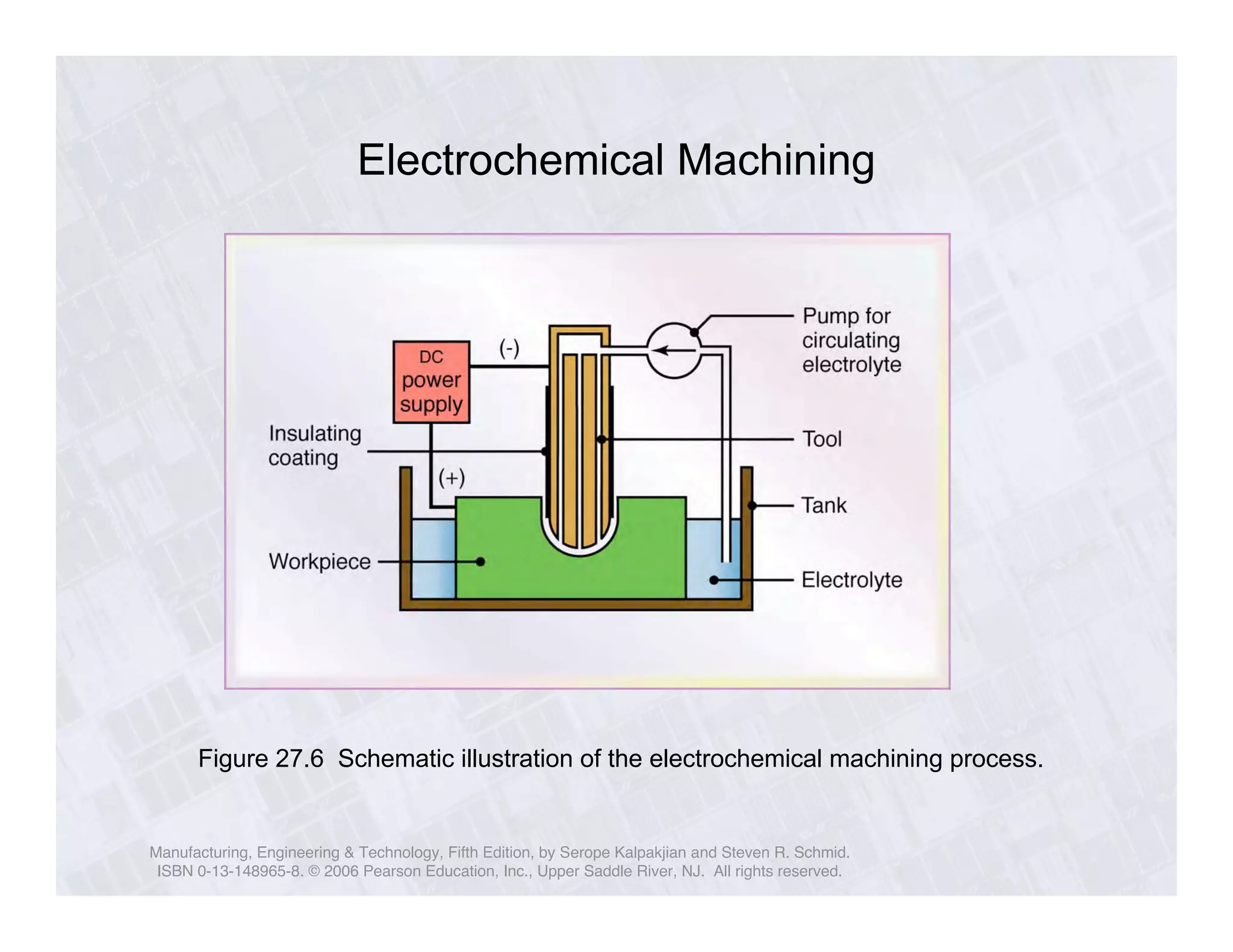
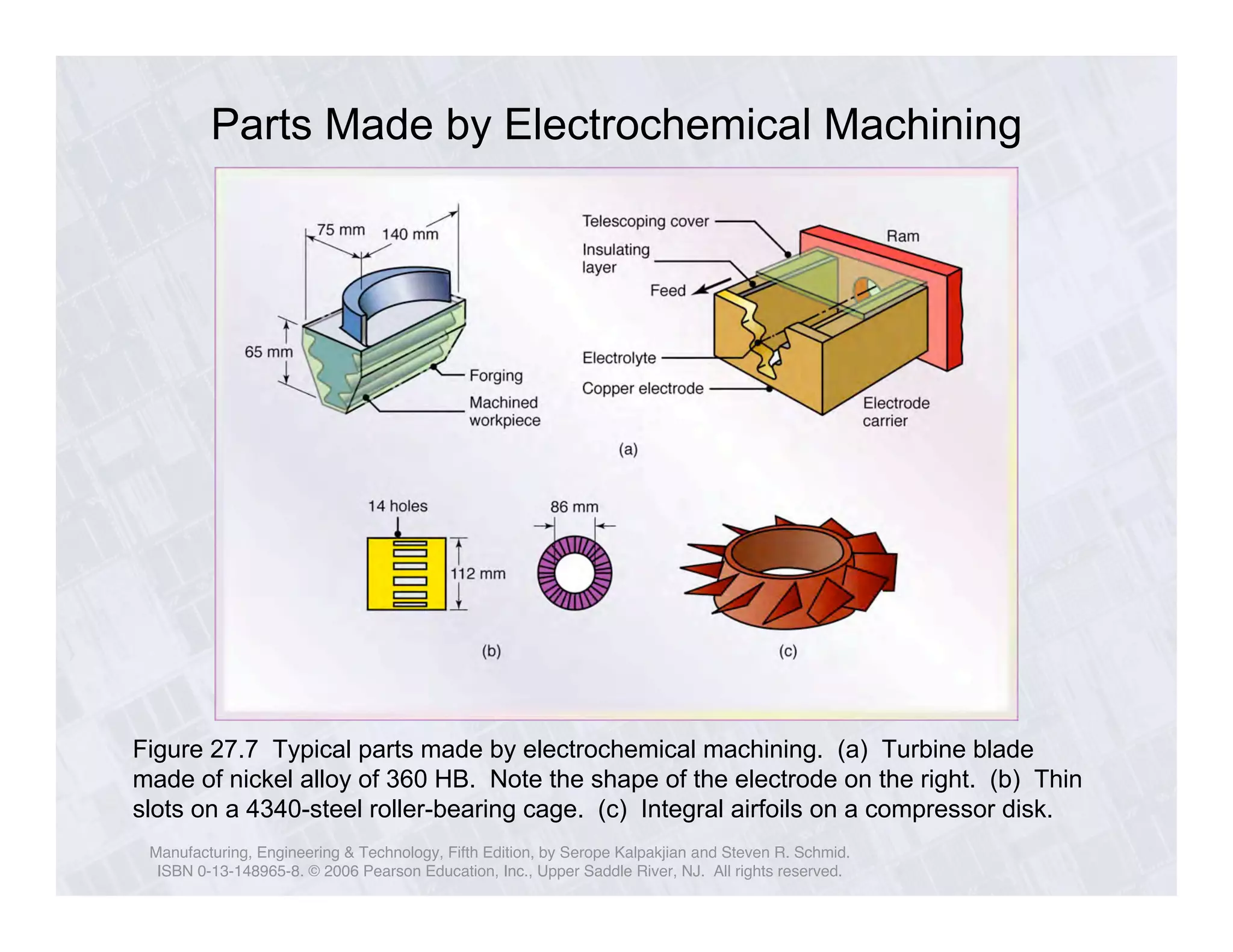
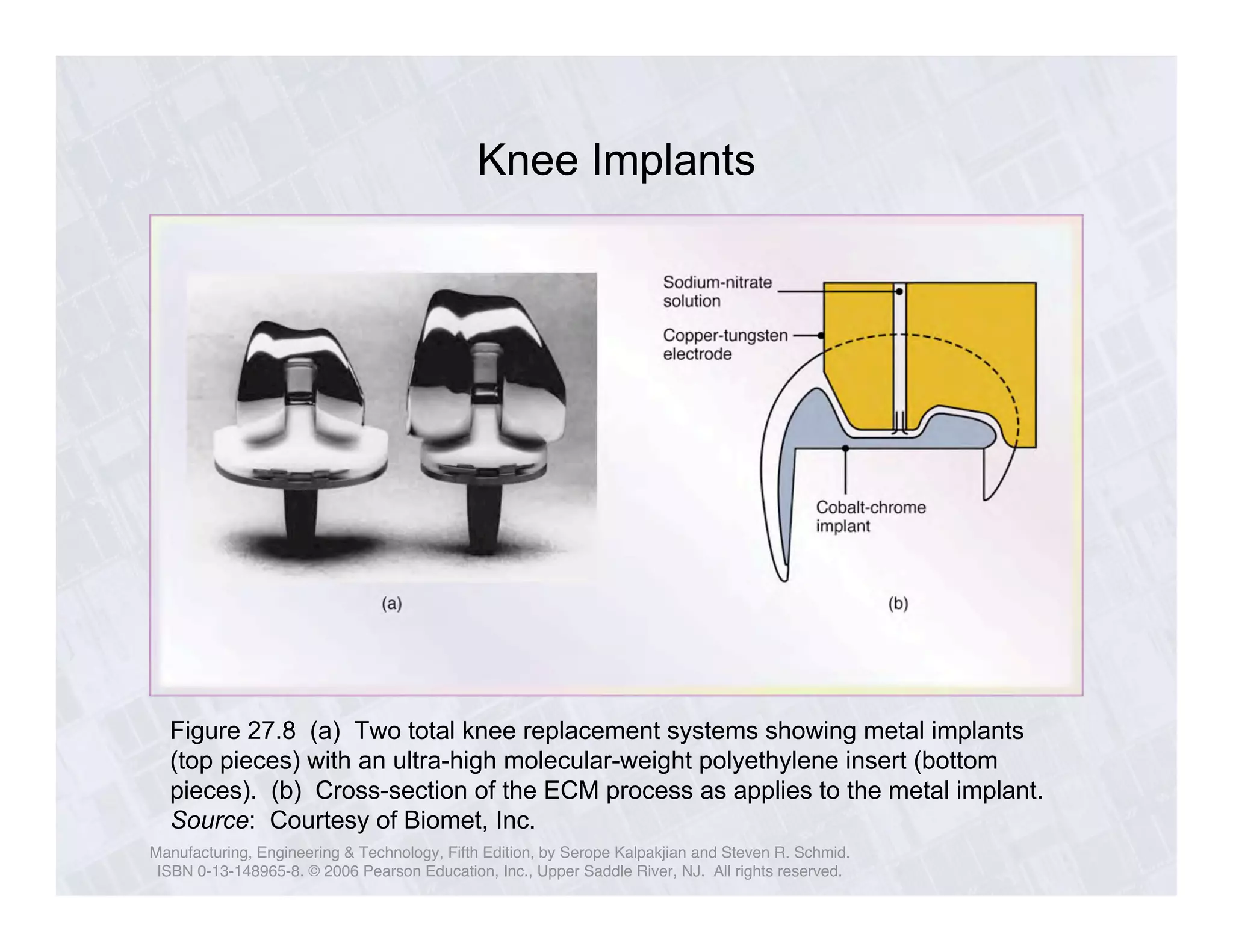
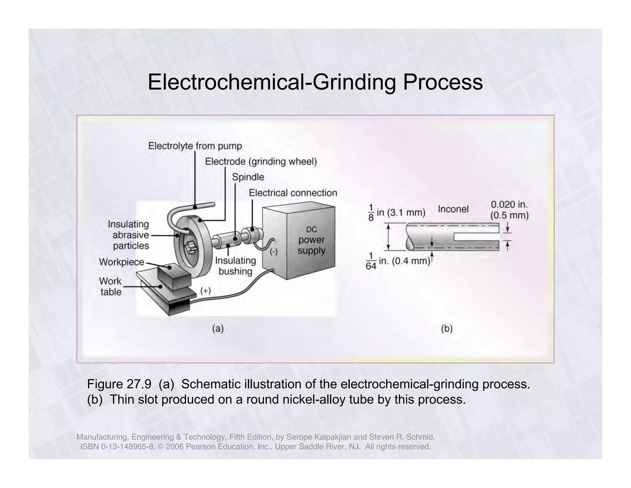
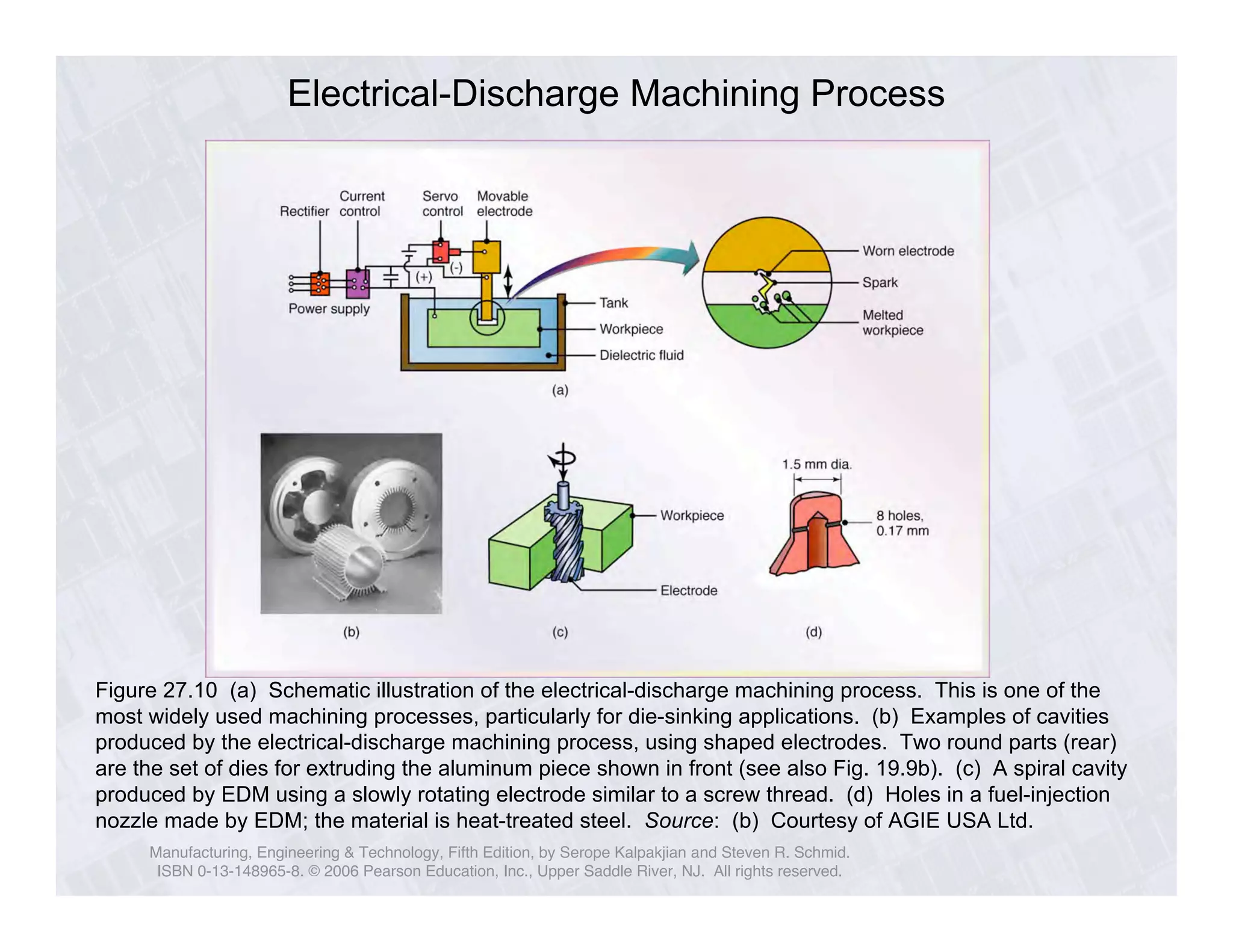
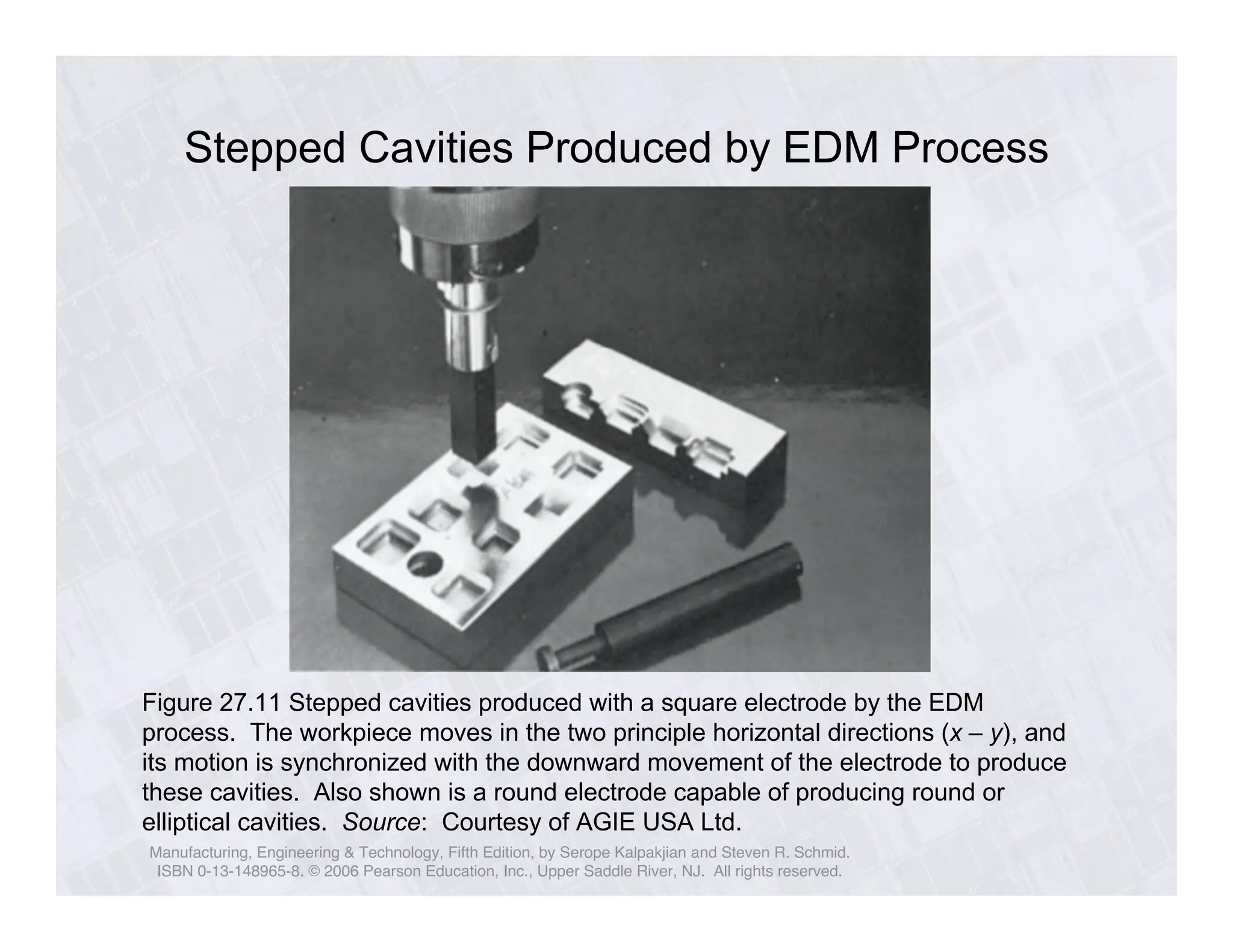
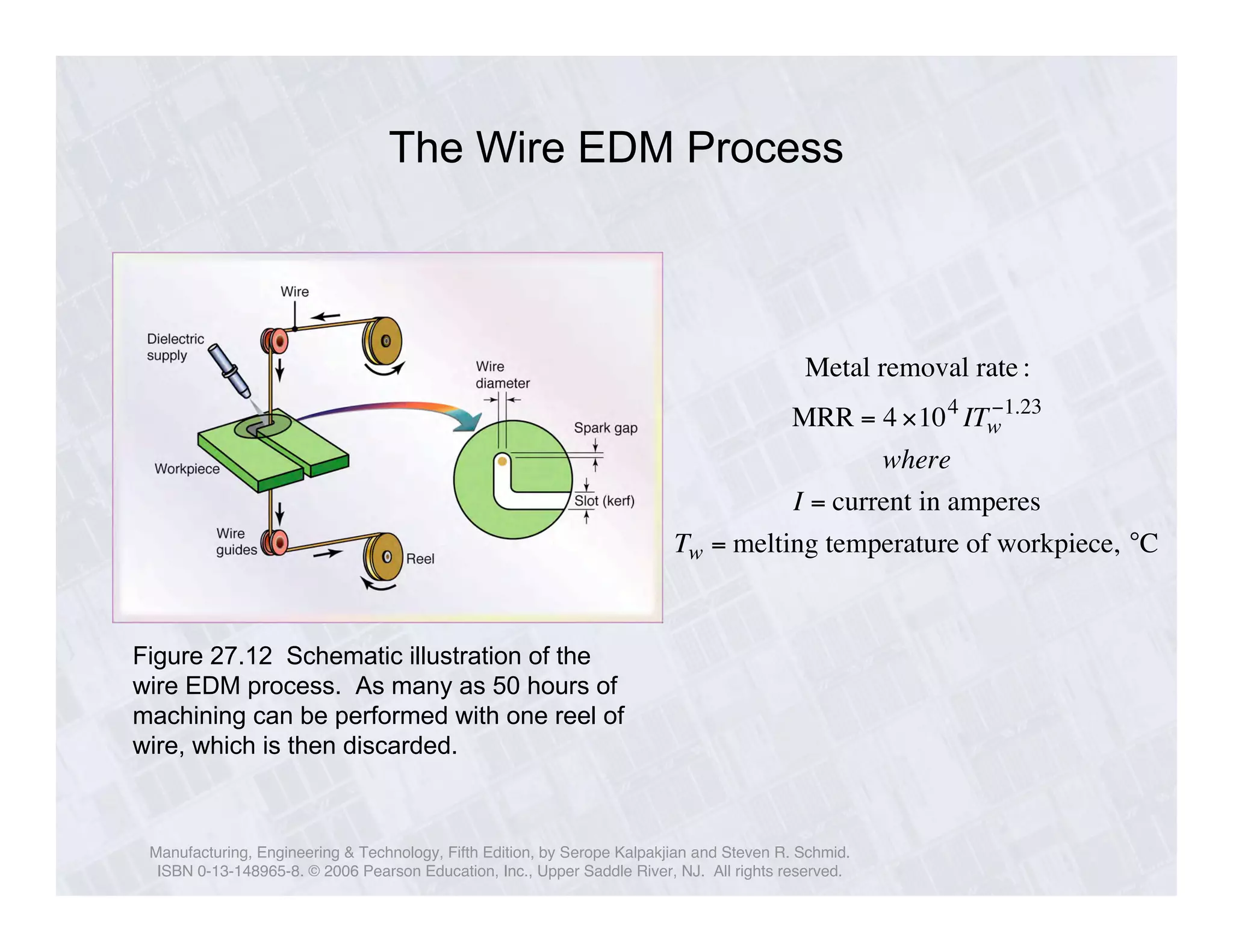
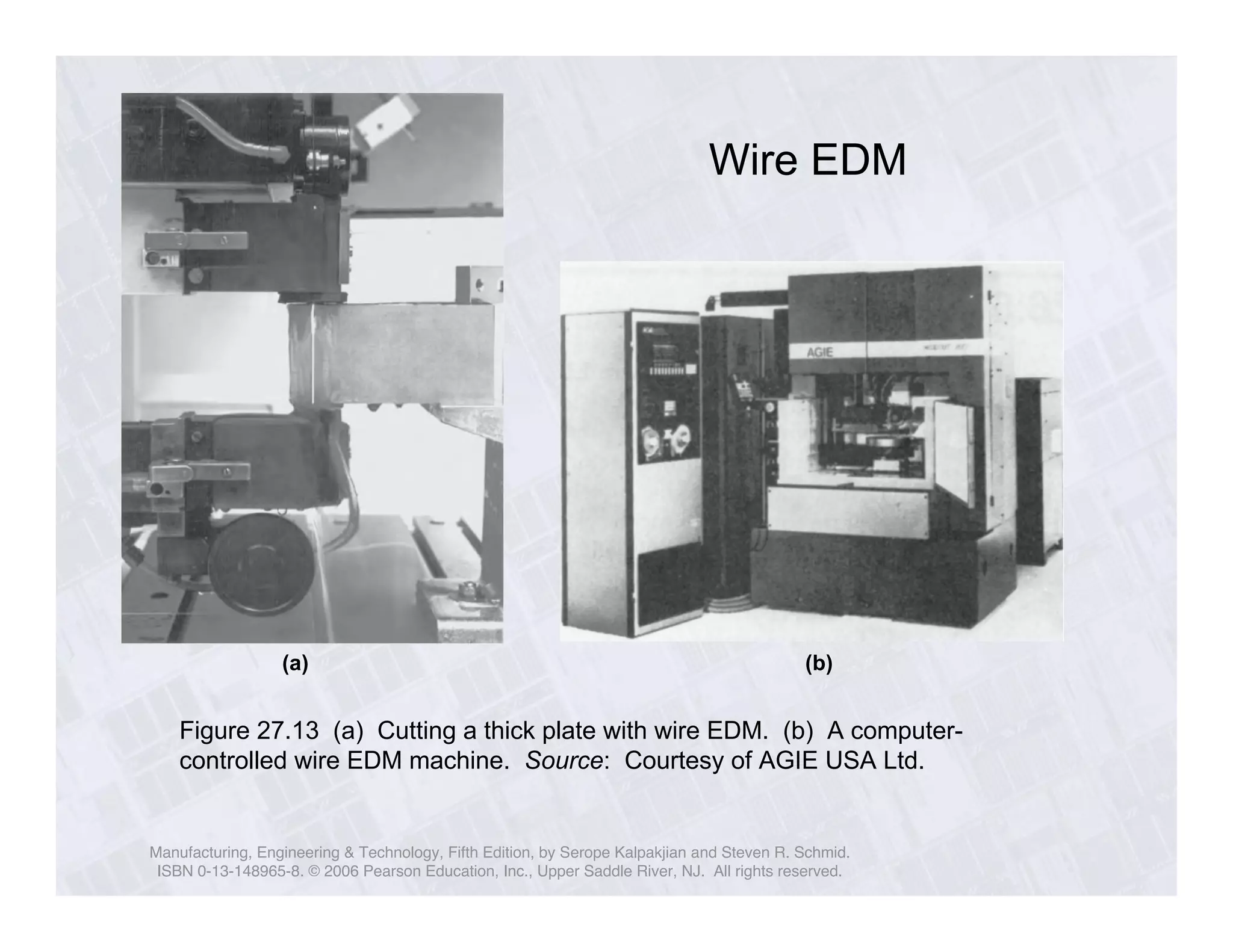
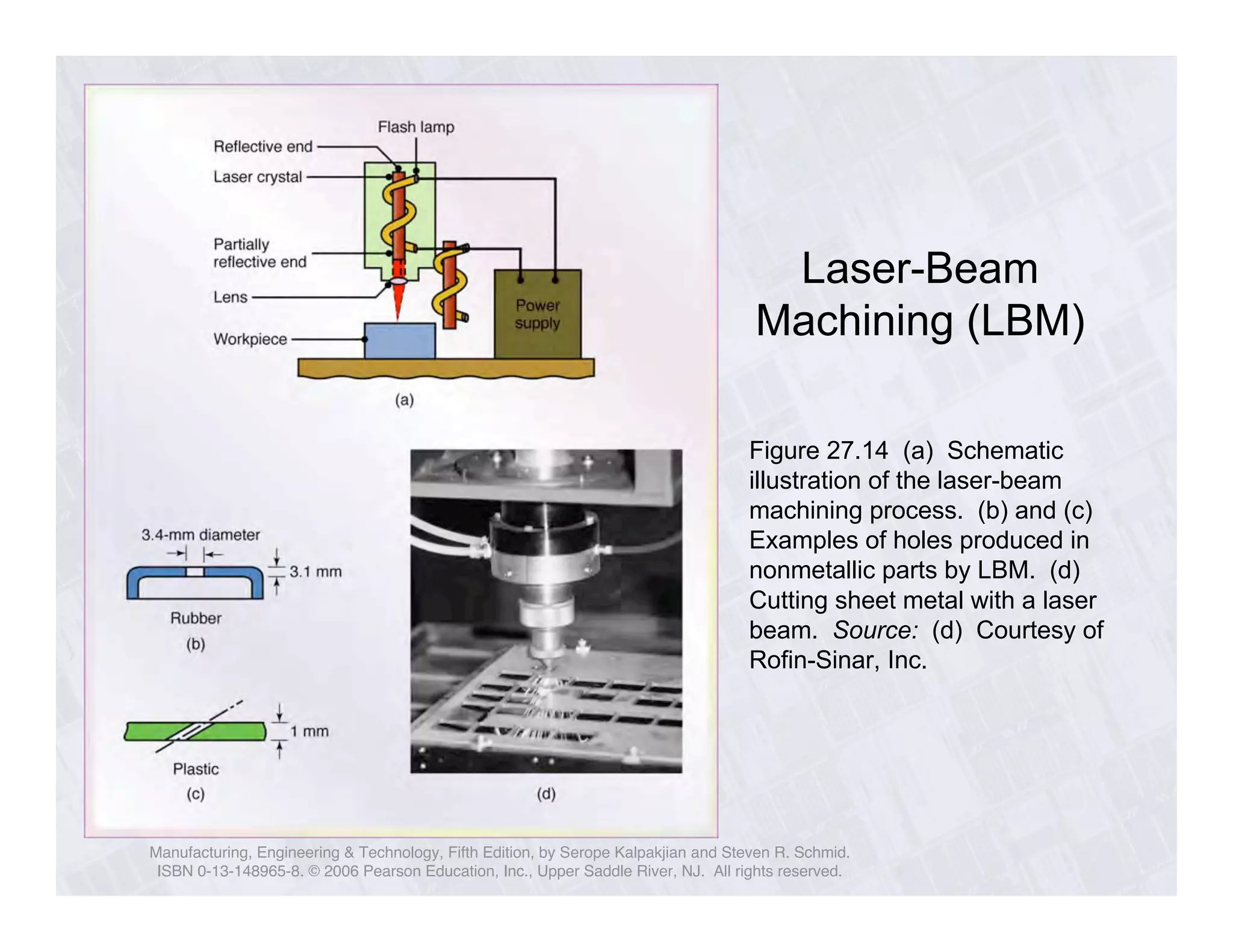
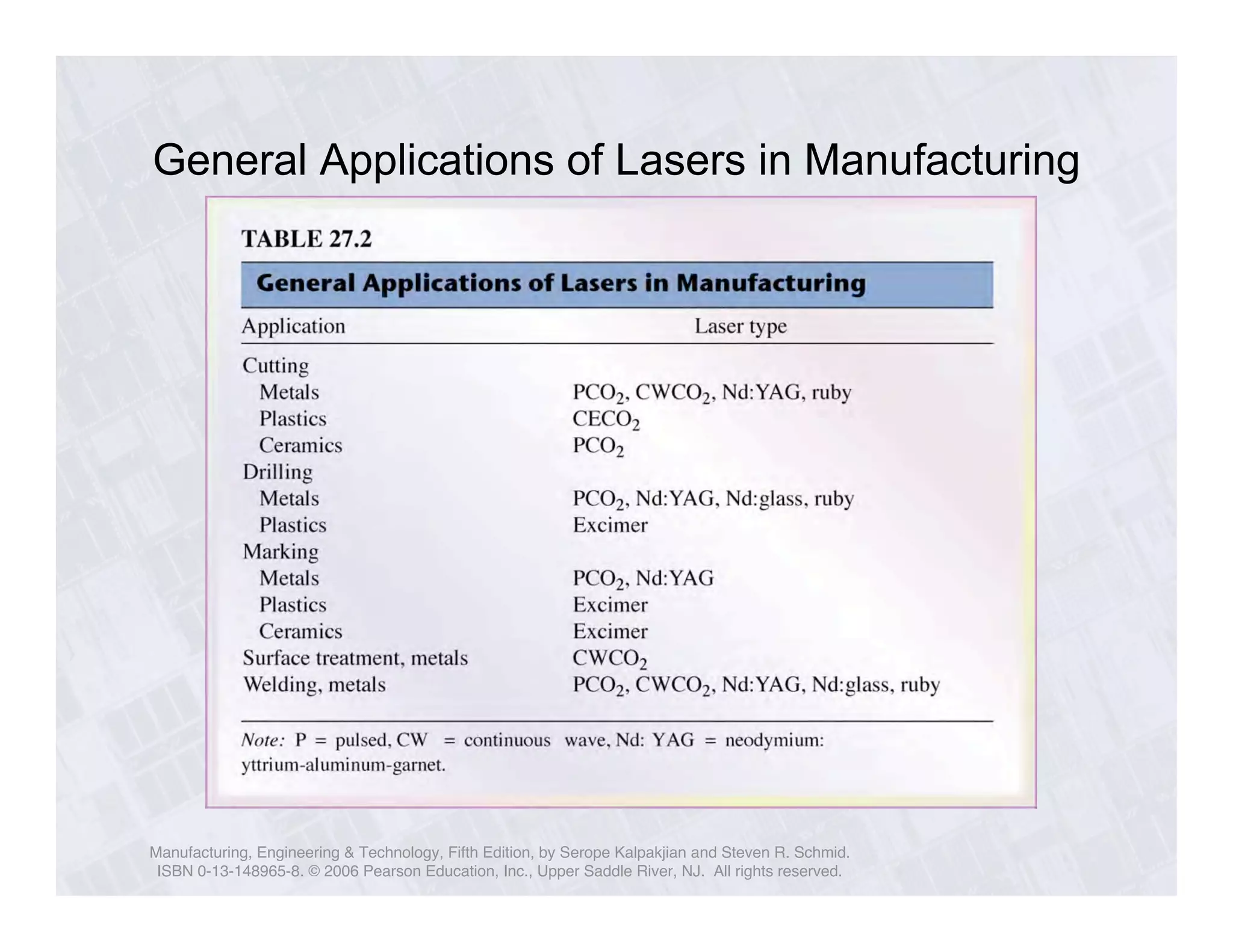
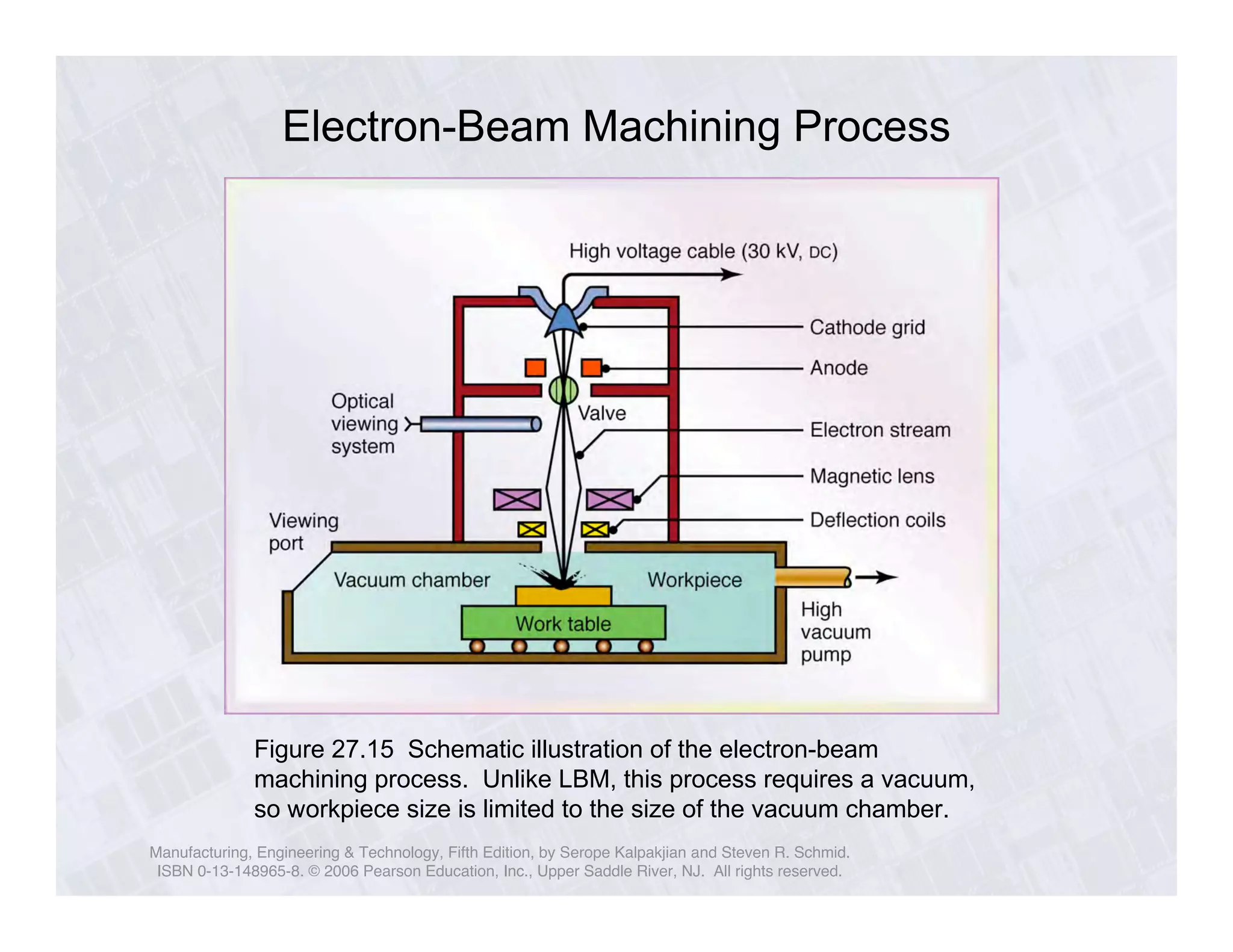
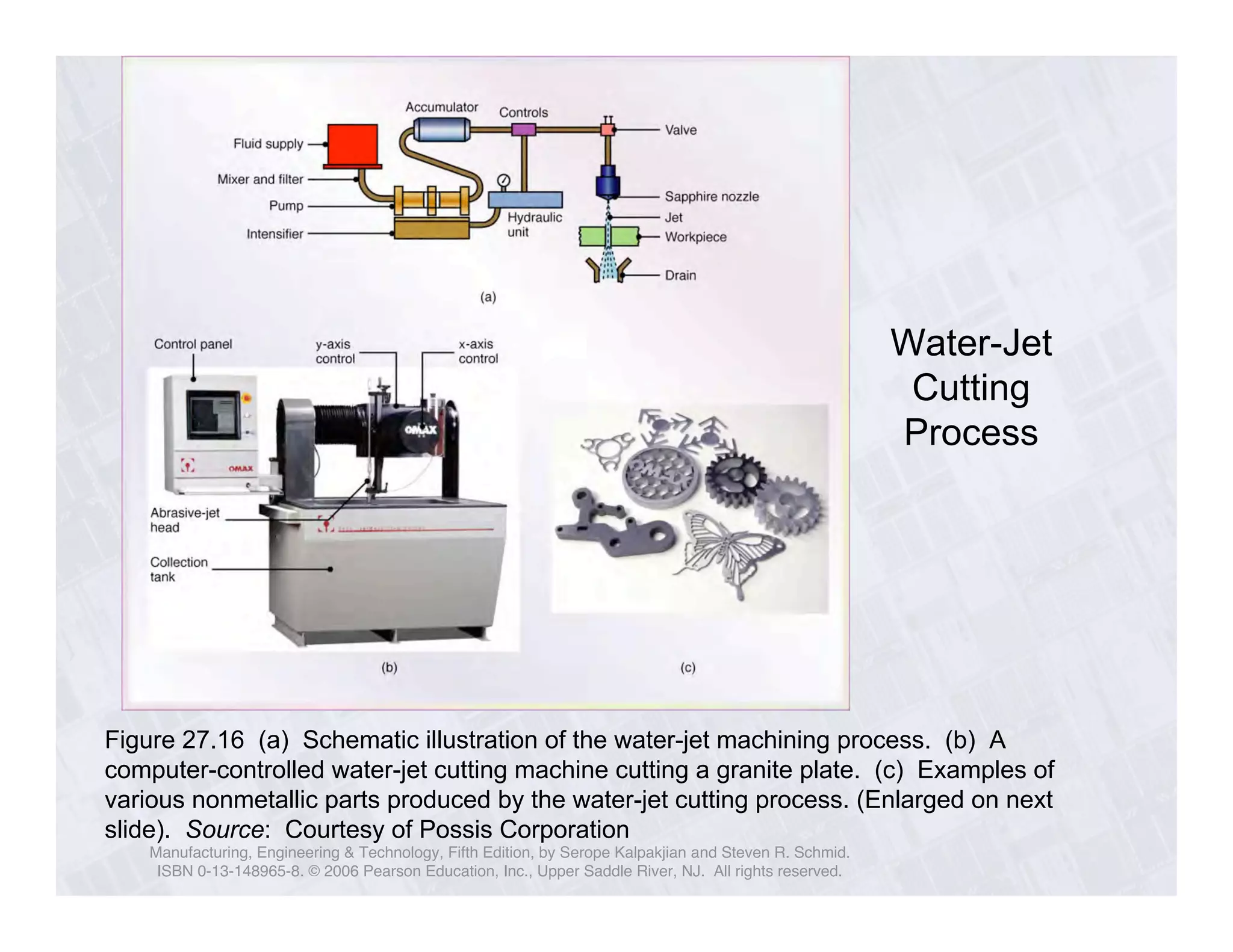
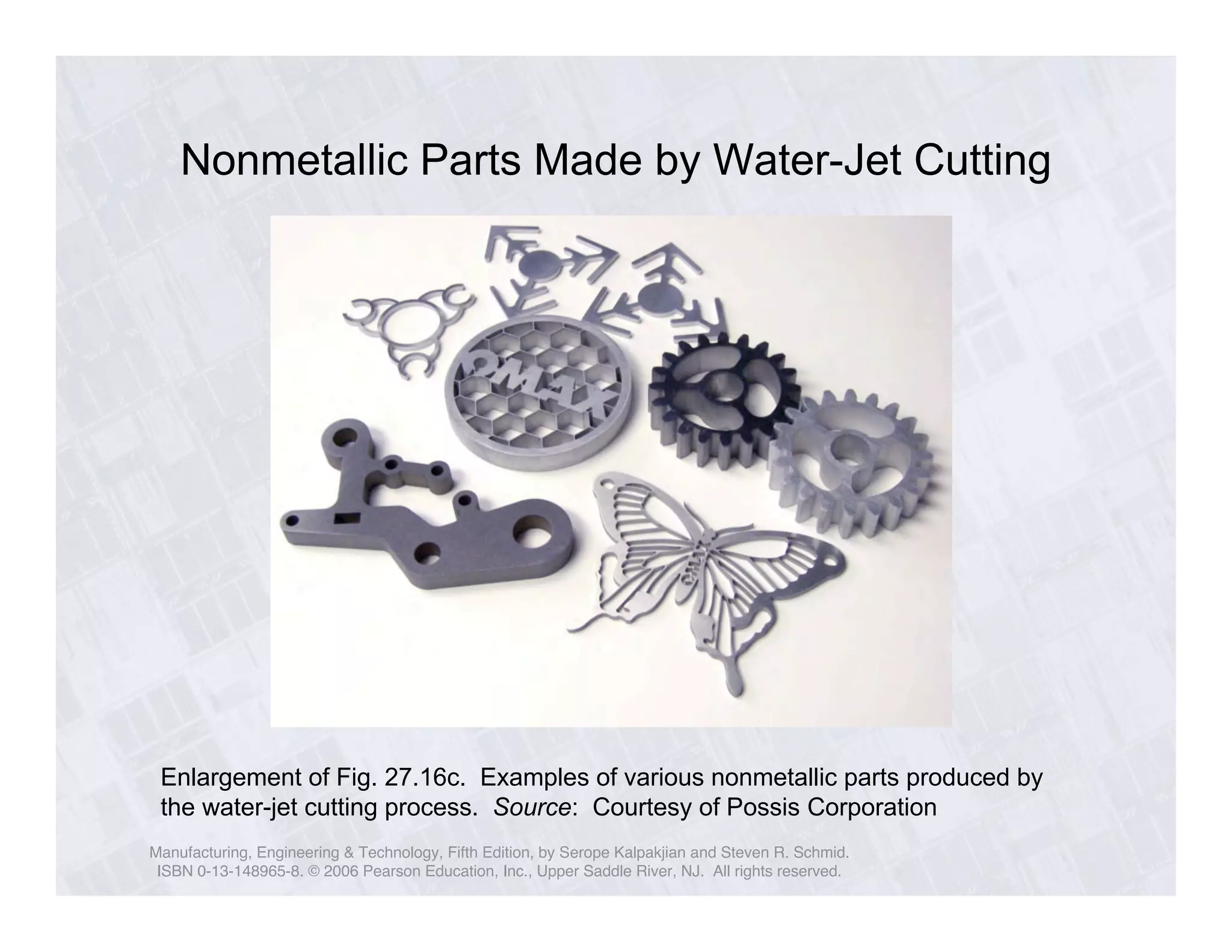
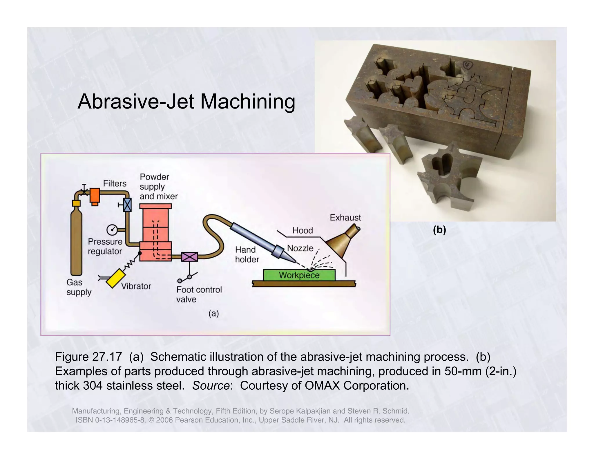
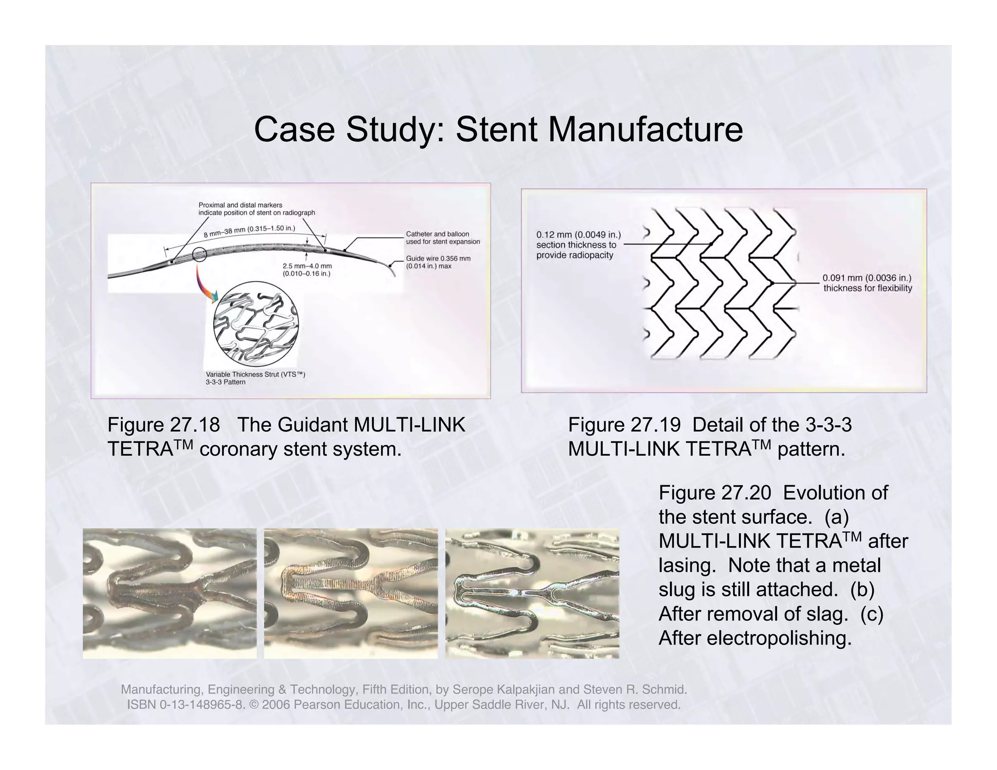

This document discusses advanced machining processes and provides examples of parts produced using these processes. It describes processes such as electrical discharge machining (EDM), chemical milling, laser beam machining, water jet cutting, and abrasive jet machining. Figures show examples of turbine blades, medical implants, and other complex parts that have been produced using these advanced machining techniques which allow shaping hard and delicate materials that cannot be formed through conventional machining.